MPAII Installation and Operations Manual Page 3
Technical orSetup Assistance
Telephone:800.945.7730 (USA) or 801.975.7200 (worldwide) •WorldwideWeb @ http://www.gentner.com
The MPAII contains many unique features that make the MPAII simple to
set up and use. Specific user programming capabilities tailor-make MPAII
functionality to suit the environment in which it is used.
Houses of Worship
This application presents some unique challenges in providing sufficient and
balanced audio for the congregation. Choirs, the soloist, organist or pianist,
speakers, and the minister may all require microphone coverage at one time
or another during the session. The MPAII, with its standard and custom
programming options, allow for such variety.
Talk Shows
The same techniques can be applied in talk show formats where single or
multiple microphones are used. Because of the variety of setup routines for
different talk-show formats, microphones can be preset to automatically gate
on during use and gate off when not in use. Feedback and extra noise are
eliminated.
For more detailed explanations of MPAII use in these applications, see Appendix
D (Page 36).
MPAII
Microphone mixers can be classified into three basic types: non-gating,
gating, and automatic. The MPAII is an automatic microphone mixer, the
most advanced type of mixer. For explanations of non-gating and gating
types, see Appendix A (Page 28).
The MPAII is especially well suited to overcoming excessive room noise,
reverberation, and other problems associated with multi-microphone
installations. The gain (mixing level) of each microphone is automatically
adjusted based on audio levels. The MPAII monitors the audio levels at each
microphone and reduces the mixing level for microphones not in use. By
lowering the level of the microphones not in use, ambient room noise,
reverberation level and total system gain are reduced. This improves the
audio quality for the listener and decreases the possibility of feedback.
The MPAII operates on two basic principles. First, the MPAII gates
microphones on/off when the sound within a microphone’s acceptance
pattern reaches a certain level. Second, the MPAII makes decisions for each
microphone individually, based on each microphone’s specific conditions.
Each microphone operates using the same set of global parameters, as
programmed by the user. However, each microphone behaves independently
according to its own surroundings. Each microphone observes its own
ambient surroundings and makes decisions based on the individual
environment. Thus, a microphone located in a highly reverberant area of the
conference room is able to compensate for the changes in its own
environment.
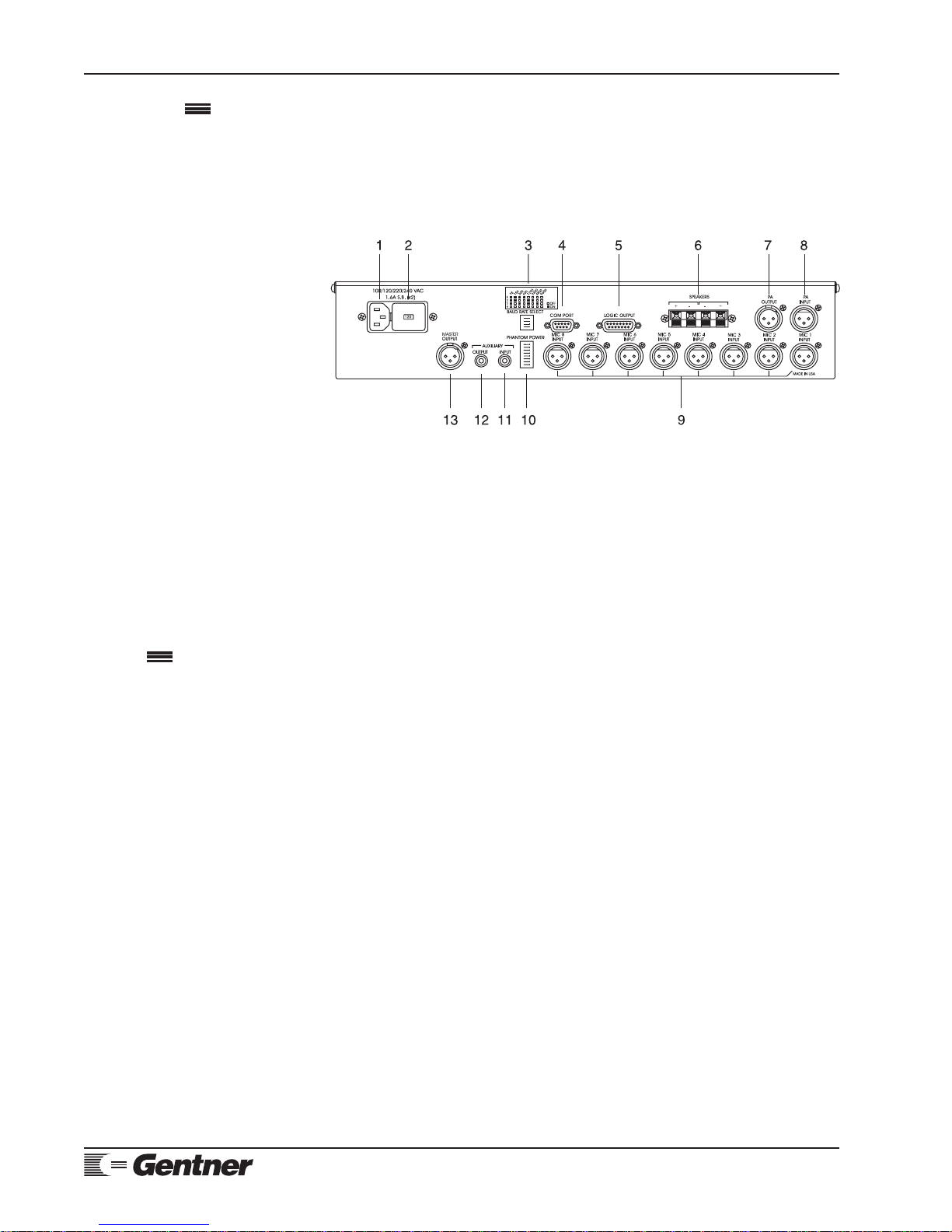
Product
Description