TECHNICAL SUPPORT: 1.800.283.5936 (USA) OR 1.801.974.3760
INSTALLATION AND OPERATION • REAR PANEL
8
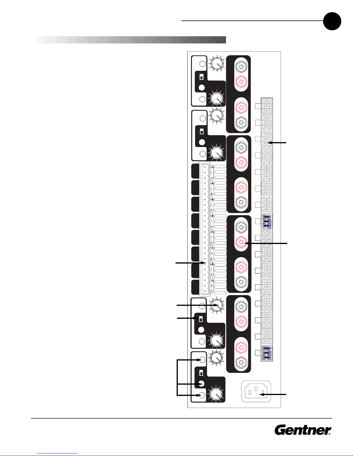
The rear panel controls and connectors of the PA870 amplifier are
described below. Refer to Figure 2 (page 7) for the location of each
feature.
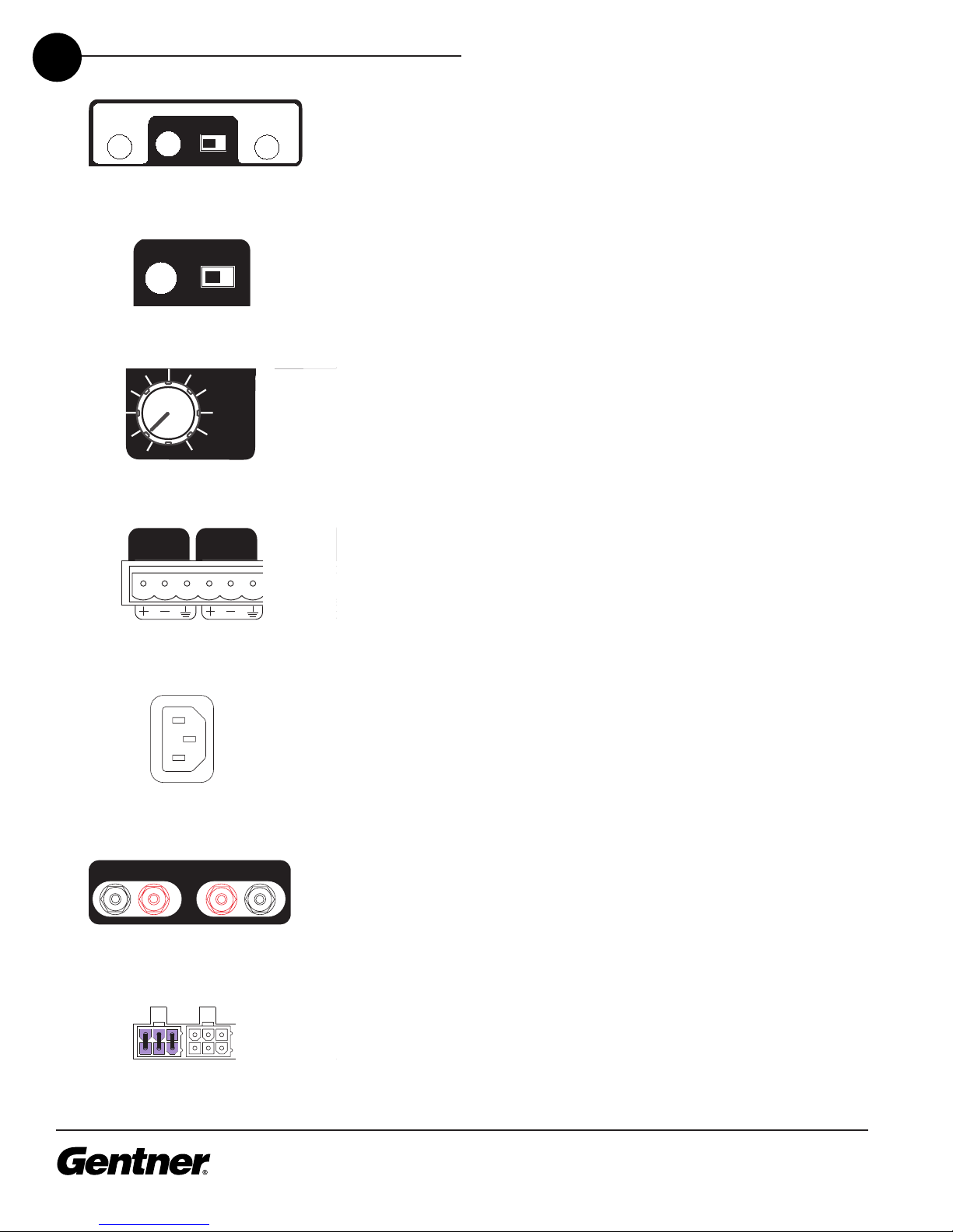
1. LED Indicators. These LEDs indicate signal presence/clipping and
bridge status, and correspond to the LEDs on the front panel.
2. Bridge Switch. There is one bridge switch for each channel pair 1-2,
3-4, 5-6, and 7-8. Channels cannot be bridged outside of these channel
pairs. Move the bridge switch to the right to enable bridging on a
channel pair after you make the appropriate bridge connections. Note
that the shaded areas on the back panel correlate to bridge operation.
3. Volume Control. Rotate the volume control for each channel
clockwise to increase the volume. When bri ging channels, use the
volume control in the sha e area to control the output level of
both channels. The other volume control does not operate in bridged
mode.
4. Phoenix Line-Level Input Receptacles. This bank of receptacles
handles all inputs to the amplifier. The amplifier does not accommodate
mic-level inputs. When making connections, be sure to match polarity.
5. AC Power Receptacle. Connect the power cord (included with the
amplifier) to this receptacle.
6. Output Binding Posts. The output binding posts accept bare wire or
banana plugs. Connect the speakers to these posts.
7. Molex Plug Receptacles. A Molex plug (eight are included with your
PA870) must be plugged into either the 70V or 8Ω Molex plug
receptacle of each channel. Insert a Molex plug into the 70V receptacle
to configure a channel for 70V operation. se the 8Ω receptacle to
configure a channel for 8Ω operation. You can set up any combination
of 70V and 8Ω channels.
Note:
The PA870 will not operate on a given channel without a Molex
plug installe .
Channels configure for 70V output cannot be bri ge .