© R&D Center “GeoStar navigation” Ltd. 2012-12-25 2
Table of Contents
1. Abbreviations ..............................................................................................................................................................................4
2. Technical Description ................................................................................................................................................................. 5
2.1. Introduction .........................................................................................................................................................................5
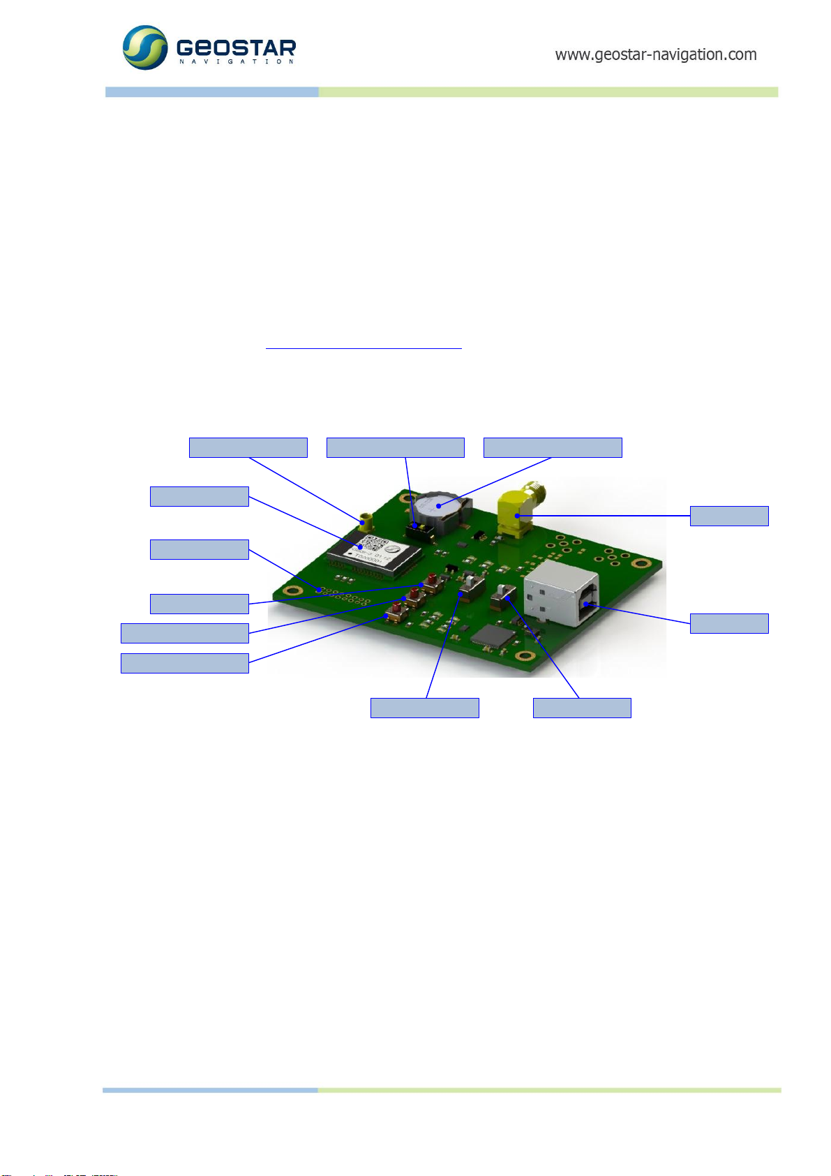
2.2. Overall View .........................................................................................................................................................................5
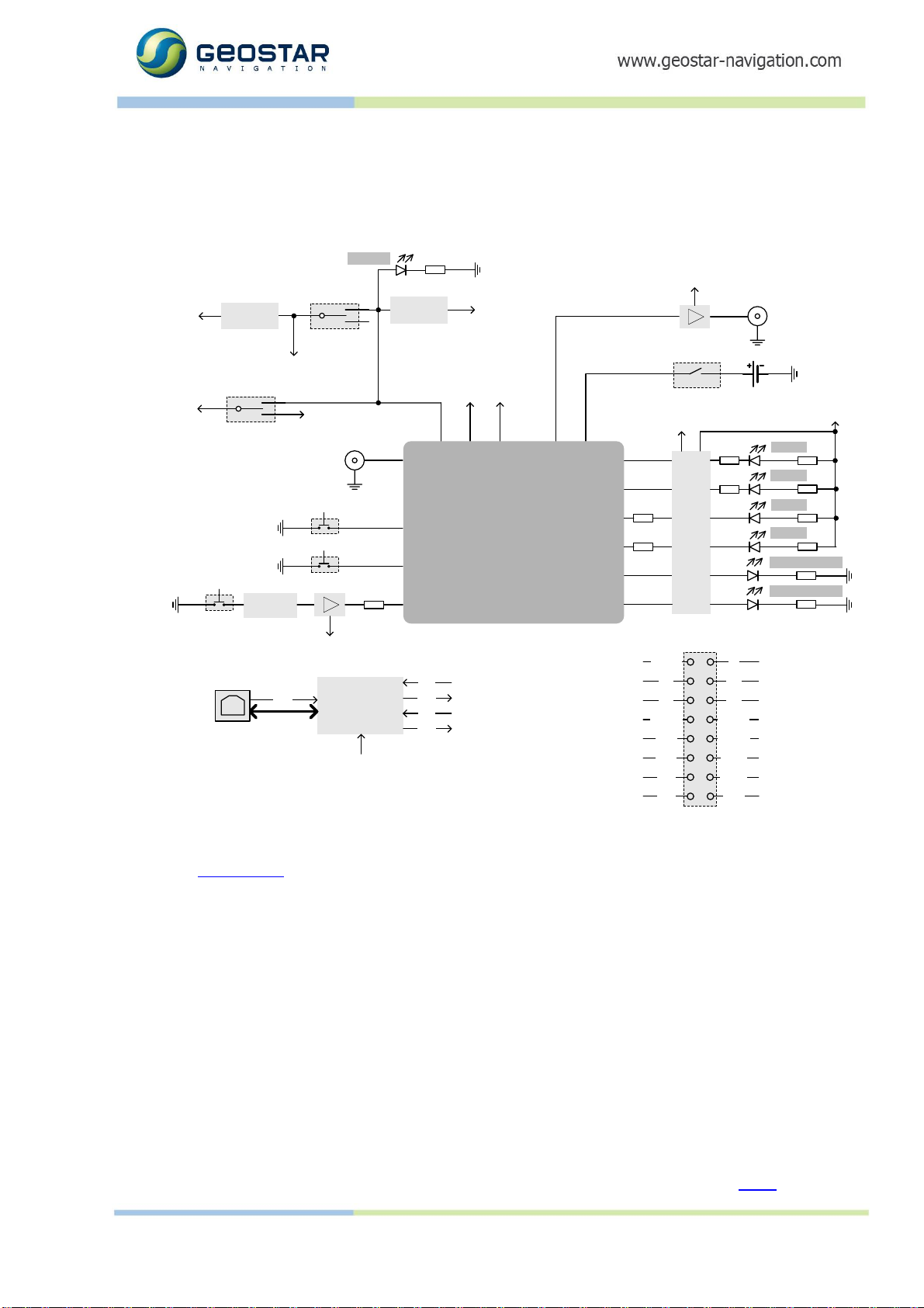
2.3. Block Diagram .....................................................................................................................................................................5
2.3.1 GeoS-3 Connections............................................................................................................................................ 6
2.3.2 Power Plan...........................................................................................................................................................7
2.3.3 Serial Ports...........................................................................................................................................................7
2.3.4 Connectors...........................................................................................................................................................7
2.3.5 Switches, pushbuttons .........................................................................................................................................7
2.3.6 LEDs ....................................................................................................................................................................8
2.3.7 Signal Pads ..........................................................................................................................................................8
2.4. Assembly Drawing ..............................................................................................................................................................9
3. How to Use the Board.................................................................................................................................................................9
3.1. USB Driver ...........................................................................................................................................................................9
3.2. External Connections ....................................................................................................................................................... 10
3.3. Direct Access to GeoS-3 IO Pads .................................................................................................................................... 10
3.4. Getting Started. Operation in Full-power Mode.............................................................................................................. 11
3.5. Operation in Power-saving Mode ....................................................................................................................................12
4. Appendix A. Schematic Diagram ............................................................................................................................................. 13
List of Figures
Figure 1: General View ...................................................................................................................................................................5
Figure 2: Block Diagram.................................................................................................................................................................6
Figure 3: Assembly Drawing ..........................................................................................................................................................9
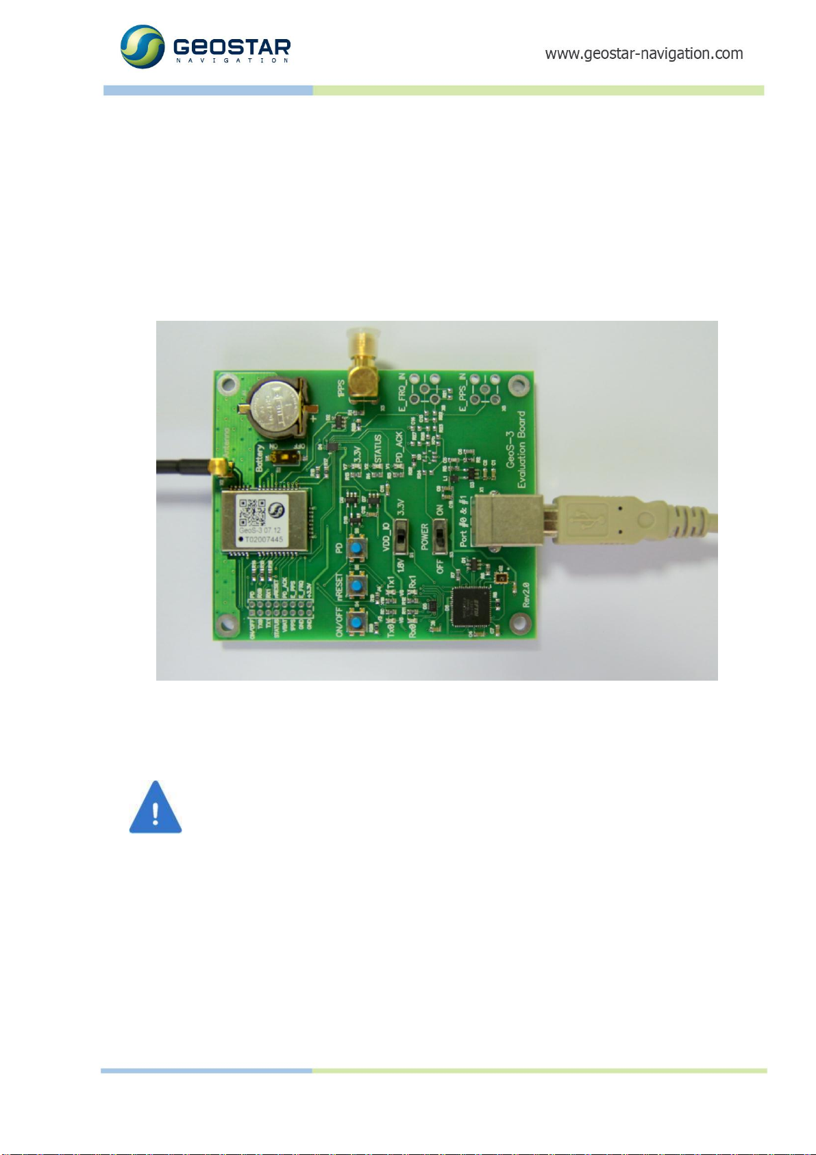
Figure 4: Antenna and USB Connections ...................................................................................................................................10
Figure 5: Schematic Diagram.......................................................................................................................................................13