Gerreka BUL BL33 Operating instructions

1
BUL
Guía rápida de instalación y programación MSB-017/01
AVISO
Esta guía rápida es un resumen del manual de instalación completo. Dicho manual contiene advertencias de
seguridad y otras explicaciones que deben ser tenidas en cuenta. Puede descargar el manual de instalación en
el apartado “Descargas” de la web de Erreka:
http://www.erreka.com/Automatismos/descargaDocumentos.aspx
E187A
2x1mm
2
2x0,5mm
2
8m
MOTOR
ENCODER
TC
TA
TA
TC
Elementos de la instalación completa
Cableado eléctrico
A: Alimentación general
B: Lámpara destellante
C: Fotocélulas (Tx/ Rx)
D: Pulsador o selector de llave
E: Accionador (motor + encoder)
F: Antena
Es imprescindible instalar el tope
de cierre
TC
.
Los topes de apertura
TA
sólo son
necesarios en instalaciones con
apertura exterior.
Para instalaciones con apertura exterior, está disponible el kit opcional NBULR, que es un soporte de
pared especial que permite múltiples posiciones de montaje, facilitando la instalación del accionador.
800
G187B
3,5
Límites de uso
G187A
800
Se debe utilizar electrocerradura para longitudes de hoja superiores a 2,5m.
Valores orientativos. La forma de la hoja y la presencia de fuerte viento, pueden variar
notablemente los valores del gráfico.
BL33 (corto) BL43 (largo)

2
BL33, apertura hacia el interior (carrera: 310mm)
940
310
M187A
100
110
120
130
140
150
160
170
180
190
200
210
110
120
130
140
150
160
170
180
190
200
210
110
120
130
140
150
160
170
180
190
200
210
100
110
120
130
140
150
160
170
180
190
200
210
Ejemplo: A = 170mm, B = 140mm, C = 90º
BL43, apertura hacia el interior (carrera: 410mm)
M187B
140
150
160
170
180
190
200
210
220
230
240
250
110
120
130
140
150
160
170
180
190
200
210
260
270
280
290
300
100
220
230
240
250
110
120
130
140
150
160
170
180
190
200
210
100
220
230
240
250
140
150
160
170
180
190
200
210
220
230
240
250
260
270
280
290
300
1140
410
Ejemplo: A = 220mm, B = 190mm, C = 90º
BL33, apertura hacia el exterior (carrera: 310mm)
M187C
100
110
120
130
140
150
160
170
180
190
200
110
120
130
140
150
160
170
180
190
200
110
120
130
140
150
160
170
180
190
200
100
110
120
130
140
150
160
170
180
190
200
6
3
0
Ejemplo: A = 130mm, B = 142mm, C = 110º
BL43, apertura hacia el exterior (carrera: 410mm)
M187D
140
150
160
170
180
190
200
210
220
230
240
250
110
120
130
140
150
160
170
180
190
200
210
260
270
280
290
300
100
220
230
240
250
110
120
130
140
150
160
170
180
190
200
210
100
220
230
240
250
140
150
160
170
180
190
200
210
220
230
240
250
260
270
280
290
300
730
Ejemplo: A = 220mm, B = 175mm, C = 100º
Las cotas A y B determinan el ángulo de apertura C.
Cotas y posiciones de montaje

3
D187A
D187B
13
Desbloqueo
•Introduzca la llave (1) y gírela hasta que el bombillo
(2) salga unos milímetros.
•Gire la maneta (3) 180º, hasta que el bombillo
coincida con el símbolo $.
Desbloqueo para accionamiento manual: Bloqueo para accionamiento motorizado:
•Gire la maneta (1) 180º, hasta que el bombillo
coincida con el símbolo %.
•Introduzca el bombillo (2) mediante presión y
cúbralo con la tapa (3).
13
D187A
A
P187A
B
P187E
1 Montar el soporte de pared.
Las cotas A y B se miden desde el centro de la bisagra
hasta el centro del orificio del soporte.
P187B
P187C P187D
Montaje
2 Montar el accionador en el soporte de pared.
3 Colocar el soporte de puerta.
Tenga en cuenta que el accionador debe quedar
horizontal.
4 Montar el accionador en el soporte de puerta, ajustar
la rótula y colocar la tapa protectora.
5 Instalar el tope de apertura.
Para apertura interior: abra la
puerta manualmente e instale el
tope de apertura del accionador
(ver figura).
Para apertura exterior: instale
los topes TA (vea “elementos de
la instalación completa”).

4
P187Z
+24Vdc
CN22
GND
G4 G5
GND
V+
P13
SNG1
P14 P15
SNG2
P16
GND
V+
P17
SNG1
P18 P19
SNG2
P20
ENCODER1 ENCODER2
MOTOR2
MOTOR1
CN13
G6
L mp.
G9 G10
VIVO-D201:
VIVO-D201M:
BATTERY
IN/OUT
CHG
VIVO-D201:
FT
VIVO-D201M:
VIVO-D201:
230Vac, max 2.300W
VIVO-D201M:
125Vac, max 1.250W
F2
ST1
FT1
P1 P2 P3
ST2
FT2
P4 P5 P6
STOP
P7 P8
WARNING
LIGHT
P9
P10
24V
P11
P12
LOCK
G7 G8
Courtesy
Light
NL
POWER
+
P21 P22 P23
F3
F1 LB/ LR
P24 P25
EDGE
-FT
(Test)
AUX
24 Vdc
SW1
V
GND SNG1
G1 G2
GND
G3
A1 Accionador 1
A2 Accionador 2
G1/G4 Cable rojo (motor)
G2/G5 Cable azul (motor)
V+ Cable marrón (alimentación encoder)
GND Malla (masa encoder)
SNG1 Cable verde (señal 1 encoder)
SW1 Interruptor general
•Seleccione el número de accionadores mediante C0 (C001: un accionador, C002: dos accionadores).
•Programe C7 para funcionamiento con encoder (C701).
•Para el accionador BUL, programe C301.
Conexiones eléctricas VIVO-D201(M)
Comprobación del sentido de giro: tras conectar la alimentación eléctrica y activar cualquiera de
los dispositivos de marcha, la puerta realiza un reset (el display indica rS): la puerta se cierra hasta
que hace tope, asignando a dicho tope la posición “puerta cerrada”. Si durante el reset, en lugar de
cerrarse se abre, cambie el sentido de giro (C101 ó C102 para A1 y C201 ó C202 para A2).

5
BUL
Guide rapide d’installation et programmation MSB-017/01
AVERTISSEMENT
Ce guide rapide est un résumé du manuel d’installation complet. Ce manuel contient des
avertissements de sécurité et d’autres explications qui doivent être pris en compte. Vous pouvez
télécharger le manuel d’installation dans la section « Téléchargements » du site web d’Erreka.
http://www.erreka.com/Automatismos/descargaDocumentos.aspx
E187A
2x1mm
2
2x0,5mm
2
8m
MOTOR
ENCODER
TC
TA
TA
TC
Éléments de l’installation complète
Câblage électrique
A: Alimentation générale
B: Feu clignotant
C: Photocellules (Tx / Rx)
D: Bouton-poussoir ou sélecteur à clef
E: Actionneur (moteur + encodeur)
F: Antenne
Il est indispensable d’installer la
butée de fermeture
TC
.
Les butées d’ouverture
TA
ne sont
nécessaires que dans les installations
avec une ouverture extérieure.
Pour les installations avec une ouverture extérieure, le kit optionnel NBULR est disponible. Il s’agit d’un support
de mur spécial qui permet de multiples positions de montage, ce qui facilite l’installation de l’actionneur.
800
G187B
3,5
Limites d´utilisation
G187A
800
Il faut utiliser une électroserrure pour des longueurs de vantail supérieures à 2,5m.
Valeurs approximatives. La forme du vantail et la présence de vent peuvent varier notablement
les valeurs du graphique.
BL33 (court) BL43 (long)

6
BL33, ouverture vers l´intérieur (course : 310mm)
940
310
M187A
100
110
120
130
140
150
160
170
180
190
200
210
110
120
130
140
150
160
170
180
190
200
210
110
120
130
140
150
160
170
180
190
200
210
100
110
120
130
140
150
160
170
180
190
200
210
Exemple : A = 170mm, B = 140mm, C = 90º
BL43, ouverture vers l´intérieur (course : 410mm)
M187B
140
150
160
170
180
190
200
210
220
230
240
250
110
120
130
140
150
160
170
180
190
200
210
260
270
280
290
300
100
220
230
240
250
110
120
130
140
150
160
170
180
190
200
210
100
220
230
240
250
140
150
160
170
180
190
200
210
220
230
240
250
260
270
280
290
300
1140
410
Exemple : A = 220mm, B = 190mm, C = 90º
BL33, ouverture vers l´extérieur (course : 310mm)
M187C
100
110
120
130
140
150
160
170
180
190
200
110
120
130
140
150
160
170
180
190
200
110
120
130
140
150
160
170
180
190
200
100
110
120
130
140
150
160
170
180
190
200
6
3
0
Exemple : A = 130mm, B = 142mm, C = 110º
BL43, ouverture vers l´extérieur (course : 410mm)
M187D
140
150
160
170
180
190
200
210
220
230
240
250
110
120
130
140
150
160
170
180
190
200
210
260
270
280
290
300
100
220
230
240
250
110
120
130
140
150
160
170
180
190
200
210
100
220
230
240
250
140
150
160
170
180
190
200
210
220
230
240
250
260
270
280
290
300
730
Exemple : A = 220mm, B = 175mm, C = 100º
Les cotes A et B déterminent l´angle d´ouverture C.
Cotes et positions de montage

7
D187A
D187B
13
Déblocage
•Introduisez la clé (1) et tournez-la jusqu’à ce que le
cylindre (2) sorte de quelques millimètres.
•Tournez la manette (3) de 180º, jusqu’à ce que le
cylindre coïncide avec le symbole $.
Déblocage pour un actionnement manuel : Blocage pour un actionnement motorisé :
•Tournez la manette (1) de 180º, jusqu’à ce que le
cylindre coïncide avec le symbole %.
•Introduisez le cylindre (2) en exerçant une pression
et couvrez-le avec le couvercle (3).
13
D187A
A
P187A
B
P187E
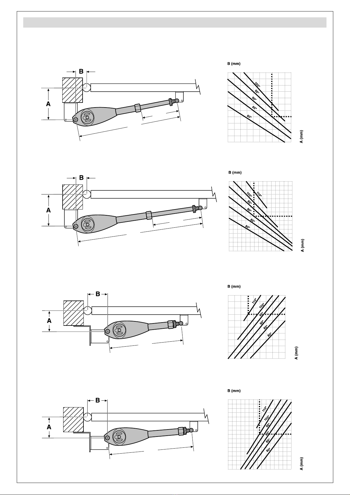
1 Monter le support de mur.
Las cotes A et B se mesurent depuis le centre de la
charnière jusqu’au centre de l’orifice du support.
P187B
P187C P187D
Montage
2 Monter l´actionneur sur le support de mur.
3 Placer le support de porte.
L'actionneur doit rester horizontal.
4 Monter l’actionneur sur le support de porte, régler la
rotule et placer le couvercle protecteur.
5 Installer la butée d’ouverture.
Pour une ouverture intérieure :
ouvrez la porte manuellement et
installez la butée d’ouverture de
l’actionneur (voir figure).
Pour une ouverture extérieure :
installez les butées TA (consultez «
éléments de l’installation complète »).

8
P187Z
+24Vdc
CN22
GND
G4 G5
GND
V+
P13
SNG1
P14 P15
SNG2
P16
GND
V+
P17
SNG1
P18 P19
SNG2
P20
ENCODER1 ENCODER2
MOTOR2
MOTOR1
CN13
G6
L mp.
G9 G10
VIVO-D201:
VIVO-D201M:
BATTERY
IN/OUT
CHG
VIVO-D201:
FT
VIVO-D201M:
VIVO-D201:
230Vac, max 2.300W
VIVO-D201M:
125Vac, max 1.250W
F2
ST1
FT1
P1 P2 P3
ST2
FT2
P4 P5 P6
STOP
P7 P8
WARNING
LIGHT
P9
P10
24V
P11
P12
LOCK
G7 G8
Courtesy
Light
NL
POWER
+
P21 P22 P23
F3
F1 LB/ LR
P24 P25
EDGE
-FT
(Test)
AUX
24 Vdc
SW1
V
GND SNG1
G1 G2
GND
G3
A1 Actionneur 1
A2 Actionneur 2
G1/G4 Câble rouge (moteur)
G2/G5 Câble bleu (moteur)
V+ Câble marron (alimentation encodeur)
GND Maille (masse encodeur)
SNG1 Câble vert (signal 1 encodeur)
SW1 Interrupteur général
•Sélectionnez le nombre d’actionneurs avec C0 (C001 : un actionneur, C002 : deux actionneurs).
•Programmez C7 pour un fonctionnement avec encodeur (C701).
•Pour l’actionneur BUL, programmez C301.
Connexions électriques VIVO-D201(M)
Vérification du sens de rotation : après avoir connecté l’alimentation électrique et avoir activé l’un
des dispositifs de marche, la porte réalise un reset (le display indique rS) : la porte se ferme jusqu’a
atteindre la butée, en assignant à cette butée la position de « porte fermée ». Si pendant le reset,
elle s'ouvre au lieu de se fermer, changez les sens de rotation (C101 ou C102 pour A1 et C201 ou
C202 pour A2).

9
BUL
Quick installation and programming guide MSB-017/01
IMPORTANT
NOTE
This quick guide is a summary of the complete installation manual. The manual contains safety warnings
and other explanations which must be taken into account. The installation manual can be downloaded
by going to the "Downloads" section of Erreka website:
http://www.erreka.com/Automatismos/descargaDocumentos.aspx
E187A
2x1mm
2
2x0,5mm
2
8m
MOTOR
ENCODER
TC
TA
TA
TC
Elements of the complete installation
Electrical cabling
A: Main power supply
B: Flashing light
C: Photocells (Tx/Rx)
D: Pushbutton or key switch
E: Operator (motor + encoder)
F: Antenna
The
TC
closing stopper must be
installed.
The
TA
opening stoppers are only
necessary in outward opening
facilities.
The optional NBULR kit is available for outward opening facilities; this is a special wall bracket which
allows multiple mounting positions, thus making it easier to install the operator.
800
G187B
3,5
Limits on use
G187A
800
We recommend using an electrolock for leaf lengths of over 2.5m.
Values for orientation purposes only. The shape of the leaf and the presence of strong wind may
bring notable differences in the values of the chart.
BL33 (short) BL43 (long)

10
BL33, inward opening (travel: 310mm)
940
310
M187A
100
110
120
130
140
150
160
170
180
190
200
210
110
120
130
140
150
160
170
180
190
200
210
110
120
130
140
150
160
170
180
190
200
210
100
110
120
130
140
150
160
170
180
190
200
210
Example: A = 170mm, B = 140mm, C = 90º
BL43, inward opening (travel: 410mm)
M187B
140
150
160
170
180
190
200
210
220
230
240
250
110
120
130
140
150
160
170
180
190
200
210
260
270
280
290
300
100
220
230
240
250
110
120
130
140
150
160
170
180
190
200
210
100
220
230
240
250
140
150
160
170
180
190
200
210
220
230
240
250
260
270
280
290
300
1140
410
Example: A = 220mm, B = 190mm, C = 90º
BL33, outward opening (travel: 310mm)
M187C
100
110
120
130
140
150
160
170
180
190
200
110
120
130
140
150
160
170
180
190
200
110
120
130
140
150
160
170
180
190
200
100
110
120
130
140
150
160
170
180
190
200
6
3
0
Example: A = 130mm, B = 142mm, C = 110º
BL43, outward opening (travel: 410mm)
M187D
140
150
160
170
180
190
200
210
220
230
240
250
110
120
130
140
150
160
170
180
190
200
210
260
270
280
290
300
100
220
230
240
250
110
120
130
140
150
160
170
180
190
200
210
100
220
230
240
250
140
150
160
170
180
190
200
210
220
230
240
250
260
270
280
290
300
730
Example: A = 220mm, B = 175mm, C = 100º
Levels A and B determine the opening angle C.
Assembly positions and levels

11
D187A
D187B
13
Unlocking
•Insert the key (1) and turn until the cylinder (2)
protrudes a few millimetres.
•Turn the handle (3) 180º, until the cylinder coincides
with the $symbol.
Unlocking for manual operation: Motorised operation locking:
•Turn the handle (1) 180º, until the cylinder coincides
with the %symbol.
•Insert the cylinder (2) by pushing and cover it (3).
13
D187A
A
P187A
B
P187E
1 Mount the wall support.
Levels A and B are measured from the centre of the
hinge to the centre of the bracket orifice.
P187B
P187C P187D
Assembly
2 Mount the operator on the wall support.
3 Position the gate support.
Bear in mind that the operator must be horizontal.
4 Mount the operator on the gate support, adjust the
swivel joint and position the protective cover.
5 Install the opening stopper.
For inward opening: open the
gate manually and install the
operator opening stopper (see
figure).
For outward opening: install
the TA stoppers (see "elements
of the complete installation").

12
P187Z
+24Vdc
CN22
GND
G4 G5
GND
V+
P13
SNG1
P14 P15
SNG2
P16
GND
V+
P17
SNG1
P18 P19
SNG2
P20
ENCODER1 ENCODER2
MOTOR2
MOTOR1
CN13
G6
L mp.
G9 G10
VIVO-D201:
VIVO-D201M:
BATTERY
IN/OUT
CHG
VIVO-D201:
FT
VIVO-D201M:
VIVO-D201:
230Vac, max 2.300W
VIVO-D201M:
125Vac, max 1.250W
F2
ST1
FT1
P1 P2 P3
ST2
FT2
P4 P5 P6
STOP
P7 P8
WARNING
LIGHT
P9
P10
24V
P11
P12
LOCK
G7 G8
Courtesy
Light
NL
POWER
+
P21 P22 P23
F3
F1 LB/ LR
P24 P25
EDGE
-FT
(Test)
AUX
24 Vdc
SW1
V
GND SNG1
G1 G2
GND
G3
A1 Operator 1
A2 Operator 2
G1/G4 Red cable (motor)
G2/G5 Blue cable (motor)
V+ Brown cable (encoder supply)
GND Mesh (encoder mass)
SNG1 Green cable (encoder signal 1)
SW1 Main switch
•Select the number of operators using C0 (C001: one operator, C002: two operators).
•Programme C7 for operation with encoder (C701).
•For the BUL operator, programme C301.
Electrical connections VIVO-D201(M)
Turning direction check: after connecting the power and activating any of the key devices, the
gate makes a reset (the display showsrS): the gate closes until it reaches the stopper, assigning this
stopper with the position "gate closed" If it opens instead of closes during reset, change the turning
direction (C101 or C102 for A1 and C201 or C202 for A2).

13
BUL
Guia rápido de instalação e programação MSB-017/01
AVISO
Este guia rápido é um resumo do manual de instalação completo. Este manual contém advertências de
segurança e outras explicações a ter em atenção. Pode efectuar o download do manual de instalação na
secção “Downloads” do site da Erreka:
http://www.erreka.com/Automatismos/descargaDocumentos.aspx
E187A
2x1mm
2
2x0,5mm
2
8m
MOTOR
ENCODER
TC
TA
TA
TC
Elementos da instalação completa
Cablagem eléctrica
A: Alimentação geral
B: Lâmpada de sinalização
C: Fotocélulas (Tx/ Rx)
D: Botão ou selector de chave
E: Accionador (motor + encoder)
F: Antena
É imprescindível instalar o
batente de fecho
TC
.
Os batentes de abertura
TA
só são
necessários nas instalações com
abertura exterior.
Para as instalações com abertura exterior está disponível o kit opcional NBULR, que é um suporte de
parede especial que possibilita múltiplas posições de montagem, facilitando a instalação do accionador.
800
G187B
3,5
Limites de uso
G187A
800
Deve utilizar electrofechadura para comprimentos de folha superiores a 2,5 m.
Valores orientativos. A forma da folha e a presença de vento forte podem alterar os valores do
gráfico de forma significativa.
BL33 (curto) BL43 (comprido)

14
BL33, abertura para o interior (curso: 310 mm)
940
310
M187A
100
110
120
130
140
150
160
170
180
190
200
210
110
120
130
140
150
160
170
180
190
200
210
110
120
130
140
150
160
170
180
190
200
210
100
110
120
130
140
150
160
170
180
190
200
210
Exemplo: A = 170 mm, B = 140 mm, C = 90º
BL43, abertura para o interior (curso: 410 mm)
M187B
140
150
160
170
180
190
200
210
220
230
240
250
110
120
130
140
150
160
170
180
190
200
210
260
270
280
290
300
100
220
230
240
250
110
120
130
140
150
160
170
180
190
200
210
100
220
230
240
250
140
150
160
170
180
190
200
210
220
230
240
250
260
270
280
290
300
1140
410
Exemplo: A = 220 mm, B = 190 mm, C = 90º
BL33, abertura para o exterior (curso: 310 mm)
M187C
100
110
120
130
140
150
160
170
180
190
200
110
120
130
140
150
160
170
180
190
200
110
120
130
140
150
160
170
180
190
200
100
110
120
130
140
150
160
170
180
190
200
6
3
0
Exemplo: A = 130 mm, B = 142 mm, C = 110º
BL43, abertura para o exterior (curso: 410 mm)
M187D
140
150
160
170
180
190
200
210
220
230
240
250
110
120
130
140
150
160
170
180
190
200
210
260
270
280
290
300
100
220
230
240
250
110
120
130
140
150
160
170
180
190
200
210
100
220
230
240
250
140
150
160
170
180
190
200
210
220
230
240
250
260
270
280
290
300
730
Exemplo: A = 220 mm, B = 175 mm, C = 100º
As cotas A e B determinam o ângulo de abertura C.
Cotas e posições de montagem

15
D187A
D187B
13
Desbloqueio
•Introduza a chave (1) e gire-a até que o cilindro da
fechadura (2) saia alguns milímetros.
•Gire a maçaneta (3) em 180º, até que o cilindro da
fechadura coincida com o símbolo $.
Desbloqueio para accionamento manual: Bloqueio para accionamento motorizado:
•Gire a maçaneta (1) em 180º, até que o cilindro da
fechadura coincida com o símbolo %.
•Introduza o cilindro da fechadura (2) com pressão e
cubra-o com a tampa (3).
13
D187A
A
P187A
B
P187E
1 Montar o suporte de parede.
As cotas A e B são medidas desde o centro da
dobradiça até ao centro do orifício do suporte.
P187B
P187C P187D
Montagem
2 Montar o accionador no suporte de parede.
3 Colocar o suporte de porta.
Ter em atenção que o accionador deve ficar na
horizontal.
4 Montar o accionador no suporte de porta, ajustar a
rótula e colocar a tampa protectora.
5 Instalar o batente de abertura.
Para a abertura interior: abra a
porta manualmente e instale o
batente de abertura do
accionador (ver figura).
Para a abertura exterior: instale
os batentes TA (ver “elementos da
instalação completa”).

16
P187Z
+24Vdc
CN22
GND
G4 G5
GND
V+
P13
SNG1
P14 P15
SNG2
P16
GND
V+
P17
SNG1
P18 P19
SNG2
P20
ENCODER1 ENCODER2
MOTOR2
MOTOR1
CN13
G6
L mp.
G9 G10
VIVO-D201:
VIVO-D201M:
BATTERY
IN/OUT
CHG
VIVO-D201:
FT
VIVO-D201M:
VIVO-D201:
230Vac, max 2.300W
VIVO-D201M:
125Vac, max 1.250W
F2
ST1
FT1
P1 P2 P3
ST2
FT2
P4 P5 P6
STOP
P7 P8
WARNING
LIGHT
P9
P10
24V
P11
P12
LOCK
G7 G8
Courtesy
Light
NL
POWER
+
P21 P22 P23
F3
F1 LB/ LR
P24 P25
EDGE
-FT
(Test)
AUX
24 Vdc
SW1
V
GND SNG1
G1 G2
GND
G3
A1 Accionador 1
A2 Accionador 2
G1/G4 Cabo vermelho (motor)
G2/G5 Cabo azul (motor)
V+ Cabo castanho (alimentação encoder)
GND Malha (massa encoder)
SNG1 Cabo verde (sinal 1 encoder)
SW1 Interruptor geral
•Seleccione o número de accionadores através de C0 (C001: um accionador, C002: dois accionadores).
•Programe C7 para o funcionamento com encoder (C701).
•Para o accionador BUL programe C301.
Ligações eléctricas VIVO-D201(M)
Verificação do sentido de rotação: depois de ligar a alimentação eléctrica e activar qualquer um
dos dispositivos de funcionamento, a porta realiza um reset (o ecrã indica rS): a porta fecha-se até
chegar ao batente, atribuindo a esse batente a posição “porta fechada”. Se durante o reset a porta
se abrir (em vez de se fechar), altere o sentido de rotação (C101 ou C102 para A1 e C201 ou C202
para A2).

17
BUL
Kurzführer Installation und Programmierung MSB-017/01
HINWEIS
Dieser Kurzführer ist eine Zusammenfassung der kompletten Montageanleitung. Diese enthält
Sicherheitshinweise und andere Erläuterungen, die beachtet werden müssen. Die Montageanleitung können
Sie auf der Erreka-Website unter „Downloads“ herunterladen:
http://www.erreka.com/Automatismos/descargaDocumentos.aspx
E187A
2x1mm
2
2x0,5mm
2
8m
MOTOR
ENCODER
TC
TA
TA
TC
Elemente der kompletten Anlage
Stromkabel
A: Hauptstromversorgung
B: Blinklampe
C: Lichtschranke (Tx/Rx)
D: Drucktaster oder Schlüsseltaster
E: Antrieb (Motor + Encoder)
F: Antenne
Der Schließanschlag
TC
muss
unbedingt installiert werden.
Die Öffnungsanschläge
TA
sind nur
bei Anlagen mit Öffnung nach
Außen erforderlich.
Für Anlagen mit Öffnung nach Außen gibt es das optionale Set NBULR, eine spezielle Wandhalterung,
die zahlreiche Montagemöglichkeiten erlaubt, was die Montage des Antriebs erleichtert.
800
G187B
3,5
Gebrauchsgrenzen
G187A
800
Das verwendete Elektroschloss muss für Torflügellängen über 2,5m geeignet sein.
Richtwerte. Die Form des Torflügels und starker Wind können die Werte der Grafik
deutlich verändern.
BL33 (kurz) BL43 (lang)

18
BL33, Öffnung nach Innen (Hub: 310mm)
940
310
M187A
100
110
120
130
140
150
160
170
180
190
200
210
110
120
130
140
150
160
170
180
190
200
210
110
120
130
140
150
160
170
180
190
200
210
100
110
120
130
140
150
160
170
180
190
200
210
Beispiel: A = 170mm, B = 140mm, C = 90º
BL43, Öffnung nach Innen (Hub: 410mm)
M187B
140
150
160
170
180
190
200
210
220
230
240
250
110
120
130
140
150
160
170
180
190
200
210
260
270
280
290
300
100
220
230
240
250
110
120
130
140
150
160
170
180
190
200
210
100
220
230
240
250
140
150
160
170
180
190
200
210
220
230
240
250
260
270
280
290
300
1140
410
Beispiel: A = 220mm, B = 190mm, C = 90º
BL33, Öffnung nach Außen (Hub: 310mm)
M187C
100
110
120
130
140
150
160
170
180
190
200
110
120
130
140
150
160
170
180
190
200
110
120
130
140
150
160
170
180
190
200
100
110
120
130
140
150
160
170
180
190
200
6
3
0
Beispiel: A = 130mm, B = 142mm, C = 110º
BL43, Öffnung nach Außen (Hub: 410mm)
M187D
140
150
160
170
180
190
200
210
220
230
240
250
110
120
130
140
150
160
170
180
190
200
210
260
270
280
290
300
100
220
230
240
250
110
120
130
140
150
160
170
180
190
200
210
100
220
230
240
250
140
150
160
170
180
190
200
210
220
230
240
250
260
270
280
290
300
730
Beispiel: A = 220mm, B = 175mm, C = 100º
Die Maße A und B bestimmen den Öffnungswinkel C.
Montagemaße und -positionen

19
D187A
D187B
13
Entriegelung
•Stecken Sie den Schlüssel (1) ein und drehen Sie ihn,
bis der Zylinder (2) ein paar Millimeter herauskommt.
•Drehen Sie den Hebel (3) um 180º, bis der Zylinder
mit dem Symbol $übereinstimmt.
Entriegelung für manuelle Betätigung: Verriegelung für motorischen Antrieb:
•Drehen Sie den Hebel (1) um 180º, bis der Zylinder
mit dem Symbol %übereinstimmt.
•Drücken Sie den Zylinder (2) hinein und decken Sie
ihn mit dem Deckel (3) ab.
13
D187A
A
P187A
B
P187E
1 Wandhalterung montieren
Die Maße A und B werden vom Mittelpunkt des
Scharniers bis zum Mittelpunkt der
Halterungsöffnung gemessen.
P187B
P187C P187D
Montage
2 Antrieb an der Wandhalterung montieren.
3 Torhalterung anbringen.
Beachten Sie, dass der Antrieb waagerecht liegen
muss.
4 Den Antrieb an der Torhalterung montieren, das
Gelenk einstellen und die Schutzabdeckung
anbringen.
5 Den Öffnungsanschlag montieren.
Für Öffnung nach Innen: Öffnen Sie
das Tor manuell und installieren Sie
den Öffnungsanschlag des Antriebs
(siehe Abbildung).
Für Öffnung nach Außen:
Installieren Sie die Anschläge TA (siehe
„Elemente der kompletten Anlage“).

20
P187Z
+24Vdc
CN22
GND
G4 G5
GND
V+
P13
SNG1
P14 P15
SNG2
P16
GND
V+
P17
SNG1
P18 P19
SNG2
P20
ENCODER1 ENCODER2
MOTOR2
MOTOR1
CN13
G6
L mp.
G9 G10
VIVO-D201:
VIVO-D201M:
BATTERY
IN/OUT
CHG
VIVO-D201:
FT
VIVO-D201M:
VIVO-D201:
230Vac, max 2.300W
VIVO-D201M:
125Vac, max 1.250W
F2
ST1
FT1
P1 P2 P3
ST2
FT2
P4 P5 P6
STOP
P7 P8
WARNING
LIGHT
P9
P10
24V
P11
P12
LOCK
G7 G8
Courtesy
Light
NL
POWER
+
P21 P22 P23
F3
F1 LB/ LR
P24 P25
EDGE
-FT
(Test)
AUX
24 Vdc
SW1
V
GND SNG1
G1 G2
GND
G3
A1 Antrieb 1
A2 Antrieb 2
G1/G4 Rotes Kabel (Motor)
G2/G5 Blaues Kabel (Motor)
V+ Braunes Kabel (Stromversorgung Encoder)
GND Netz (Encodermasse)
SNG1 Grünes Kabel (Encodersignal 1)
SW1 Netzschalter
•Wählen Sie die Anzahl der Antriebe mit C0 (C001: ein Antrieb, C002: zwei Antriebe).
•Programmieren Sie C7 für den Betrieb mit Encoder (C701).
•Für den Antrieb BUL programmieren Sie C301.
Elektrische Anschlüsse VIVO-D201(M).
Überprüfung der Drehrichtung: Nach Einschalten der Stromversorgung und Aktivierung eines der
Befehlsgeräte, führt das Tor ein Reset durch (auf dem Display erscheint rS): Das Tor schließt sich bis
zum Anschlag und diesem Anschlag wird die Position “Tor geschlossen” zugewiesen. Öffnet sich das
Tor während des Reset anstatt sich zu schließen, ändern Sie die Drehrichtung (C101 bzw. C102 für
A1 und C201 bzw. C202 für A2).
This manual suits for next models
1
Table of contents
Languages: