3
2.0 - INSTALLATION AND CONNECTIONS
WARNINGS:
-Complete a pre-installation checkand disconnect the negativeterminal of the vehicle’s
battery. .
- Before fixing the device, insert the installation loom connectors into the alarm and
screw the connector cover on.
- Place the alarm system in the engine compartment, away from direct sources of
water spray and high tension wiring.
- Solder and isolate all connections.
- Connect the BROWN wire to the negative terminal of the vehicle’s battery (power supply
negative).
-Connect the RED (general power supply) and RED/WHITE wires (indicator relay positive)
to the positive terminal of the vehicle’s battery with a 15A fuse.
- Connect the YELLOW wire to an ignition switched live (+15/54) that remains live even
when the engine is being cranked.
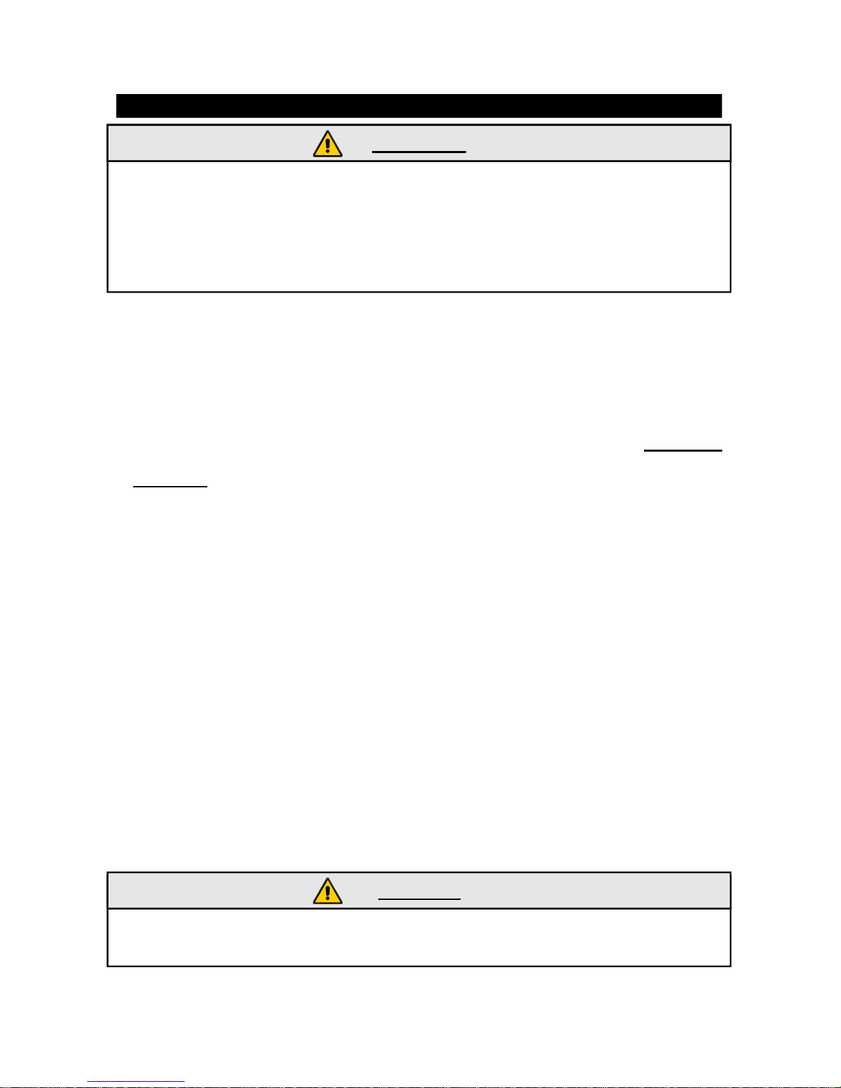
-ORANGE wire (INDICATOR Command): if the INDICATOR COMMAND is DISABLED
connect to the vehicle right indicators (or to the left). If the INDICATOR COMMAND function
is ENABLED with this wire is possible to command the indicators (only on the vehicles
equipped with this function - See the INDICATOR COMMAND diagram). For the connection
refer to the technical installation guides.
-Connect theORANGE/BLACK /wire (FEEDBACK) to the vehicle left (or right) indicator by
a diode(2 Amp) (see the INDICATOR COMMAND diagram).
-Connect the GREEN wire to the switches for the boot and bonnet protection.
-Connect the GREEN/BROWN wire to the original door pin switches. This alarm input is
set by default to manage the negative stable signals. It is possible to manage also the
vehicles original switches with negative impulsive signals(pulsing) enabling the Function
No.6 PULSING management. For the connection refer to the technical installation guides.
It is possible to manage also the positive stable signals enabling the Function No.7
Postive Door pin switch management.
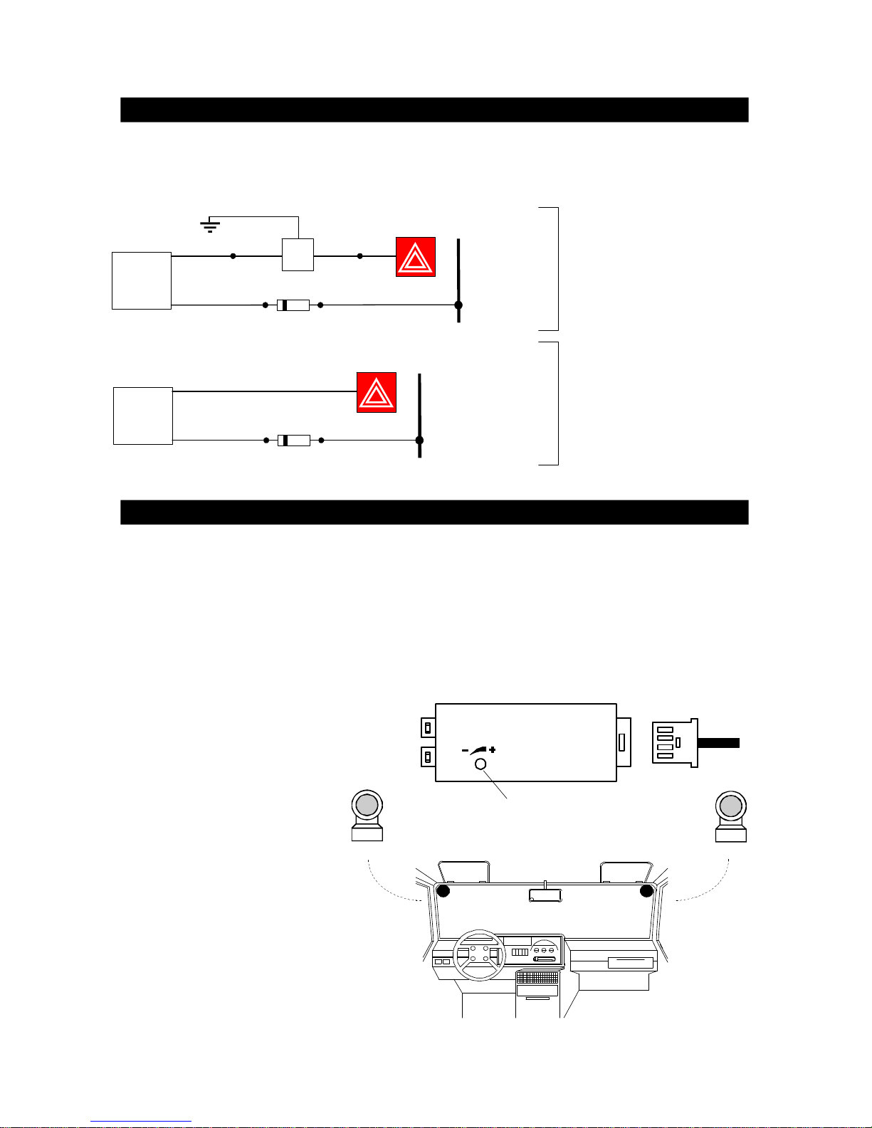
-Connect the PINK wire (Positive output when the alarm is armed - Max capacity 80 mA to
the PINK wire of modules or additional sensors (i.e. ultrasonic module).
-Connect the GREEN/BLACK wire (alarm input by optional additional sensors) to the
GREEN/BLACK wire of the same (i.e. ultrasonic module).
-Connect the BROWN wire (Sec. 0,35mm²) to the modules or additional sensors (i.e.
ultrasonic module).
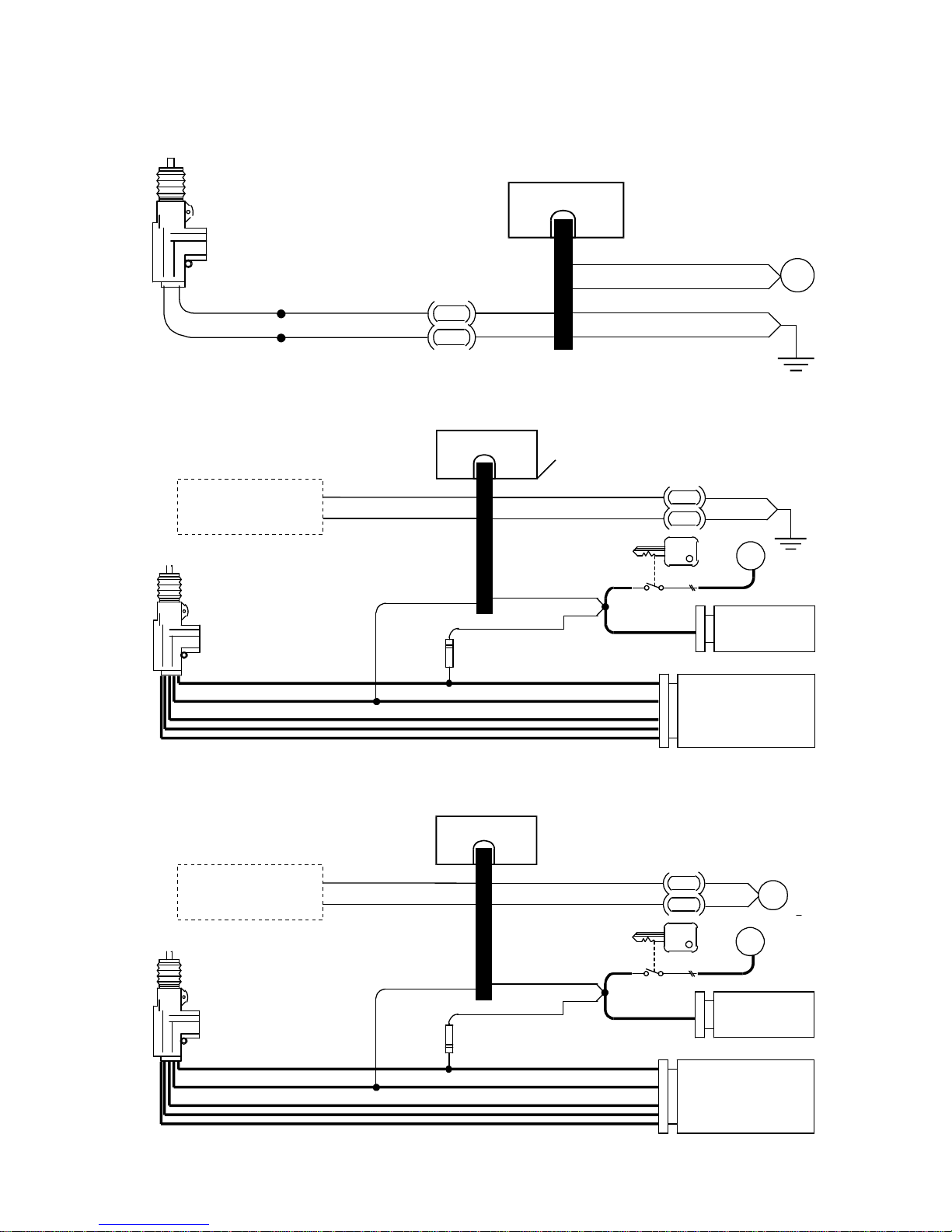
-TheRED/BROWN,RED/GREY,RED/BLUE,YELLOW/BROWN,YELLOW/GREYandYELLOW/
BLUE wires are used to command the central door locking referring to the instuctions in
the technical installation guide.
WARNING:
- Always use 5 A fuses on the RED/BLUE and YELLOW/BLUE wires.
- The max. load to command the central door locking is 5 A. For example it is not
possible to drive directly No.4 GT71 actuators (see diagramNo. 5).