GFA FG 40-31,75 Ex User manual

f
Pos: 1 /BA_Module_Manue ll/MAL_Fangvorr ichtungen FG 40-120/01_Dec kblatt/01_Deckb latt_ATEX_00000_ M002 @ 21\mod_1479899122976_ 28.docx @ 1020557 @ @ 1
Installation instructions
Safety brake
FG 40-31,75 Ex
For use in potentially explosive atmospheres (Ex)
Type: 10005266 00001
Pos: 2 /BA_Module/BA_Sei tenumbruch @ 0\mod_119071 9383361_0.docx @ 550 @ @ 1
-en-
Version: 06.03.2020

2
Pos: 1 /BA_Module_Manue ll/MAL_Fangvorr ichtungen FG 40-120/02_L eerseite/02_Leersei te_00000_M001 @ 10\ mod_1363019735654_28. docx @ 785354 @ @1
GfA ELEKTROMATEN GmbH & Co. KG
Wiesenstraße 81 • 40549 Düsseldorf
www.gfa-elektromaten.de
Pos: 2 /BA_Module/BA_Sei tenumbruch @ 0\mod_119071 9383361_0.docx @ 550 @ @ 1

3
Pos: 1 /BA_Module_Manue ll/MAL_Fangvorr ichtungen FG 40-120/03_I nhaltsverzeichni s/03_Inhaltsver zeichnis_00000_M001 @ 10\ mod_1365773855193_28. docx @ 788345 @ @ 1
Table of contents
1General safety information .............................................................................................. 4
2Technical data ................................................................................................................ 5
3Technical data of limit switch / switch for manual operation ............................................. 5
4Function .......................................................................................................................... 6
5Mechanical installation .................................................................................................... 7
6Electrical installation ..................................................................................................... 11
7Safety brake activation .................................................................................................. 12
8Repairs ......................................................................................................................... 13
9Completion of initial operation / inspection .................................................................... 14
10Declaration of conformity .............................................................................................. 15
11Declaration of conformity .............................................................................................. 16
12Konformitätserklärung Zubehör ..................................................................................... 17
Pos: 2 /BA_Module/BA_Sei tenumbruch @ 0\mod_119071 9383361_0.docx @ 550 @ @ 1
Symbols
Warning - Potential injury or danger to life!
Warning - Danger to life from electric current!
Note - Important information!
▶ Requirement - Required action!
Schematic representations are based on product examples. Deviations from delivered
products are possible.

4
Pos: 1 /BA_Module_Manue ll/MAL_Fangvorr ichtungen FG 40-120/04_Si cherheitshinweise/ 04_Sicherheits hinweise_ATEX_0000 0_M001 @ 21\mod_14798996651 57_28.docx @ 1020587 @ 1 @ 1
1General safety information
Specified normal use
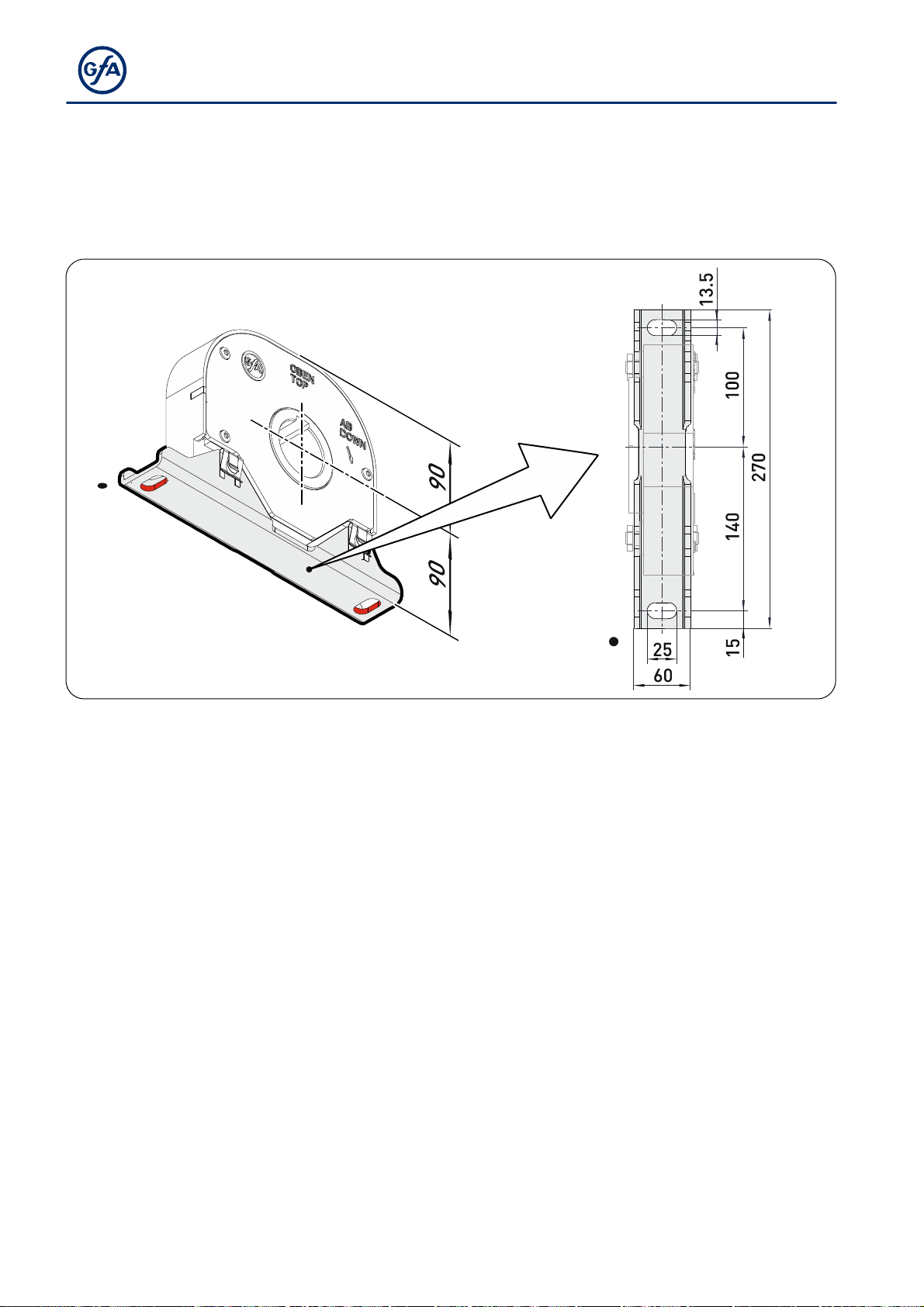
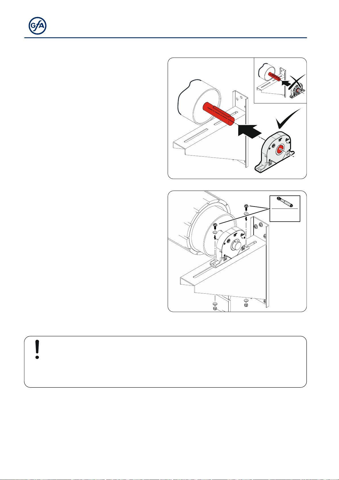
The safety brake is intended for loads which must be secured against falling down. The
device can be used in potentially explosive atmospheres according to the ATEX directive
2014/34/EU. The safety brake is mounted directly onto the shaft. The safety brake is
activated automatically in the case of trapping. The function depends on speed and rotary
direction. The safe operation is only guaranteed with specified normal use. No liability for
damage caused by other applications or non-observance of the information in the manual.
Modifications are only permitted with the agreement of the manufacturer. Otherwise the
Manufacturer’s Declaration shall be rendered null and void.
Safety information
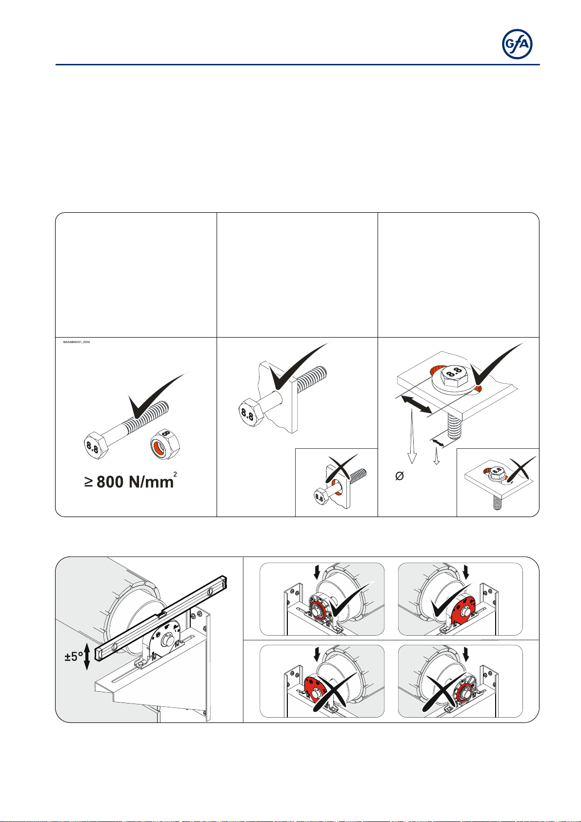
Installation and commissioning are to be carried out by skilled personnel only.
Only trained electrical craftsmen are permitted to work on electrical equipment. They must
assess the tasks assigned to them, recognise potential danger zones and be able to take
appropriate safety measures.
Installation work is only to be carried out with the supply off.
Observe the applicable regulations and standards.
Coverings and protective devices
Do not operate unless corresponding coverings and protective devices are installed.
Ensure that cable glands are correctly tightened.
Spare parts
Only use original spare parts.
Pos: 2 /BA_Module/BA_Sei tenumbruch @ 0\mod_119071 9383361_0.docx @ 550 @ @ 1

5
Pos: null /BA_Module _Manuell/MAL_Fangvor richtungen FG 40-120/0 5_Technische Daten/ 05_Technische_Date n_FG_040-31,75_A TEX_00000_M001 @ 32\mod_1581 589316035_28.doc x@ 157 9264 @ 11 @ 1
2Technical data
Series FG 40-31,75 Ex
Explosion protection II 2G c IIC T3
Max. torque 400 Nm
Output / hollow shaft (Ø) 31,75 mm
Locking torque 1150 Nm
Safety brake (approval number) TorFV 3/009
Maximum operating speed
OPEN / CLOSE 24 / 24 rpm
Admissible bearing load Fmax 3000 N
Keyway width 8 mm
Keyway height 33.3 mm
Degree of protection IP 65
Admissible temperature range -20 / +40 °C
3Technical data of limit switch / switch for manual operation
Type 07-2511-113001
Manufacturer Bartec
Explosion protection II 2G Ex d IIC T6
II 2D Ex tD A21 IP 66 T80°C
Test certificate G: PTB 00 ATEX 1093
D: IBExU01 ATEX 1007
Supply voltage 400 V
Temperature range -20 / +40 ° C
Degree of protection IP 66
Attention – Damage to components!
The maximum allowable current applied to the switch is
2A 400V for AC-15 and 0.15 250V for DC-13.
Pos: null /BA_Module/BA_ Seitenumbruch @ 0\ mod_1190719383361_0.d ocx @ 550 @ @1

6
Pos: 1 /BA_Module_Manue ll/MAL_Fangvorr ichtungen FG 40-120/06_F unktionsbeschrei bung Montage Fangfall/06_ Funktionsbeschr eibung_Montage_Fangf all_ATEX_00000_ M001( 2020-02-18 08:06:24) @13\mod_13 89279129057_28.doc x@ 8266 50 @ 11111 @ 1
4Function
1 Hollow shaft
2 Safety switch
/
Line
3 Plunger
4 Floating foot
5 Cover (aluminium)
Fmax Permissible bearing
(see technical data)
In normal operation, the safety brake functions similar to pedestal bearings. The safety brake
is tripped as soon as the maximum operating speed in DOWN direction is exceeded. This
results in the following reactions:
The shaft is blocked in DOWN direction (➊).
The safety switch is actuated to interrupt the control current (➋).
Release is optically indicated by a red plunger (➌).
Operating position: Braking position:

7
5Mechanical installation
Requirements
The permissible loads on walls, mountings, connection and transmission elements must not
be exceeded even for maximum locking torque (▶ observe technical data).
Connection elements:
▶ Use self-locking
connection elements with
a minimum strength of
800 N/mm2 (8.8).
▶ Use a screw that
precisely fits the hole.
▶ Use adequately
dimensioned washers for
elongated holes.
BAGAB00002_Z002 BAGAB00003_Z002
3 : 1
Permissible mounting positions
BAGAC09001_Z001
Ab
Down
Ab
Down
Ab
Down
Ab
Down

8
Mounting
2 elongated holes are provided for mounting.
BAGAD09001_Z001

9
Installation
The following descriptions refer to a facility or door which is not further defined. The facility or
door manufacturer's specifications must also be observed.
Warning – Injury or danger to life possible!
Use a lifting device with sufficient load-carrying capacity for installation tasks.
▶ Completely grease the door shaft.
BAGAE01001_Z003
▶ Mount the key.
BAGAE03002_Z001

10
▶ Attach safety brake. Observe rotating
direction.
BAGAE09001_Z001
▶ Tighten all connection elements (M12) with
a torque of 75 Nm. Install all further
connection elements according to the
specifications of the door or facility
manufacturer.
75 Nm
8.8
8.8
BAGAE09002_Z001
Note
If the safety brake has been tripped during installation, follow the procedure
described under
Safety brake activation
.

11
6Electrical installation
Warning – Danger to life due to electrical current!
Disconnect the cables (mains OFF) and check that the supply is off
Observe applicable regulations and standards
Ensure proper electrical connection
Use suitable tools
The integrated safety switch of the safety brake functions as an NC contact. Connect the
cable of the safety switch to the EMERGENCY STOP input of the door control. When the
safety brake is activated, the electrical circuit is interrupted and the electrical operation of the
gate is no longer possible.
Carrying out the electrical installation
Cable of the safety brake's safety switch (➊) Connection of the cable to the
EMERGENCY STOP input of the door
control (➋)
Warning – Injury or danger to life possible!
The safety switch of the safety brake must not be connected to the drive unit.
Completing the electrical installation
Install cable entries and/or cable glands.

12
7Safety brake activation
The safety brake is tripped as soon as the
maximum operating speed in DOWN
direction is exceeded. This results in the
following reactions:
The shaft is blocked in DOWN direction
(➊).
The safety switch is actuated to interrupt
the control current (➋).
Release is optically indicated by a red
plunger (➌).
Warning!
De-energise the facility and secure against unintended switching-on.
Secure door/load against falling.
Rectify the cause of tripping (drive unit, chain, etc.).
Any time the safety brake has been tripped, it must be disassembled and checked. If the
control pointer (➊) is damaged, the safety brake must be replaced.
Unscrew (3xT20)
cover (aluminium)
and assess control
pointer (➊).
Control pointer
broken. ⇨ Ⓐ
Replace safety
brake!
Control pointer
damaged. ⇨ Ⓑ
Replace safety
brake!
Control pointer not
damaged. ⇨ Ⓒ
Repair safety brake.

13
8Repairs
If the control pointer is not damaged (see
Safety brake activation
– Ⓒ), the safety brake can
be repaired.
▶ Rotate hollow shaft in OPEN direction by
approx. 90°.
90°
▶ Press the red plunger back into the
housing.
▶ The safety brake is ready for operation
again.
Pos: 2 /BA_Module/BA_Sei tenumbruch @ 0\mod_119071 9383361_0.docx @ 550 @ @ 1

14
Pos: 1 /BA_Module_Manue ll/MAL_Fangvorr ichtungen FG 40-120/07_A bschluss Inbetri ebnahme Prüfung/07_Absc hluss Inbetriebnah me_Prüfung_00000_ M001 @ 10\mod_136274717 0240_28.docx @ 785300 @ 1 @ 1
9Completion of initial operation / inspection
Check the following components and after that, mount all covers.
Mounting
Check all mounting elements (consoles, screws, retaining rings etc.) for tightness and
impeccable condition.
Electric wiring
Check connection cables and cables for damage or pinches.
Check screw and plug connections for correct seating and electrical contact.
Mounting position
On the basis of the OBEN/TOP and AB/DOWN markings and by checking.
Maintenance/inspection
The safety brake requires no maintenance.
The safety brake is type-approved. Checking for correct functioning is not required and
inadmissible once the safety brake is installed.
Entire safety brake
Note!
Have a specialist check the safety brake once a year.
Shorter inspection interval for frequently used equipment or doors.
Observe the applicable regulations and standards
=== Ende der Liste für TextmarkeInhal t= ==
Warning – Injury or danger to life possible!
Do not activate the safety brake without having connected the safety switch!

15
Pos: 2 /BA_Module_Manue ll/MAL_Fangvorr ichtungen FG 40-120/08_ Herstellererklär ung/08_Herstellerer klärung_M003 @ 26\mod_1 535448931132_28. docx @ 1091178 @ @ 1
10 Declaration of conformity
Declaration of conformity
within the meaning of Machinery Directive 2006/42/EC
within the meaning of RoHS Directive 2011/65/EU
We,
GfA ELEKTROMATEN GmbH & Co. KG
declare under our sole responsibility that the
following product complies with the above
directives and is only intended for installation in a
door system.
Safety brake
FG 40-31,75 Ex
Part no.: 10005266 00001
Authorised representative to compile the
technical documents is the undersigned.
Düsseldorf, 10.08.2018
Stephan Kleine
CEO
Signature
Standards applied:
EN 12604:2017
Industrial, commercial and garage doors and
gates - Mechanical aspects - Requirements
EN 12605:2000
Industrial, commercial and garage doors and
gates - Mechanical aspects - Test methods
EN 60204-1:2006
Safety of machinery - Electrical equipment of
machines - Part 1: General requirements
Pos: 3 /BA_Module/BA_Sei tenumbruch @ 0\mod_119071 9383361_0.docx @ 550 @ @ 1

16
Pos: 1 /BA_Module_Manue ll/MAL_Fangvorr ichtungen FG 40-120/09_ Konf ormitätserkläru ng_Ex/09_Konfor mitätserklärung_Ex_ T3_M003 @ 26\mod_1535448 978159_28.doc x@ 109126 6@ @ 1
11 Declaration of conformity
Declaration of conformity
within the meaning of Explosion Protection Directive 2014/34/EU
regarding the safe assembly of components
We,
GfA ELEKTROMATEN GmbH & Co. KG
declare under our sole responsibility that the
following module complies with the above
directive and that no new hazards arise from
assembly. The assembled modul are only
intended for installation in a door system.
Safety brake
FG 40-31,75 Ex
Part no.: 10005266 00001
Consisting of:
Safety brake FG 40-31,75 Ex
Safety switches: 07-2511
Higher-level product identification code
II 2G c IIB T3
Authorised representative to compile the
technical documents is the undersigned.
Düsseldorf, 10.08.2018
Stephan Kleine
CEO
Signature
Pos: 2 /BA_Module/BA_Sei tenumbruch @ 0\mod_119071 9383361_0.docx @ 550 @ @ 1

17
Pos: 1 /BA_Module_Manue ll/MAL_Fangvorr ichtungen FG 40-120/10_ Konf ormitätserkläru ng_Ex_Baugruppen/ 09_Konformitätser klärung_Ex_Baugruppe n_M001 @ 13\mod_1387288 740748_28.docx @ 825667 @ @ 1
12 Konformitäts erklärung Zubehör
Pos: 2 /BA_Module/BA_Sei tenumbruch @ 0\mod_119071 9383361_0.docx @ 550 @ @ 1

18
Pos: 1 /BA_Module_Manue ll/MAL_Fangvorr ichtungen FG 40-120/11_K onformitätserk lärung_Ex_Fertigungsk ontrolle/10_Konf ormitätserklär ung_Ex_T3_Fertigung skontrolle_M003 @ 26\ mod_1535449088667_28. docx @ 1091420 @ @ 1
Declaration of conformity
within the meaning of Explosion Protection Directive 2014/34/EU
We,
GfA ELEKTROMATEN GmbH & Co. KG
declare under our sole responsibility that the
following module complies with the above
directive and that no new hazards arise from
assembly. The assembled modul are only
intended for installation in a door system.
Safety brake
FG 40-31,75 Ex
Part no.: 10005266 00001
Authorised representative to compile the
technical documents is the undersigned.
Düsseldorf, 10.08.2018
Stephan Kleine
CEO
Signature
Identification of the product according to
Directive: II 2G c IIB T3
Notified body pursuant to Directive:
TÜV Nord Anlagetechnik GmbH
Am TÜV 1
30519 Hannover, Deutschland
Registration number: 8000313442
Standards applied:
EN 13463-1:2009
Non-electrical equipment for use in potentially
explosive atmospheres – Part 1: Basic method
and requirements
EN 13463-5:2011
Non-electrical equipment intended for use in
potentially explosive atmospheres – Part 5:
Protection by constructional safety ‘c’
Pos: null /BA_Module/BA_ Seitenumbruch @ 0\ mod_1190719383361_0.d ocx @ 550 @ @1

19
Pos: null /BA_Module/BA_ Seitenumbruch @ 0\ mod_1190719383361_0.d ocx @ 550 @ @1

20
=== Ende der Liste für TextmarkeInhal t1= ==
Table of contents