GHM Delta OHM HD2050 User manual

Operating manual
Omnidirectional sound source
HD2050
Power amplifier/noise generator
HD2050.20
Facade directional loudspeaker
HD2050.30
www.deltaohm.com
English
Ke
ep for future
referen
ce.

HD2050 - 2 - V1.4
INDEX
1 INTRODUCTION .................................................................................................... 3
2 DESCRIPTION ....................................................................................................... 4
2.1 ELECTRICAL CONNECTIONS AND POWER ON .................................................................. 6
2.1.1 HD2050 DODECAHEDRON + HD2050.20 AMPLIFIER ................................................. 6
2.1.2 HD2050.30 FACADE LOUDSPEAKER + HD2050.20 POWER AMPLIFIER ............................ 7
2.1.3 HD2050 DODECAHEDRON + HD2050.40 SU WOOFER + HD2050.20 AMPLIFIER .............. 7
2.1.4 HD2050.30 FACADE LOUDSPEAKER + HD2050.40 SU WOOFER + HD2050.20 AMPLIFIER .. 9
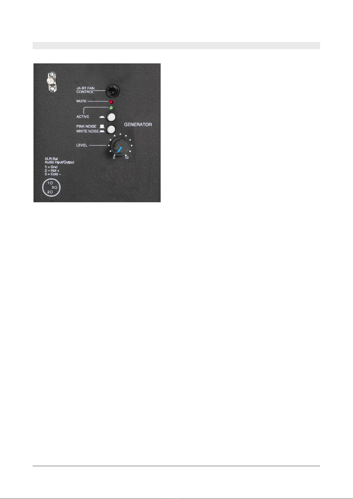
2.2 NOISE GENERATOR ............................................................................................ 10
2.3 POWER AMPLIFIER AND DSP (DIGITAL SIGNAL PROCESSOR) ........................................... 11
2.4 HD2050.20R REMOTE CONTROL KIT ....................................................................... 13
2.5 HD2050.1 STAND ............................................................................................ 14
2.6 HD2050.40 SU WOOFER .................................................................................... 14
2.7 HD2050.30 FACADE LOUDSPEAKER ........................................................................ 15
3 CONNECTORS FOR REMOTE MANA EMENT ......................................................... 17
4 USIN PODWARE SOFTWARE ............................................................................. 18
4.1 CREATE A USER CONFIGURATION AND LOAD INTO THE DSP .............................................. 18
5 TECHNICAL SPECIFICATIONS ............................................................................. 21
6 HD2050 – DIRECTIVITY (ISO 140 – ISO 3382) .................................................. 23
6.1 HD2050.30: SOUND POWER LEVEL ........................................................................ 25
6.2 HD2050.30: DIRECTIVITY .................................................................................. 25
7 ORDERIN CODES .............................................................................................. 26

HD2050 - 3 - V1.4
1INTRODUCTION
The system is composed of dodecahedron loudspeaker HD2050, digital power amplifier
HD2050.20 and related accessories; it allows to perform building and architectural acoustics
measurements:
•Acoustic insulation
•uildings acoustics
•Acoustic absorption
•Reverberation time
•Room acoustics ( RASTI, STI, Clarity, Definition descriptors etc.)
•Risposta all’impulso
HD2050 is a sound source able to emit sound energy in the room in a isotropic way with very
high very high sound power levels. The HD2050 sound source is designed to offer maximum
performances with special attention to international standards in the field of architectural and
building acoustics.
The standards it complies with, are EN ISO 140-3:2006 and EN ISO 3382:2001 as concerns di-
rectivity; .
HD2050 features a wide extension frequency response and provides an emission sound power
level of more than 122d re 1pW. Twelve coaxial loudspeakers arranged on the dodecahedron
faces, provide a high acoustic performance. The twelve faces cabinet is multilayer wood made
and has a light weight allowing an optimal on site portability. The double components plastic
coating VFI-2513 gives the case a high hardness, so to conform ASTM (American Society for
Testing Materials) standards. A further opaque geal-coat finish makes the cabinet surface
scratch and waterproof resistant.

HD2050 - 4 - V1.4
2DESCRIPTION
The HD2050.20 is a digital signal amplifier, designed to work with HD2050 and HD2050.30
sources to obtain from these maximum acoustic performances.
The HD2050.20 amplifier incorporates a white / pink noise generator and an auxiliary input to
receive signals from other external devices.
Using Podware software (downloadable from Delta OHM website) you can modify the EQ curve
stored in the amplifier’s DSP in order to tailor the frequency response of the system to specific
measurement needs.
It’s also possible to connect the HD2050.30 façade loudspeaker or the HD2050.40 sub-woofer
(matched to the source HD2050) to HD2050.20 amplifier.
The system can be both AC and DC current supplied.

HD2050 - 5 - V1.4
For the connection of the HD2050.20 amplifier refer to connectors description shown in the
picture below.
HD2050.20 amplifier front panel
enerator section (above)
and amplifier section (below)
panel
Output conne
c
tor
(signal to loud-
speaker)
AC line input
Mains and Power
ON
Switch user DSP
Amplifier I
n
put
connector
Switch presets
Pink/
Whit
e no
i
se
selector
Manual signal
activation
Noise
generator
se
c
tion
Amplifier
section
Level control
0 = MIN
Antenna
connector

HD2050 - 6 - V1.4
2.1 ELECTRICAL CONNECTIONS AND POWER ON
elow typical connection configurations.
2.1.1 HD2050 DODECAHEDRON + HD2050.20 AMPLIFIER
efore making any connections make sure that the "LEVEL" potentiometer is set to minimum
by turning the knob all the way counterclockwise (position 0).
Set the PRESET switch on JA12 position for use with HD2050 dodecahedron (switch position on
JA4012 for use with HD2050.30 loudspeaker).
If user needs a custom equalization, set the switch "User DSP" to ON. To create, edit and load
in the DSP a custom equalization refer to the section on page 18.
Connect the L-shaped cable-adapter (HD2050.1.L) to HD2050 dodecahedron.
Connect the Neutrik SPEAKON signal cable to L-shaped cable-adapter (dodecahedron side) and
to the “OUTPUT” amplifier connector.
Connect the power cord to the mains socket and to the AC LINE INPUT of the amplifier.
The amplifier-side power cord connector (Neutrik POWERCON) also acts as power switch of the
equipment. Once the POWERCON connector is plugged in, rotate the connector about 45°
clockwise in order to turn on the amplifier.
ROTATE CLOCKWISE TO TURN ON AMPLIFIER

HD2050 - 7 - V1.4
2.1.2 HD2050.30 FACADE LOUDSPEAKER + HD2050.20 POWER AMPLIFIER
efore making any connections make sure that the "LEVEL" potentiometer is set to minimum
by turning the knob all the way counterclockwise (position 0).
Set the PRESET switch on JA4012 position for use with HD2050.30 loudspeaker.
If user needs a custom equalization, set the switch "User DSP" to ON. To create, edit and load
in the DSP a custom equalization refer to the section on page 18.
Connect the L-shaped cable-adapter (HD2050.1.L) to HD2050.30 loudspeaker.
Connect the Neutrik SPEAKON signal cable to L-shaped cable-adapter (loudspeaker side) and
to the “OUTPUT” amplifier connector.
Connect the power cord to the mains socket and to the AC LINE INPUT of the amplifier.
The amplifier-side power cord connector (Neutrik POWERCON) also acts as power switch of the
equipment. Once the POWERCON connector is plugged in, rotate the connector about 45°
clockwise in order to turn on the amplifier.
ROTATE CLOCKWISE TO TURN ON AMPLIFIER
2.1.3 HD2050 DODECAHEDRON + HD2050.40 SUBWOOFER + HD2050.20 AMPLIFIER
efore making any connections make sure that the "LEVEL" potentiometer is set to minimum
by turning the knob all the way counterclockwise (position 0).
Set the PRESET switch on JA12 position for use with HD2050 dodecahedron.
If user needs a custom equalization, set the switch "User DSP" to ON. To create, edit and load
in the DSP a custom equalization refer to the section on page 18.

HD2050 - 8 - V1.4
Connect the L-shaped cable-adapter (HD2050.1.L) to HD2050 dodecahedron.
Connect the short Neutrik SPEAKON signal cable (2 m cable HD2050.1.2) to L-shaped cable-
adapter (dodecahedron side) and to HD2050.40 subwoofer using one of the two inputs (no
matter which one).
Connect the Neutrik SPEAKON signal cable (5 m cable HD2050.1.5): one side to the second
subwoofer input, the other side to the “OUTPUT” amplifier connector.
Connect the power cord to the mains socket and to the AC LINE INPUT of the amplifier.
The amplifier-side power cord connector (Neutrik POWERCON) also acts as power switch of the
equipment. Once the POWERCON connector is plugged in, rotate the connector about 45°
clockwise in order to turn on the amplifier.
ROTATE CLOCKWISE TO TURN ON AMPLIFIER

HD2050 - 9 - V1.4
2.1.4 HD2050.30 FACADE LOUDSPEAKER + HD2050.40 SUBWOOFER + HD2050.20 AMPLIFIER
efore making any connections make sure that the "LEVEL" potentiometer is set to minimum
by turning the knob all the way counterclockwise (position 0).
Set the PRESET switch on JA4012 position for use with HD2050.30 loudspeaker.
If user needs a custom equalization, set the switch "User DSP" to ON. To create, edit and load
in the DSP a custom equalization refer to the section on page 18.
Connect the L-shaped cable-adapter (HD2050.1.L) to HD2050.30 loudspeaker.
Connect the short Neutrik SPEAKON signal cable (2 m cable HD2050.1.2) to L-shaped cable-
adapter (facade loudspeaker side) and to HD2050.40 subwoofer using one of the two inputs
(no matter which one).
Connect the Neutrik SPEAKON signal cable (5 m cable HD2050.1.5): one side to the second
subwoofer input, the other side to the “OUTPUT” amplifier connector.
Connect the power cord to the mains socket and to the AC LINE INPUT of the amplifier.
The amplifier-side power cord connector (Neutrik POWERCON) also acts as power switch of the
equipment. Once the POWERCON connector is plugged in, rotate the connector about 45°
clockwise in order to turn on the amplifier.
ROTATE CLOCKWISE TO TURN ON AMPLIFIER

HD2050 - 10 - V1.4
2.2 NOISE ENERATOR
Fig. 2.2.1 – Noise enerator section of HD2050.20 amplifier
The noise generator has two buttons: one is used to activate the noise generator (ACTIVE);
the other one is used to select the type of noise, between white noise and pink noise, sent to
amplifier
The green led “active” indicates that the generator’s status is ON.
y the external transmitter of the embedded remote control kit, the “mute” is activated, inter-
rupting immediately the generated noise. When the “mute” is activated, the cooling fan of the
amplifier’s power section, will be turned OFF for some seconds; in this way it’s avoided that
the noise generated by the fan could influence the acoustic measurement, if the background
noise level is considerably low
If the optional battery power kit (kit with inverter for battery power supply of apparatus when
mains power supply is not available) is used, it is possible to use the JA- T FAN CONTROL
connector to drive the power OFF of cooling fan installed in the battery power kit.
The noise generator emission level is manually adjusted using the “LEVEL” potentiometer. In
this way it’s possible to send the requested signal level to amplifier’s input. When the potenti-
ometer is rotated to the maximum clockwise (indication 10), the generator’s output level is
equal to the maximum allowed level of HD2050.20 amplifier’s input.

HD2050 - 11 - V1.4
2.3 POWER AMPLIFIER AND DSP (DI ITAL SI NAL PROCESSOR)
Fig. 2.3.1 –PRESETS, User DSP sections and amplifier connectors
HD2050.20 power amplifier uses a Digital Signal Processor with two different selectable
“presets”; the needed preset can be activated using the “PRESETS” switch on the amplifier’s
front panel.
The preset settings allow optimum operation of the amplification system with the use of the
dodecahedral source HD2050 or when the HD2050.30 facade loudspeaker is used
1. PRESET JA12: dodecahedral sound source HD2050 (with or without HD2050.40 sub)
2. PRESET JA4012: facade insulation loudspeaker HD2050.30
The two presets cannot be modified by the user and are loaded as factory default when the
system is delivered to customers. They include correct frequency cuts and optimal setup
(limiter) of input signal amplitude in order to obtain the maximum system performance
without the risk to damage electronic components.
The two “presets” are very different each other and are studied to be used with specific
loudspeakers models. For a correct loudspeaker response and mostly in order to avoid any
damage, it’s compulsory to use the correct preset for each loudspeaker connected to the
system.
A second switch named “User DSP” allows to activate and load on the system a correction
curve to equalize the acoustic response of the loudspeaker. The correction curve works “over”
the selected preset. The equalization curve “User DSP” can be created and modified by the
user, through the PodWare PC software program supplied with the amplifier HD2050.20. After
equalization creation and modification the curve can be loaded on the amplifier’s DSP through
the serial interface (US connector on the front panel). The user defined equalizations can be
stored on the PC memory (file with *.dse extension) and when used are loaded on amplifier’s
DSP.

HD2050 - 12 - V1.4
When the switch “User DSP” is set to ON, it will be activated the last equalization curve
present while PC connected. If the switch is set to OFF , the “User DSP” is disabled and the
response curve will be the “presets” currently active.
The three led on the front panel have the following functions:
1. yellow (ON): amplifier’s power ON status
2. green (signal): signal present on the amplifier’s input (whether it comes from the in-
ternal noise generator and from an external device)
3. red (limit): signal limiter active.
The limiter is set to drive the different loudspeakers (HD2050 and HD2050.30) at their
maximum performances avoiding possible damage. When external signals are used, it’s
possible to increase the level until the limiter acts occasionally; it is not recommended to go
above this threshold in order to avoid distortion on the signal.
HD2050.20 is based on switching technology and it is capable to deliver 1250 W per channel
on 2 ohm. When used with HD2050.30 (two ways) façade loudspeaker ,the two available
channels amplify the two speakers in bi-amp mode. If connected to HD2050 dodecahedron,
the channel 2 is used for amplification. The channel 1 is dedicated to HD2050.40 subwoofer
amplification. It’s possible to use the dodecahedron alone without subwoofer connected. For
audio output, on the front panel there is a female 4poles SpeakON connector with the following
pin-out:
Switch PRESET OUTPUT 1+1- OUTPUT 2+2-
JA12 HD2050.40 HD2050
JA4012 HD2050.30 low freq. HD2050.30 high freq.
The kit is delivered with a small 4-pole L-shaped cable-adapter with SpeakON male and female
connectors. The male connector must be always connected to HD2050 dodecahedron or
HD2050.30 facade loudspeaker in order to adapt their internal connections. It is compulsory to
always connect this adapter in cascade with the usual 4 poles signal cable, in order to avoid
that the signal intended for subwoofer could conflict with some of the transducers mounted on
HD2050 and damage them.
It is strongly recommended to leave the L-shaped adapter connected to the dodecahedron. To
consider it integral part of dodecahedron, it is a safe way to avoid connections potentially
dangerous for the system.
Fig. 2.3.2 – L-Shaped adapter
When the L-shaped adapter is connected to dodecahedron, pay attention during the
transport, ensuring that it doesn’t touch the ground or hard surfaces so that the connector can
be damaged: eventually remove it temporarily. Remove the adapter when the dodecahedron is
placed in its carrying case.

HD2050 - 13 - V1.4
2.4 HD2050.20R REMOTE CONTROL KIT
The integrated HD2050.20R remote control kit allows to remotely control the internal noise
generator of HD2050.20.
This kit consists of a portable transmitter and an integrated receiver that can be activated at a
distance up to 100 m. Transmitter is supplied by batteries and is activated manually with a
button.
The receiver has an external antenna to be screwed directly on the specific input connector on
the front panel of HD2050.20 amplifier (generator section).
enerator section with integrated
remote control receiver
A
ntenna to be screwed
on HD2050.20 front
panel
T
ransmi
t
ter
Fig. 2.4.1 – Remote control parts
SMA
Antenna
Input
connector

HD2050 - 14 - V1.4
2.5 HD2050.1 STAND
Tripod with adjustable height and foldable. Extremely stable
and light weight, it is supplied with integrated wheels allow-
ing to translate the dodecahedron on the floor with no need
to dismount it.
HD2050.1 stand has a security system to slowdown the pole
when extended in order to avoid possible damage to dodeca-
hedron. It also has a lock system.
2.6 HD2050.40 SUBWOOFER
The HD2050.30 passive subwoofer is designed to work in
conjunction with the HD2050 dodecahedron. The system
consists of the sub HD2050.30, the dodecahedron HD2050
and the HD2050.20 digital power amplifier, allowing to
fulfill advanced requirements in applications as sound
insulation and architectural acoustics measurements.
Acoustic testing laboratories, manufacturers of materials
with high insulation properties, acoustic consultants with
specific measurement needs, or in general where it is
needed a big amount of acoustic energy at low and high
frequency, they will find the Delta OHM system a complete
and effective solution.
The HD2050.40 is a band-pass type; the sound radiation is
not direct but through a couple of resonant cavities, one
front and one rear. In this way the reproduction of the
low frequencies has the maximum efficiency, without
interfering with the other components of the system.
Thanks to the particular configuration, the speaker
membrane undergoes far less movement than in reflex
systems, significantly reducing distortion even at
maximum drive power.

HD2050 - 15 - V1.4
2.7 HD2050.30 FACADE LOUDSPEAKER
The HD 2050.30 façade loudspeaker is the ideal
tool to generate a uniform sound field on the front
of a building
It provides not only a high sound power emission
(into the range 70Hz-20KHz), needed in case of
high background noise, but also a uniform sound
distribution especially at high frequencies, guar-
anteed by the particular construction of the driver.
Thanks to this solution are substantially reduced
the phenomena of sound concentration, especially
on the high range, due to the directionality of
standard transducers when used close to the wall
and it is therefore improved the measurements
accuracy. The HD2050.30 loudspeaker can be
easily positioned in all typical situations of facades sound insulation tests. HD2050.30.2 sup-
port is designed to position the loudspeaker at 45° both on the ground and on the tripod, with
the latter system gaining valuable meters in front of the façade. The weight of 13.5Kg repre-
sents the best compromise between performance in sound emission and portability.
HD2050.30.2 support for 45° orientation
This accessory is designed to position the loud-
speaker at 45° orientation with respect to the
building facade as requested by the standards. A
special housing makes it possible to install the
support on the HD2050.1 tripod. This allows to
lift the facade loudspeaker from the ground up to
about 200 cm (maximum extension of the tri-
pod). The support allows to rotate the loudspeak-
er freely in the horizontal plane.
The HD2050.30 loudspeaker must be fixed to the HD2050.30.2
support using the screws by hand as shown in the figure
below.
Loudspeaker positioned at 45° by means of support
HD2050.30.2
Tripod
housing

HD2050 - 16 - V1.4
Mounting the loud-
speaker on the support
The support has two screws with knob for each side (see figure
above). The screw with the larger size is coupled to a female
thread in the rear panel of the case. The coupling hole is posi-
tioned under the compartment for electrical connectors. The
same type of connection is also present in the upper part of the
case.
The two screws with smaller knob, instead are used to disas-
semble the aluminum support in case of transport.
Once the loudspeaker is assembled with the support, it can be
positioned on the floor or installed on the stand (figure on the
left).
NB: When the loudspeaker is installed on the stand,
make sure that it is properly positioned with the legs ex-
tended; an incorrect positioning of the stand and the
loudspeaker may damage the instrument itself as well as
cause personal injury to user.
When the tripod is used with the pole to its maximum
extension make sure that the floor is sufficiently flat to
ensure the stability of the system.
The HD2050.30.2 aluminum support disassembled is divided in
three parts as shown in the figure below.
HD2050.30.1 support disassembled
The 2050.30 loudspeaker has 2 Speakon NL4 connectors on the back. Only pins 1+/1- of each
connector are connected.
Loudspeaker installed on
the tripod using
HD2050.30.2 support

HD2050 - 17 - V1.4
3CONNECTORS FOR REMOTE MANA EMENT
The US connector on the front panel of HD2050.20 amplifier, enables to connect the system
to a PC.
The connection allows to remotely control the amplifier’s DSP (Digital Signal Processor), to
modify some parameters or customize the frequency response of the system using the para-
metric equalizer.
To modify the DSP settings it is necessary to install and use PodWare PC software supplied on
CD with the amplifier. To use PodWare software it’s necessary to install the US driver sup-
plied on CD (for installation instructions please refer to software installation manual).
The two EtherCon connectors are dedicated for functions available when the system is used
with other amplified loudspeakers having DSP on board. Through these connectors, multiple
speakers with DSP on board, can be chained together and controlled individually with a single
software.
To remotely manage HD2050.20 amplifier from a PC the supplied software must be installed
on a PC running Windows operating system. The system also works on Apple computers run-
ning Windows in emulation or Leopard with oot Camp. The software requires DotNETV2SP1
Framework available on the supplied CD.
Once the software is installed (see installation manual), connect the US cable from
HD2050.20 US socket to PC US port and run PodWare software.
To connect to the amplifier go to menu etworks >> Add networks , and select the US port
detected by the system. Then click the red triangle icon that, upon connection, will turn to
green. The software provides a online help with detailed explanations of all the operations pos-
sible with the system.

HD2050 - 18 - V1.4
4USIN PODWARE SOFTWARE
HD2050.20 digital amplifier has an internal DSP which can be programmed using provided
PodWare software. Connecting the amplifier to a PC via the US cable it’s possible, in real
time, to perform the following operations: activate the mute, gain, 8-band parametric equaliz-
er + two shelving filters, HP and LP filters, delay. The created setups can be uploaded in the
HD 2050.20 amplifier simply retrieving them from PC.
The system’s response equalization function is particularly important in measures of both
building and architectural acoustics. The ISO 10140-5:2010 standard (measurement of sound insu-
lation of building elements - Requirements for test facilities and equipment) requires that the noise spec-
trum generated by the sound source in the emitting room is good enough to obtain an ade-
quate signal to noise ratio in the receiving room. Moreover, the noise generated in the room
from 100Hz bandwidth, must be such that there is a difference < 6d between adjacent bands
of 1/3 octave so providing a sufficiently flat spectrum in the emitting room.
Since real rooms have different absorption characteristics, even if are used sound sources hav-
ing a free field emission spectrum sufficiently smooth, it may be necessary to equalize the re-
sponse of the system directly on the field to meet the requirements of the mentioned above in-
ternational standard.
To this end, the PodWare software enables a quick adjustment of the system response.
System requirements:
To use the software, at least a 450 MHz Pentium processor and 128 M RAM are required. It is
required the presence in the system of Microsoft® .NET Framework 1.1 or .NET Framework 2.0.
If .NET Framework is not installed in the system, it is possible to download it from Microsoft
website.
4.1 CREATE A USER CONFI URATION AND LOAD INTO THE DSP
In order to store into the DSP a user configuration of the response curve, is not nec-
essary that the switch "user DSP" on the amplifier is set to ON. It s necessary that
the switch is turned ON to activate the stored curve.
To install on a PC PodWare software and communication driver required for operation, please
refer to the software manual.
To connect the PodWare software, connect the US cable from PC to HD2050.20 amplifier US
input.
Turn ON the amplifier and start PodWare software.
Verify that the communication port is the right one on the menu >> etwork >> ComPort.
When the driver is installed, the system assign a COM port. In order to check which port is
assigned by the system, go in Device manager in the PC control panel; under “Ports (COM and
LPT)” should appear for example USB BvNet Port (COM6). The indicated COM6 port is the
US input

HD2050 - 19 - V1.4
one to be used. The number of the COM port may vary according to PC configuration and the
number of COM ports available on the system.
Click on >> Network >> Go online
Under "Devices" appears a line with the name of DSP (JADSP1250). Double click on the line to
enable the connection with the DSP
It will appear a control windows with partial vision. Click the icon to activate the full view.
The full control window allows to access the equalization, mute, filtering an delay functions.
Equalization functions include 8 band-pass filters, represented with different colors; central
frequency, bandwidth and gain can be modified.
Under the band-pass filter section are available two additional “shelf” filters; low shelf, high
shelf, slope and gain can be modified by the user.
Under the “shelf” filters section are available also two high-pass and low-pass filters; cut
frequency and shape can be modified.
As soon as necessary adjustments have been applied to the system it’s possible to save such
configuration and recall it when needed.

HD2050 - 20 - V1.4
To save the equalization created go on menu >> File >> Save as
Select a folder and save settings with a name (extension *.dse).
To recall the equalization curve go on menu >> File >> Open
A warning message reminds you that, once recalled the EQ curve, this will replace the one cur-
rently installed into the amplifier’s DSP.
To activate the user equalization curve just created, in the HD2050.20 amplifier’s front panel,
set the User DSP switch to ON.
Amplifier is ready to work with the new EQ curve.
Switch User DSP
This manual suits for next models
2
Table of contents
Popular Speakers manuals by other brands

Rega
Rega P10 quick start guide

Federal Signal Corporation
Federal Signal Corporation SelecTone 300GC Installation and service instructions

Clever Acoustics
Clever Acoustics CS 56F user manual

APart-Audio
APart-Audio OVO8P manual

KEF
KEF Q100 installation manual

Federal Signal Corporation
Federal Signal Corporation DS100X Description, Specifications, and Installation Manual