Proprietary and Confidential
Contents
Chapter 1: Manual Overview ........................................................................................................ 3
Chapter 2: BUC 25W Introduction ............................................................................................... 5
BUC 25W ....................................................................................................................... 5
Features and Benefits .................................................................................................... 5
Available Models and Configurations.............................................................................. 6
Technical Data and Specifications.................................................................................. 7
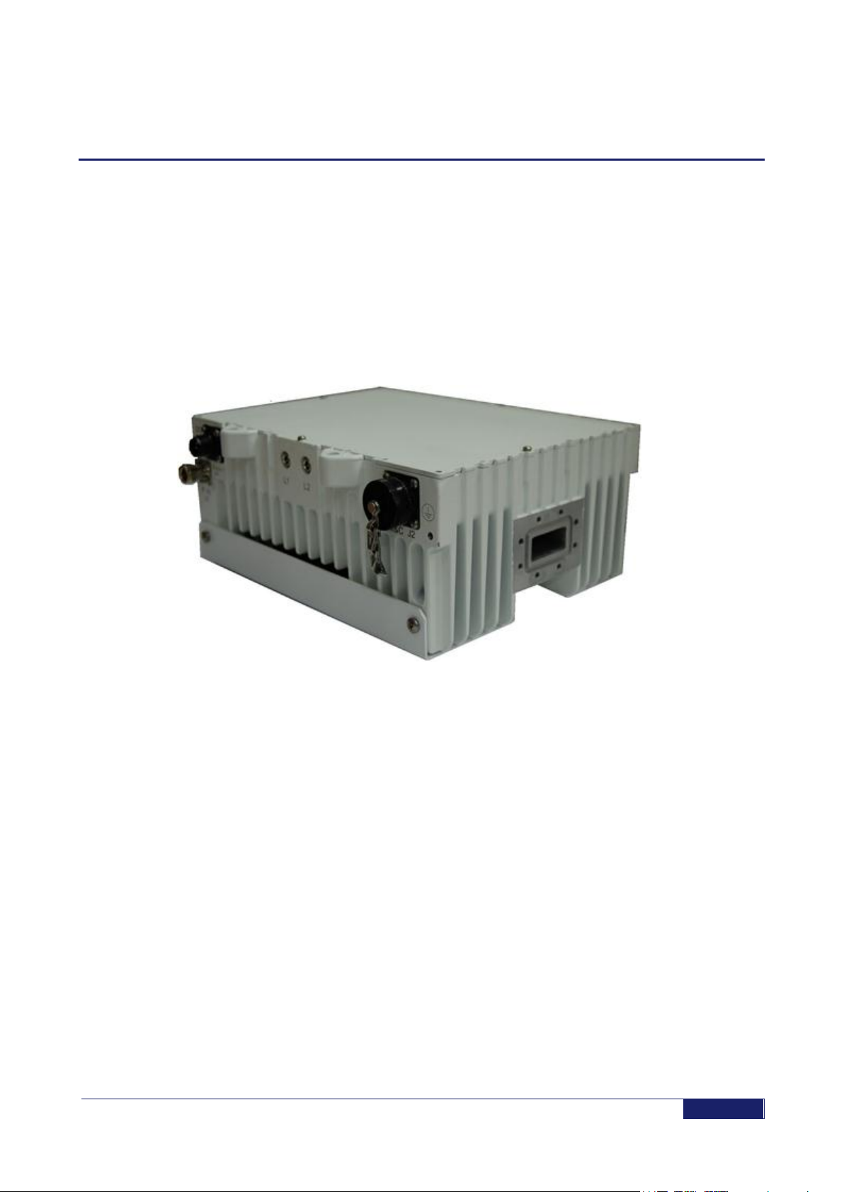
BUC Physical Description............................................................................................... 9
BUC 25W DC.............................................................................................................................9
BUC 25W AC...........................................................................................................................10
Chapter 3: Managing the System............................................................................................... 11
Handling....................................................................................................................... 11
Transportation..........................................................................................................................11
Storage.....................................................................................................................................11
Return of Equipment................................................................................................................12
Equipment Damage or Loss ....................................................................................................12
Receiving and Inspection.........................................................................................................12
Unpacking.................................................................................................................... 13
Unpacking Instructions.............................................................................................................13
BUC Packing List.....................................................................................................................14
Installation and Operation............................................................................................. 16
BUC 25W DC Mechanical Installation .....................................................................................16
BUC 25W AC Mechanical Installation .....................................................................................16
BUC 25W DC to External DC Source......................................................................................18
BUC 25W AC Indoor/Outdoor PS Cable Connections ............................................................19
Operation and Post Installation Checks...................................................................................19
Chapter 4: Maintenance ............................................................................................................. 21
Preventive Maintenance Activities................................................................................ 21
Corrective Maintenance................................................................................................ 21
Fan Replacement.....................................................................................................................21
Removing the Fan....................................................................................................................21
25W DC & AC Models Fan Removal.......................................................................................23
Troubleshooting............................................................................................................ 24