Gira 2914 Series User guide

Gira emergency set
2914 ..
Gira nurse call system
Installation, start-up, operation


3
11.2009/V 1.2
Table of Contents
1. Introduction ........................................................................................... 4
1.1 General information........................................................................................ 4
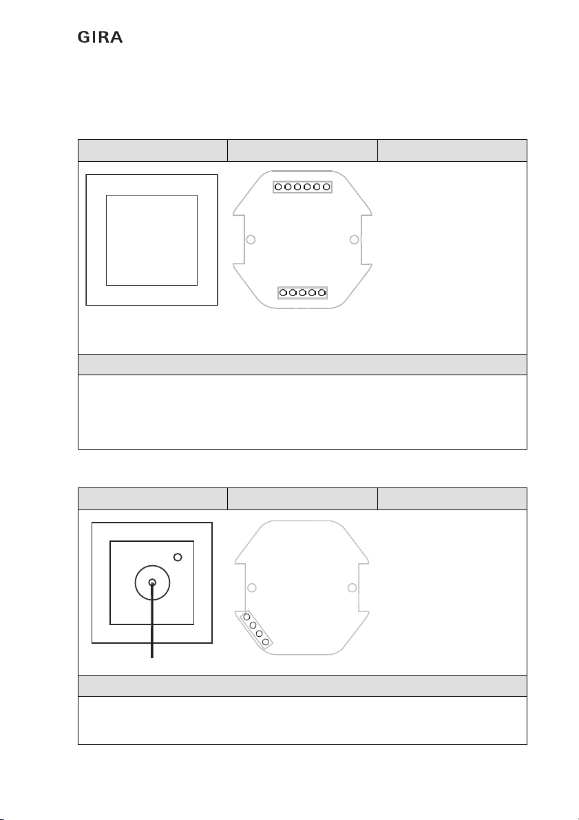
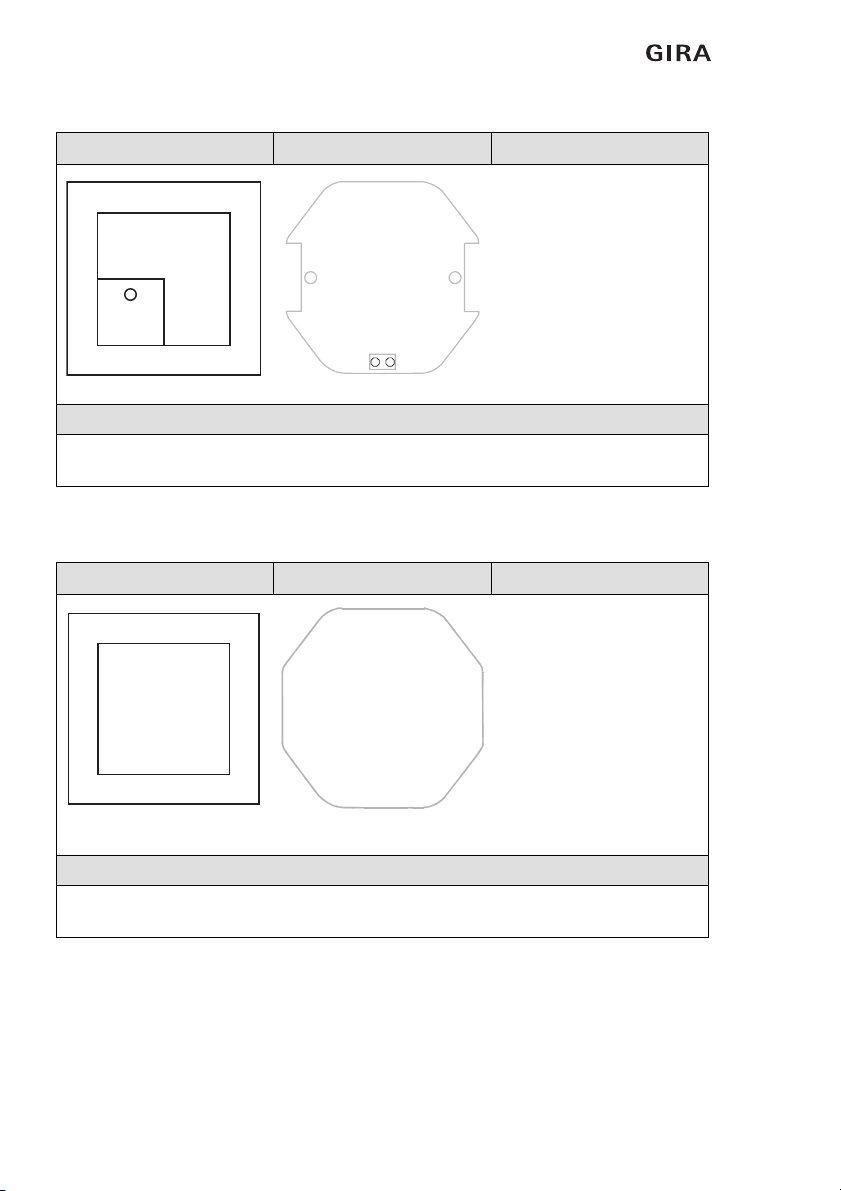
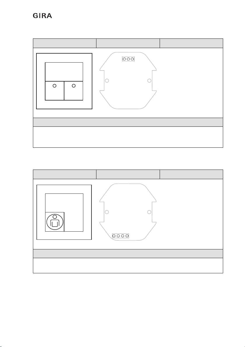
1.2 Scope of delivery ............................................................................................ 5
1.3 Area of application ......................................................................................... 8
1.4 Interfaces and connection options ................................................................. 8
2. Installation and start-up ......................................................................... 9
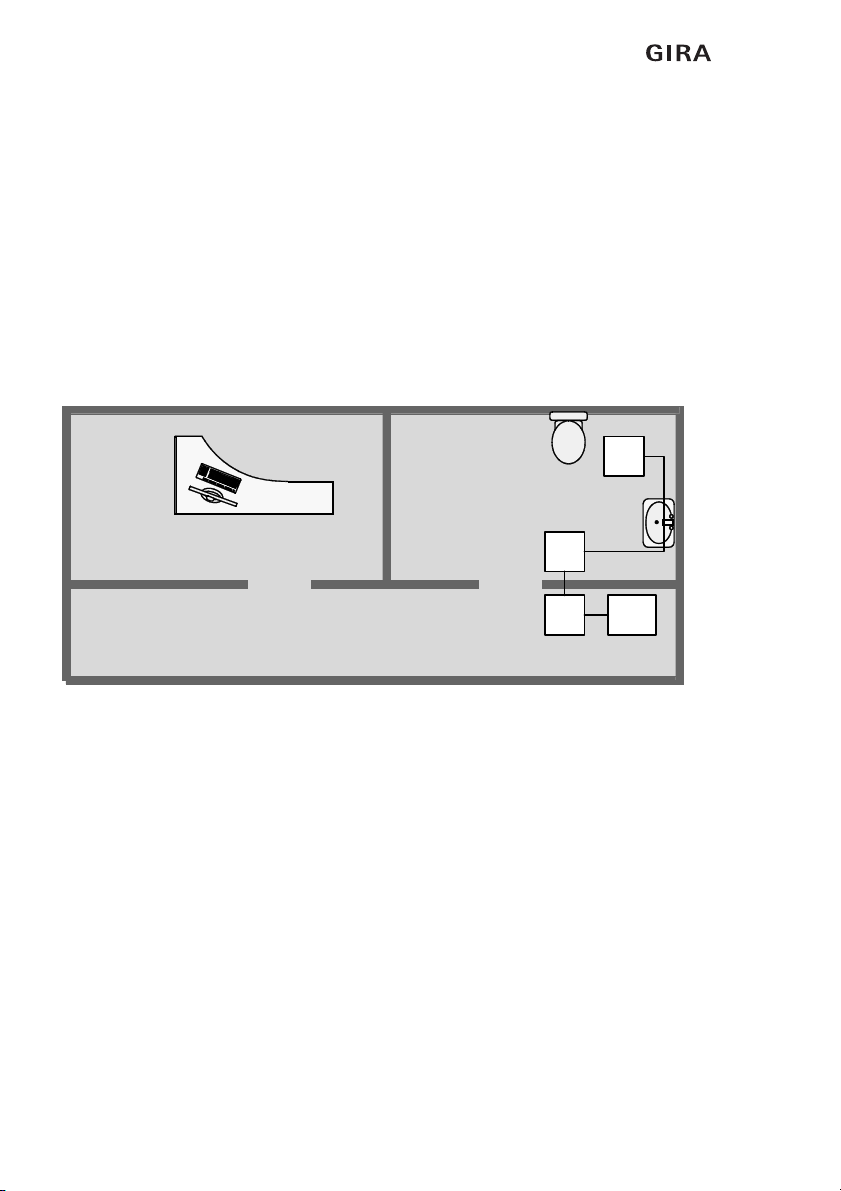
2.1 Recommended installation heights for devices ............................................. 9
2.2 Recommended installation height for the call module................................... 9
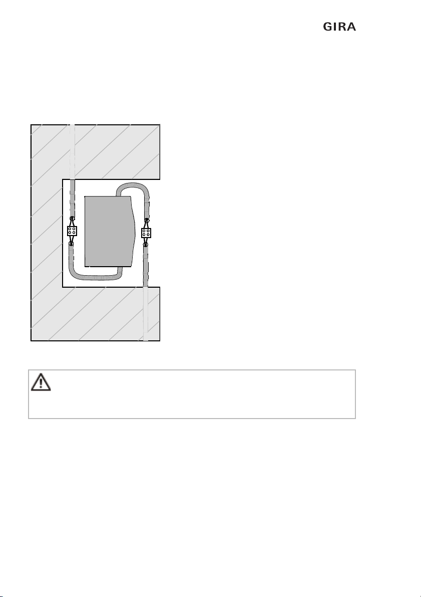
2.3 Installation of power supply unit .................................................................... 10
2.4 Functional description .................................................................................... 11
2.5 Wiring routing ................................................................................................ 11
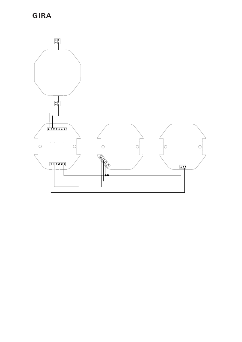
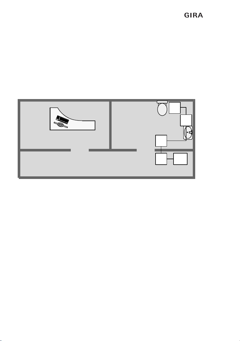
2.6 Emergency set standard system .................................................................... 12
2.6.1 Wiring of the call triggering components....................................................... 12
2.6.2 Wiring of the call switch-off components ...................................................... 13
2.6.3 Wiring of the standard system ....................................................................... 14
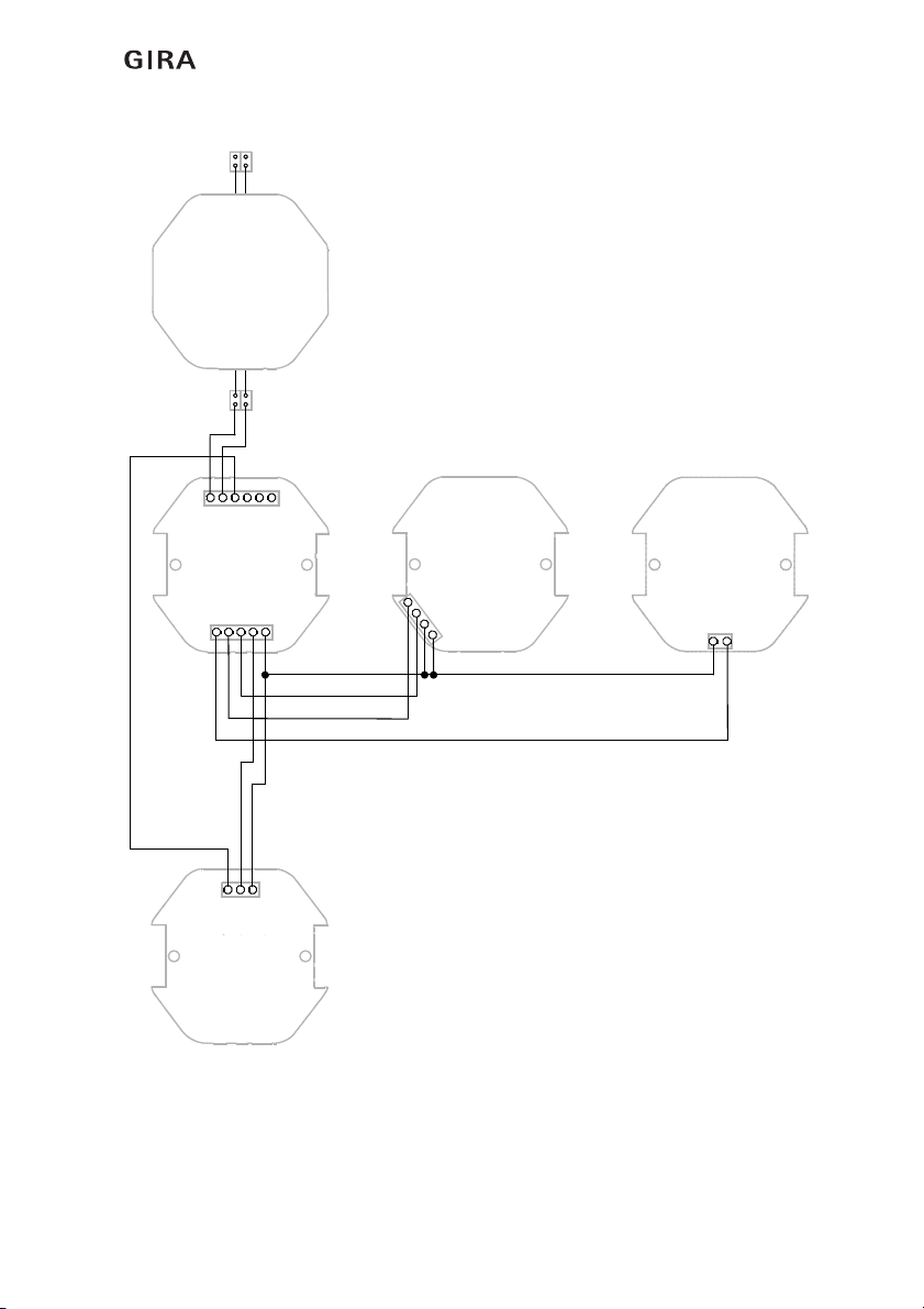
2.7 Expansion of Gira emergency set................................................................... 16
2.7.1 Expansion with a duty room unit ................................................................... 16
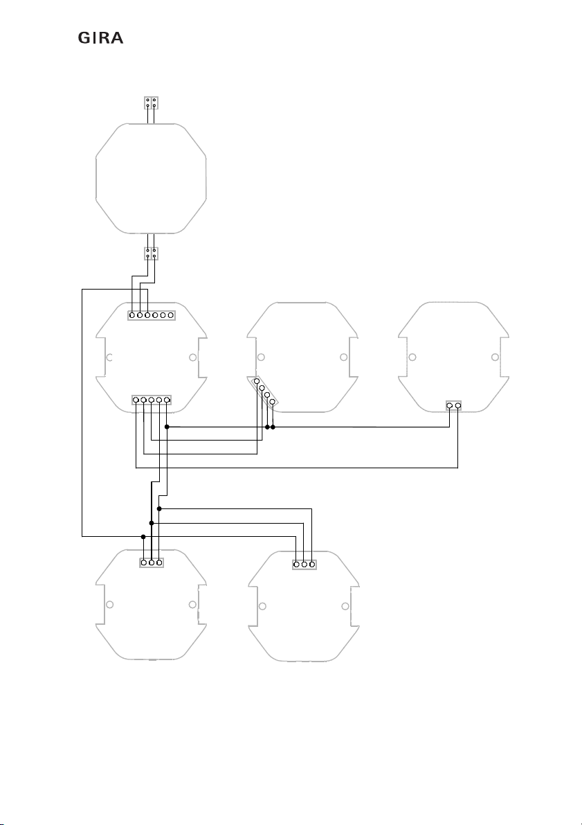
2.7.2 Expansion with two duty room units ............................................................. 18
2.7.3 Expansion with a call button .......................................................................... 20
2.8 The jumpers of the devices in the emergency set.......................................... 22
2.9 Call module..................................................................................................... 23
2.9.1 Relay contact for connection of an external device ....................................... 23
2.9.2 Linking of several call modules ...................................................................... 24
2.10 Starting up emergency set ............................................................................. 25
3. Operation ............................................................................................... 27
3.1 Call triggering ................................................................................................. 27
3.2 Call signalling ................................................................................................. 27
3.3 Switching call off............................................................................................ 27
3.4 Setting of acoustic signalling in the call module ............................................ 28
3.5 Connection of peripheral devices ................................................................... 28
3.6 Wire fracture................................................................................................... 28
3.7 Power failure .................................................................................................. 28
3.8 Maintenance and care .................................................................................... 28
4. Technical Data ....................................................................................... 29
4.1 Current consumption of components ............................................................ 30
5. Warranty ................................................................................................ 30

Introduction
411.2009/V 1.2
1. Introduction
The Gira emergency set is a wired call system and is suitable for example for installation in
WC's suitable for the handicapped.
1.1 General information
The technical data and specifications contained in these documents may be changed
without prior notification. The illustrations are also non-binding.
Subject to technical modifications!
No part of these documents may be duplicated or transmitted for any purposes, regardless
of the manner and means used (electronic or mechanical), without the expressed written
approval of Gira, Giersiepen GmbH & Co. KG.
All rights reserved.
© by Gira, Giersiepen GmbH & Co. KG
Dahlienstraße
D-42477 Radevormwald, Germany
i
Note: latest information is available on the Gira website.
As the device purchased by you is being constantly further developed and updated,
information in this manual may no longer be up-to-date.
The latest product information is available at the Gira website:
http://www.gira.de
Current documentation for your product is available at
http://www.download.gira.de

Introduction
5
11.2009/V 1.2
1.2 Scope of delivery
The following components are contained in the delivery scope of the emergency set
(order no. 2914 ..):
Call module, order number 2916 00 (abbreviation: RM)
Installation in flush-mounted box according to DIN 49073. Recommendation: deep box.
Pull-cord button, order number 2912 .. (abbreviation: ZT)
Installation in flush-mounted box according to DIN 49073.
Device view Connection assignment Legend
Contains both the electronics
for the emergency set as well
as the signal light.
+ 24 V Power supply
GND Earth
M Signal line to duty room
KW Base relay contact
KR Rest relay contact
KA Operating relay contact
+ 24 V_out Voltage (protected)
GND Earth (protected)
RT Call button
BL Reassurance light
AT Switch-off button
Function: call display.
Red signal light in the call module as flashing light with either pulsing buzzer tone see
"2.8 The jumpers of the devices in the emergency set" on page 22. Zero-voltage relay
contact for connecting for example a telephone dialler (not included in scope of delivery).
Signal light with continuous light and continuous buzzer tone signal a wire fracture. See
also "Call module" on page 23.
Device view Connection assignment Legend
Connection to: call module
RLWC Call light WC call
RTWC\ Call button WC call (Out)
RTWC Call button WC call (In)
+ 24 V Power supply
Function: call triggering.
Pull cord with red handle on pull-cord button. Red reassurance light lights up in the
housing of the pull-cord button. Red signal light in the call module lights up. Also buzzer
may tone.
+24V
GND
M
KW
KR
KA
AT
BL
RT
GND
+24V_out
PCB
Back
RLWC
RTWC\
RTWC
+24 V
PCB
Back

Introduction
611.2009/V 1.2
Switch-off button, order number 2911 .. (abbreviation: AT)
Installation in flush-mounted box according to DIN 49073.
Power supply unit 24 V/250 mA, order number 2969 .., (abbreviation: NNRS)
Installation in flush-mounted box according to DIN 49073. Recommendation: deep box.
Device view Connection assignment Legend
Connection to: call module
+ 24 V Power supply
AT Switch-off button
Function: call switch-off.
Press green switch-off button. Red signal light in the call module goes out, buzzer
tone is muted.
Device view
Power supply unit for flush-
mounted installation
Function: power supply of emergency set.
230 V/24 V, 250 mA. The power supply unit can be loosely placed into a flush-mounted
box.
+24 V
AT
PCB
Back
230V~
24VDC

Introduction
7
11.2009/V 1.2
Optional: duty room unit, order number 2915 .. (abbreviation: DZ)
Installation in flush-mounted box according to DIN 49073.
Optional: call button, order number 2900 .. (abbreviation: (RT)
Installation in flush-mounted box according to DIN 49073.
Device view Connection assignment Legend
Connection to: call module
M Signal line to duty room
GND Earth
+ 24 V Power supply
Function: reception unit for calls in emergency set, suppression of buzzer tone.
Mark presence with green button (a buzzer tone in an emergency only tones with set
presence). The yellow button has a red LED (call lamp) that lights up if a call was
triggered. With the yellow button the buzzer tone is suppressed for 20 seconds.
Device view Connection assignment Legend
Connection to: call module
+ 24 V Power supply
RT Call button (In)
RT\ Call button (Out)
RL Call light
Function: call triggering.
Trigger call with red button. Red reassurance light lights up in the call button. Red signal
light in the call module lights up. Also buzzer may tone.
M
GND
+24 V
PCB
Back
+24 V
RT
RT\
RL
PCB
Back

Introduction
811.2009/V 1.2
1.3 Area of application
The Gira emergency set is used to signal emergency situations and for alarming personnel.
Signalling of an emergency situation is via a red signal light in the call module as well as
acoustically via a buzzer (activated optionally) in the call module.
An additional call button and duty room unit can be optionally connected to the emergency
set as a reception unit via which a call can be signalled visually and acoustically, e.g. in
another room.
The Gira emergency set is suited to all areas of application in which the installation of a call
system according to DIN VDE 0834 is not expressly required, but where use of a call system
is still expedient and is also thoroughly recommended due to high risk factors. Thus
installation is possible in locations such as public outdoor facilities (e.g. toilet rooms in public
baths), in public buildings such as administrative authorities, museums, department stores
and also at places of work with especially high risk potential.
The range of application therefore covers for example all rooms in which persons who are
alone (without visual or acoustic contact to their surroundings) may become subject to an
emergency situation.
Gira assumes neither legal responsibility nor provides a guarantee for errors and damage of
any kind as a result of improper use and/or unprofessional installation of the emergency set.
1.4 Interfaces and connection options
The emergency set features the following interfaces and connection options:
– Relay contact (zero-voltage connection) in the call module, for connection of an
external device (e.g. Gira TeleCoppler, order number 0363 00). See also "Call
module" on page 23.
Consult the operating instructions of the external device!

Installation and start-up
9
11.2009/V 1.2
2. Installation and start-up
Installation of the Gira nurse call system is to be carried out by a skilled electrician only. He
must pay attention to the applicable requirements of DIN VDE 0834, DIN VDE 0100 and
further standards as well as statutory regulations.
All emergency set devices are installed in flush-mounted boxes.
Wiring may be carried out with cable material such as J-Y(St)Y, 4 x 2 x 0.6 mm. When
selecting cable material, further regulations and directives (e.g. freedom from halogen)
must be observed.
2.1 Recommended installation heights for devices
Devices such as the call button or switch-off button should be mounted to a height of
0.7 m to 1.5 m. DIN 18024-2 (barrier-free construction) also stipulates that operating
elements for wheelchair patients should be mounted to a height of 0.85 m. With pull-
cord buttons in bathroom units, specific requirements specified by DIN 0100-710 must
be adhered to. Pull-cord buttons must be fitted at least 20 cm above the highest
possible position of the shower head. It must be possible for the pull cord to be reached
by persons lying on the floor.
2.2 Recommended installation height for the call module
The call module should be mounted to a height of 1.5 m to 2.2 m.
i
Note: reef knot on handle of pull-cord button.
The handle of the pull-cord button is to be secured with a reef knot on the pull cord.

Installation and start-up
10 11.2009/V 1.2
2.3 Installation of power supply unit
Care must be taken that the 230 V~ cable remains separate from the 24 V cable during
installation.
We recommend: positioning the power supply unit to partition the cables.
Figure 2.1: Separation of the power supply areas with the power supply unit
Important! Ensure uninterruptible power supply!
It is recommended to use an uninterruptible power supply (UPS) in order to ensure
continued functionality of the emergency set in case of power failure.
230 V ~
24 V
Netzteil
UP 250 mA
(NNRS)
24 V
Power supply
unit,
flush-mounted
250 mA
230 V

Installation and start-up
11
11.2009/V 1.2
2.4 Functional description
If a person in need of help pulls on the cord of the pull-cord button (optional: pressing the
red button on the call button), a call is triggered. The triggered call is signalled by a
reassurance light in the housing of the pull-cord button. Simultaneously the red signal light
of the call module located outside of the room signals that help is needed in the room.
The optional duty room unit can be installed for example at a central point e.g. in the
doorman's room. This visually signals the call to the personnel by lighting up of a call lamp
in the button of the unit and also acoustically with a buzzer tone. The call can be
acknowledged with the "buzzer OFF" button (yellow): the acoustic signal is suppressed for
approx. 20 seconds.
The switch-off button is located in the room where the call was triggered and is installed
adjacent to the door. A triggered call can be deactivated by the person hurrying to give help
pressing the green switch-off button.
Visual call signalling is with a flashing light.
The acoustic call signalling can be optionally connected directly in the call module via a
jumper on the call module (see "The jumpers of the devices in the emergency set" on
page 22).
The call module features a zero-voltage relay contact. This can be used for example for
connection of a Gira TeleCoppler (optional). See also "Call module" on page 23.
The call triggering components are monitored for wire fracture. In cases of wire fracture the
red signal light lights continuously. If the jumper is connected to the call module a
continuous acoustic signal is emitted with wire fracture.
Following power failure a triggered call is retained.
The maximum distance between call module and duty room unit (reception unit) is 500 m.
2.5 Wiring routing
With wiring routing the following factors are important, partly also specified by
DIN VDE 0834:
- Fireproof routing in escape routes.
- Safe electrical isolation from high voltage systems.
- Prevention of malfunctions by other systems.
- Safe wire connection.
Many federal states stipulate halogen-free installation material (including cabling and flush-
mounted boxes) for public buildings. This requirement is also applicable for use of
supplementary mounting aids such as clamps.
Gira emergency set devices are equipped with screw terminals.

Installation and start-up
12 11.2009/V 1.2
2.6 Emergency set standard system
As standard, the call triggering components of the Gira emergency set are wired according
to the so-called idle current principle (series connection). Wiring of the call switch-off
components is carried out according to the working current principle (parallel connection).
2.6.1 Wiring of the call triggering components
The call triggering components, e.g. pull-cord buttons and call buttons are connected in
series (idle current principle). If the call system is in idle state, a low current flows (idle
current). When the corresponding button is pressed the flow of current is interrupted, thus
triggering the call.
Figure 2.2: Wiring example for call triggering components (idle current principle)
+24V
RT
RT\
RL
Optional:
Ruftaster (RT)
RL
WC
RTWC\
RTWC
+24V
Zugtaster
(ZT)
+24V
GND
M
KW
KR
KA
AT
BL
RT
GND
+24V_out
Rufmodul
(RM)
Netzteil UP 250 mA
(NNRS)
GND
+24 V
RT
+24 V_out
BL
RTWC\
+24 V
RLWC
RTWC RT\ RT
+24 V
RL
Rufmodul (RM) Zugtaster (ZT) Ruftaster (RT)
Call module (RM) Pull-cord button (ZT) Call button (RT)
Power supply unit,
flush-mounted
250 mA
(NNRS)
Call module
(RM)
Pull-cord button
(ZT)
Optional:
Call button
(RT)

Installation and start-up
13
11.2009/V 1.2
2.6.2 Wiring of the call switch-off components
The call switch-off components, e.g. switch-off button, are connected in parallel (working
current principle). If a call was triggered in the call system, pressing of the switch-off button
for example closes the circuit again, thus switching off the call.
Figure 2.3: Wiring example for call switch-off components (working current principle)
+24V
AT
Optional:
Abstelltaster
(AT)
+24V
AT
Abstelltaster
(AT)
+24V
GND
M
KW
KR
KA
AT
BL
RT
GND
+24V_out
Rufmodul
(RM)
Netzteil UP 250 mA
(NNRS)
AT AT
+24 V
Rufmodul (RM) Abstelltaster (AT)
GND
+24 V +24 V_out
AT
+24 V
Abstelltaster (AT)
Call module (RM) Switch-off button (AT) Switch-off button (AT)
Power supply unit,
flush-mounted
250 mA
(NNRS)
Call module
(RM)
Switch-off button
(AT)
Optional:
Switch-off button
(AT)

Installation and start-up
14 11.2009/V 1.2
2.6.3 Wiring of the standard system
A WC suitable for the handicapped with pull-cord button and switch-off button can be
equipped with the standard variant of the Gira emergency set. A call triggered by the pull-
cord button is visually signalled by the red signal light of the call module outside, adjacent
to the door of the WC. The call is switched off with the switch-off button in the WC area next
to the door when the danger situation has been dealt with.
Components used:
– Call module (RM)
– Pull-cord button (ZT)
– Switch-off button (AT)
– Power supply unit, flush-mounted, 250 mA (NNRS)
Figure 2.4: Example for emergency set in a WC suitable for the handicapped
A 4 x 2 x 0.6 mm cable must be laid for each emergency set component.
This method of cable routing guarantees sufficient numbers of wires even after
modifications to the system have been carried out.
We recommend: call module and power supply unit installation in a deep flush-mounted
box.
RM NNRS
AT
ZT

Installation and start-up
15
11.2009/V 1.2
Figure 2.5: Wiring of emergency set as standard variant
+24V
AT
Abstelltaster
(AT)
RLWC
RTWC\
RTWC
+24V
Zugtaster
(ZT)
+24V
GND
M
KW
KR
KA
AT
BL
RT
GND
+24V_out
Rufmodul
(RM)
230V~
24VDC
Netzteil 250 mA
(NNRS)
Call module
(RM)
Pull-Cord button
(ZT)
Switch-off button
(AT)
Power supply unit,
flush-mounted
250 mA
(NNRS)

Installation and start-up
16 11.2009/V 1.2
2.7 Expansion of Gira emergency set
Additional application possibilities become available with specific expansion of the Gira
emergency set with e.g. duty room units or call triggering components. The following shows
some examples for expansion of the emergency set.
2.7.1 Expansion with a duty room unit
With expansion of the emergency set with a duty room unit, a call from a WC suitable for
the handicapped for example can be signalled visually and acoustically in a room from which
the call module cannot be seen. Possible areas of application: medical and massage
practices, relaxation rooms, self-contained flats etc.
Components used:
– Emergency set, order number 2914 ..
– Additionally: duty room unit (DZ), order number 2915 ..
Figure 2.6: Example for expansion of the emergency set with a duty room unit
RM NNRS
AT
ZT
DZ

Installation and start-up
17
11.2009/V 1.2
Figure 2.7: Wiring with a duty room unit
+24V
AT
Abstelltaster
(AT)
RL
WC
RTWC\
RTWC
+24V
Zugtaster
(ZT)
M
GND
+24V
Optional:
Dienstzimmer-
einheit (DZ)
+24V
GND
M
KW
KR
KA
AT
BL
RT
GND
+24V_out
Rufmodul
(RM)
230V~
24VDC
Netzteil 250 mA
(NNRS)
Call module
(RM)
Pull-Cord button
(ZT)
Switch-off button
(AT)
Power supply unit,
flush-mounted
250 mA
(NNRS)
Optional:
duty room unit
(DZ)

Installation and start-up
18 11.2009/V 1.2
2.7.2 Expansion with two duty room units
With expansion of the emergency set with two duty room units, a call from a WC suitable
for the handicapped for example can be signalled visually and acoustically in two separate
rooms from which the call module cannot directly be seen. Possible areas of application:
medical and massage practices, relaxation rooms, self-contained flats etc.
Components used:
– Emergency set, order number 2914 ..
– Additionally: 2 x duty room unit (DZ), order number 2915 ..
Figure 2.8: Example for expansion of the emergency set with two duty room units
RM NNRS
AT
ZT
DZ DZ

Installation and start-up
19
11.2009/V 1.2
Figure 2.9: Wiring with two duty room units
+24V
AT
Abstelltaster
(AT)
RLWC
RTWC\
RTWC
+24V
Zugtaster
(ZT)
M
GND
+24V
Optional:
Dienstzimmer-
einheit (DZ)
M
GND
+24V
Optional:
Dienstzimmer-
einheit (DZ)
+24V
GND
M
KW
KR
KA
AT
BL
RT
GND
+24V_out
Rufmodul
(RM)
230V~
24VDC
Netzteil 250 mA
(NNRS)
Call module
(RM)
Pull-Cord button
(ZT)
Switch-off button
(AT)
Power supply unit,
flush-mounted
250 mA
(NNRS)
Optional:
duty room unit
(DZ)
Optional:
duty room unit
(DZ)

Installation and start-up
20 11.2009/V 1.2
2.7.3 Expansion with a call button
Expansion of the Gira emergency set with a call button can be used for example for call
triggering from a washbasin in a WC suitable for the handicapped. Wiring is in accordance
with the idle current principle (see "Wiring of the call triggering components" on page 12).
Possible areas of application: medical and massage practices, relaxation rooms, self-
contained flats etc.
Components used:
– Emergency set, order number 2914 ..
– Additionally: call button (RT), order number 2900 ..
Figure 2.10: Example for expansion of the emergency set with a call button
RM NNRS
AT
ZT
RT
Table of contents
Other Gira Industrial Electrical manuals