Gira KNX Series Operator's manual

KNX/EIB
Product documentation
Issue:
09.03.2011
Choke
Order-No. 0581 00
60050211

Order-No. 0581 00
Contents
1 Product definition 3 ................................................................................................................
1.1 Product catalogue 3 ...........................................................................................................
1.2 Function 3 ..........................................................................................................................
2 Installation, electrical connection and operation 4 .............................................................
2.1 Safety instructions 4 ..........................................................................................................
2.2 Device components 5 ........................................................................................................
2.3 Fitting and electrical connection 6 .....................................................................................
2.4 Commissioning 8 ...............................................................................................................
3 Technical data 9 ......................................................................................................................
4 Scope of functions 10 .............................................................................................................
5 Appendix 11 .............................................................................................................................
5.1 Index 11 .............................................................................................................................
KNX/EIB
Product documentation
Page 2 of 12

Order-No. 0581 00
1 Product definition
1.1 Product catalogue
Product name: Choke
Use: System device
Design: Rail-mounted device
Order-No. 0581 00
1.2 Function
The KNX choke is a system component. It decouples a KNX line from the respective KNX
power supply and thus prevents the short-circuit of the data telegrams by the power supply unit.
The choke additionally forms the line terminator required for function-oriented signal
transmission.
If an unchoked voltage output of a KNX power supply is used, the KNX choke can be used to
supply another KNX line.
Page 3 of 12
Product definition
Order-No. 0581 00
2 Installation, electrical connection and operation
2.1 Safety instructions
Electrical equipment may only be installed and fitted by electrically skilled persons. The
applicable accident prevention regulations must be observed.
Failure to observe the instructions may cause damage to the device and result in fire and
other hazards.
Hazard due to electric shock on all parts of the bus installation. During assembly with
data rail, cover free areas of the data rai with cover strips.
The device may not be opened or operated outside the technical specifications.
Page 4 of 12
Installation, electrical connection and operation

Order-No. 0581 00
2.2 Device components
Figure 1: Device components
(1) Bus connection
(2) Connection DC 30 V
(3) Reset LED (red)
On: Bus line is short-circuited, bus reset.
(4) Reset switch for bus line
Position ON: Bus line in operation
Position Reset: Bus line is short-circuited, bus reset.
i A bus reset should take at least 20 seconds.
Page 5 of 12
Installation, electrical connection and operation
Order-No. 0581 00
2.3 Fitting and electrical connection
DANGER!
Electrical shock when live parts are touched.
Electrical shocks can be fatal.
Before working on the device, disconnect the power supply and cover up live
parts in the working environment.
Fitting and connecting device with data rail
If a data rail is used, bus line and power supply DC 30 V can be supplied to the device via data
rail contacts.
The connection of additional cables to the device via terminals is optional if the bus line and
power supply are already connected to the data rail via additional data rail connectors. In this
case, the terminals of the device can be used as additional data rail connectors to connect an
outgoing bus cable, for example.
If no data rail connectors are used, bus line and power supply DC 30 V must be connected to
the device via terminals. The data rail will then be supplied via the device.
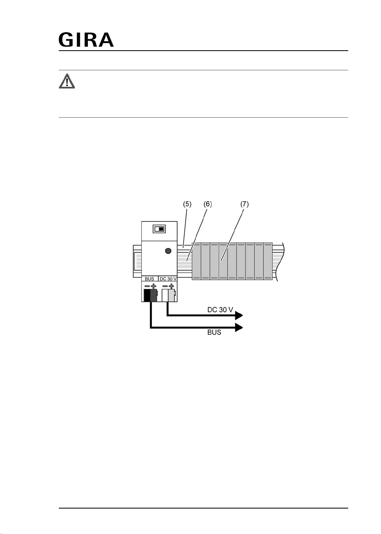
Figure 2: Device connection with data rail
Data rail (6) is glued into mounting rail (5).
o Snap device onto DIN rail.
o Cover free areas of the data rail with cover strips (7).
Optional, if additional data rail connectors are available:
o Connect power supply to the terminal (2) (Figure 1).
o Connect bus line to terminal (1).
Fitting and connecting device without data rail
The device can be used without data rail. Bus line and power supply DC 30 V must be
connected to the device via terminals.
Page 6 of 12
Installation, electrical connection and operation

Order-No. 0581 00
Figure 3: Rear view of device
o Remove the guide (8) of the data rail contacts. To do this, insert a small screwdriver
laterally between the housing and guide and raise the guide.
o Attach the enclosed insulating cap (9) onto the data rail contacts and lock into place by
pressing.
o Snap device onto DIN rail.
o Connect power supply to the terminal (2) (Figure 1).
o Connect bus line to terminal (1).
Page 7 of 12
Installation, electrical connection and operation

Order-No. 0581 00
2.4 Commissioning
After properly fitting, the device is ready for operation. The device has no physical address and
no application program either. Consequently, commissioning by the ETS is not necessary.
i A KNX choke can generally be added to an ETS project in order to create parts lists or to
test projects successfully, for example. A product entry is available in the manufacturer's
catalogue (without application program) for the KNX choke whereby the device is
integrated into a line or area and thus the ETS project can be completed.
Page 8 of 12
Installation, electrical connection and operation

Order-No. 0581 00
3 Technical data
General
Mark of approval KNX/EIB
Ambient temperature -5 ... +45 °C
Storage/transport temperature -25 ... +70 °C
Relative humidity 5 ... 93 % (No moisture condensation)
Fitting width 36 mm / 2 modules
Weight approx. 100 g
Connection KNX "Bus"
KNX medium TP 1
Bus output voltage DC 28 ... 31 V SELV
Output current 640 mA (all outputs)
Connection, Bus Connection terminal
Connection "DC 30 V"
Rated voltage DC 29 ... 32 V SELV
Connection of power supply Connection terminal
Page 9 of 12
Technical data

Order-No. 0581 00
4 Scope of functions
- Decoupling of bus line and power supply.
- Operation with or without KNX data rail possible.
- Contact to the data rail via contact spring system.
- Terminals on the panel of the device for bus terminal and power supply.
- Reset switch for activation of the bus line.
- Indicator LED for reset state.
Page 10 of 12
Technical data

5 Appendix
5.1 Index
A
application program .. ............................. 8
C
commissioning .. ..................................... 8
D
data rail .. ................................................ 6
data rail connectors .. ............................. 6
data rail contacts .. ................................. 6-7
E
ETS .. ................................................... 8
I
insulating cap .. ....................................... 7
Order-No. 0581 00 Page 11 of 12
Appendix

Order-No. 0581 00
Gira
Giersiepen GmbH & Co. KG
Elektro-Installations-
Systeme
Industriegebiet Mermbach
Dahlienstraße
42477 Radevormwald
Postfach 12 20
42461 Radevormwald
Deutschland
Tel +49(0)21 95 - 602-0
Fax +49(0)21 95 - 602-399
www.gira.de
Page 12 of 12
Appendix
This manual suits for next models
1
Table of contents
Other Gira Industrial Electrical manuals


