Gira Energy Profile1347 26/27/28 User manual

Installation and
operating manual
Energy Profile
1341 26/27/28
1347 26/27/28
Energy Profile with lighting element
1342 26/27/28
1348 26/27/28
Light Profile
1343 26/27/28
Light Profile, small
1344 26/27/28


3
Table of Contents
Description........................................................ 5
Construction ..................................................... 5
Energy Profile installation ................................. 6
Connecting the wiring....................................... 7
Installing and replacing lamps .......................... 8
Installation of slats element .............................. 8
Empty connection units .................................... 9
Specifications.................................................. 10
Manufacturer's warranty................................. 10

5
Description
The Energy Profile is made from painted alumin-
ium and designed for outdoor use in domestic
applications to provide electrical power and area
or orientation lighting.
Various types of connectors and switches can
also be integrated into Energy Profiles, such as
telephone and loudspeaker sockets or light
switches.
Gira Energy Profiles are available in four different
models in the colours pure white, anthracite grey
and aluminium:
• Energy Profile
with three SCHUKO socket outlets
Order no. 1341 26/27/28
with three socket outlets with earthing pin
Order no. 1347 26/27/28
• Energy Profile with a lighting element
with empty unit and
two SCHUKO socket outlets
Order no. 1342 26/27/28
with empty unit and
two socket outlets with earthing pin
Order no. 1348 26/27/28
• Light Profile (height: 769 mm)
Order no. 1343 26/27/28
• Small Light Profile (height: 491 mm)
Order no. 1344 26/27/28
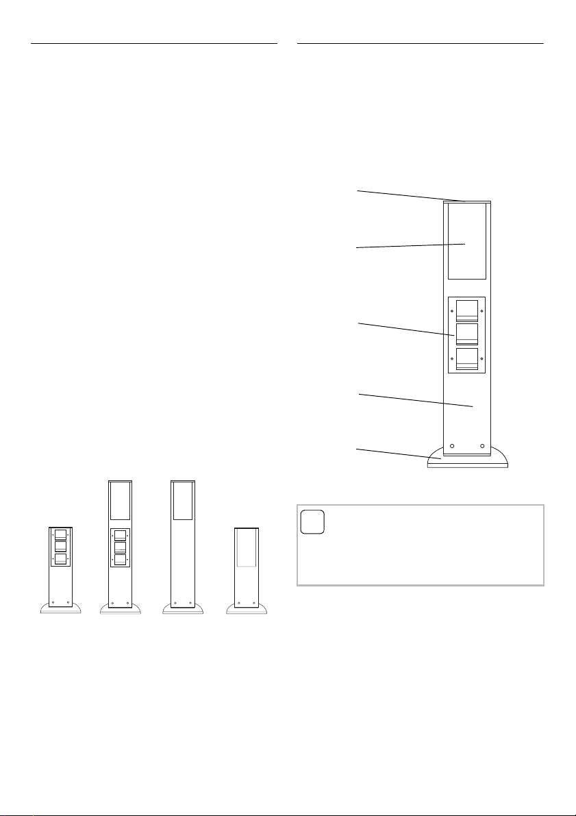
Construction
The basic construction of an Energy Profile with
lighting element is illustrated here:
(1) top cover
(2) lighting element with light panel
(3) connection unit with TX_44 switch plate
(4) profile
(5) profile base
i
Maintenance instructions
Please clean your Energy Profile using only
soapy water or a solvent-free, non-foaming
cleaning agent.
1
2
3
4
5

6
Energy Profile installation
The Energy Profile can be fitted with just one
screw. Depending on the conditions of the under-
lying surface, there are two different options for
anchoring the Energy Profile to the ground.
Using a soil tube
On loose or soft subsoil, such as a flower bed or
lawn, install the Energy Profile using a soil tube.
Please proceed as follows:
1. Dig a hole (of approximately 50 cm) at the
location where you wish to install the profile.
2. Feed the lead-in cables (i.e. power cables and
telephone or loudspeaker cables) through the
tube.
3. Fill the excavated hole with concrete and place
the tube upright in the hole.
4. Feed the lead-in cables through the profile
base.
5. Fasten the profile base to the tube using the
provided hexalon-head screw.
6. Connect the Energy Profile wiring (see
page 7).
7. Connect the earth lead of the Energy Profile to
the earth terminal on the profile base.
8. Place the Energy Profile on the profile base
and fasten it in place using the three Allen
screws.
i
Condensation opening
Before installing the Energy Profile, open the
condensation exit on the bottom of the profile
base. To do so, break out the tab for the opening
and remove any rough edges using a file.
Positioning the soil tube
When cementing the soil tube in place, bear in
mind the desired position of the Energy Profile.
The Energy Profile can be rotated around the
axis of the soil tube by up to 20 degrees to adjust
its orientation.

7
Direct screw fitting
On a firm underlying surface, such as brick, con-
crete or asphalt, the Energy Profile can be
installed directly on the ground.
Please proceed as follows:
1. Drill a hole where you want to install the pro-
file and insert the supplied plug.
2. Feed the lead-in cables (mains power cable
and telephone or loudspeaker cable, if applica-
ble) through the profile base.
3. Fasten the profile base to the ground using the
provided hexagon-head screw.
4. Connect the Energy Profile (see page 7).
5. Connect the earth wire of the Energy Profile to
the earth terminal on the profile base.
6. Place the Energy Profile on the profile base
and fasten it using the three Allen screws.
Connecting the wiring
The Energy Profile's lighting element and socket
outlets are pre-wired up to the connection termi-
nals.
Proceed as follows to connect the Energy Profile
to the mains circuit:
1. Remove the terminal box from the bottom
opening of the Energy Profile and open it.
2. The connection of the terminals depends on
the Energy Profile model.
For Energy Profiles with connection unit, con-
nect the power cable for the socket outlets to
the L/N/ terminals.
For Energy Profiles with a lighting element,
the lighting is connected via the /N/ termi-
nals.
3. The free and unlabeled terminals can be used
for wiring the empty unit.
4. Close the terminal box and slide it back into
the Energy Profile.
5. Connect the Energy Profile earth lead to the
earth terminal on the profile base.
Note!
The installation and assembly of electrical equip-
ment may only be performed by a qualified elec-
trician.
LN
8
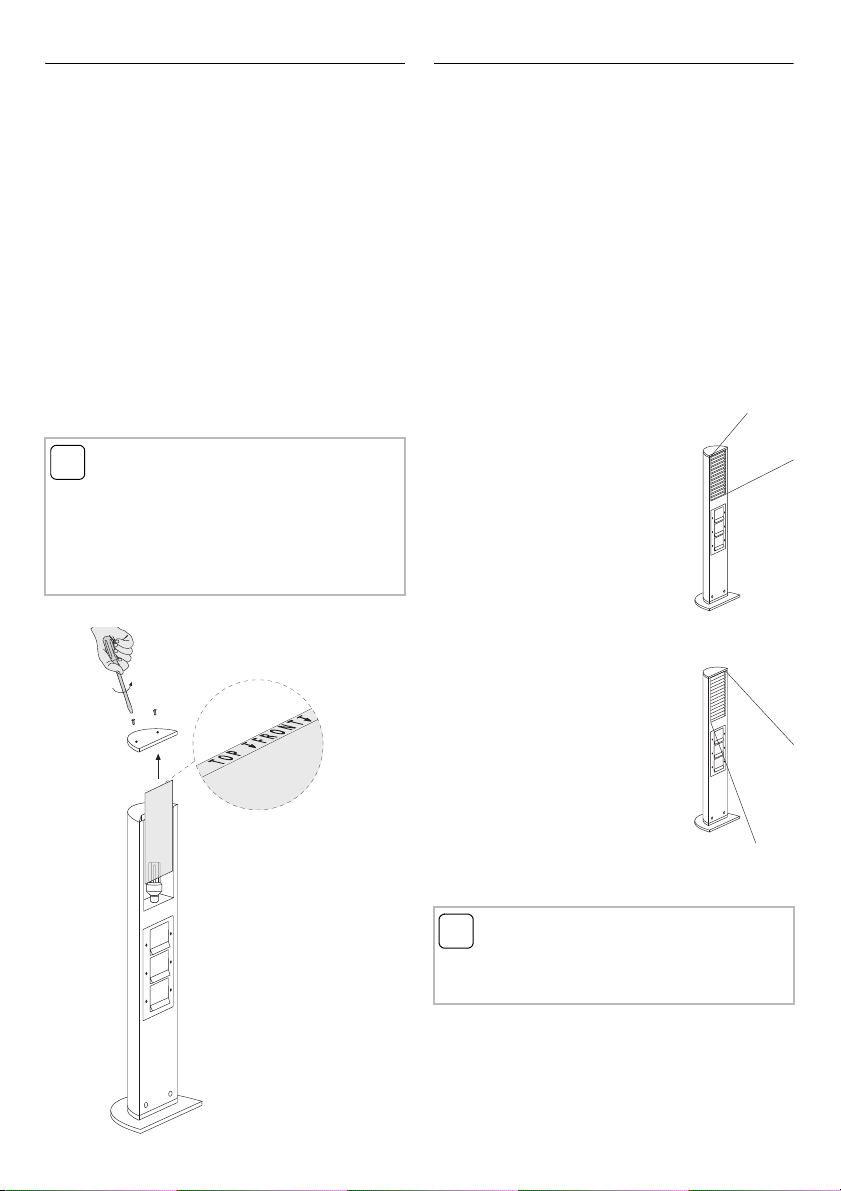
Installing and replacing lamps
A Compact fluorescent lamp with E27 socket is
used in the Energy Profile as a light source. More
information about suitable lamps can be found in
the Specifications on page 10.
In order to install or replace the lamp, please pro-
ceed as follows:
1. Remove the screws from the top cover and
remove the top cover from the profile.
2. Pull the light panel upwards, sliding it out of
the profile.
3. Place the lamp in the fitting.
4. Place the light panel by sliding it in the profile
from the top (pay attention to 'TOP FRONT'
indication).
5. Place the top cover and fasten with the
screws.
Installation of slats element
An optional slats element can be used in order to
focus the Energy Profile lighting element on
objects or paths.
To fit the slats element and the accompanying
transparent light panel, please proceed as fol-
lows:
1. Remove the screws from the top cover and
remove the top cover from the profile.
2. Pull the light panel upwards, sliding it out of
the profile.
3. Place the transparent panel by sliding it in the
profile from the top (pay attention to the 'TOP
FRONT' indication).
4. Fit the slats element:
with the slats directed upward
for object lighting, for example.
with the slats directed downward
for path lighting, for example.
5. Place the top cover and fasten it with the
screws.
i
Lamp diameter
Compact fluorescent lamps with a base diame-
ter of up to 52 mm can be used in the Energy
Profile.
If a slats element is used, the maximum base
diameter is reduced to 48 mm!
i
Transparent panel / light panel
The slats element can be used with either a
transparent panel or a satinised light panel.

9
Empty connection units
Energy Profiles with lighting elements have one
empty unit that can be individually fitted. This
empty unit is provided with an intermediate plate
and spring cover suitable for integrating System
55 base elements.
Please proceed as follows to fit a new base ele-
ment:
1. Remove the Torx screws securing the three-
fold switch plate and remove the switch plate
by inserting the tip of a screwdriver under the
lower corner and levering up the switch plate.
2. Remove the intermediate plate with spring
cover.
3. Using a screwdriver, prise the blind panel free
of the empty unit. Remove the screws from
the wall socket's base elements and remove
the base elements.
4. Remove the frame base.
5. Replace the blind panel supporting ring with a
new built-in base element.
6. Position the frame base.
7. Install the base elements and tighten with
screws if necessary.
8. Fit the intermediate plates with spring cover.
9. Click the switch plate firmly into place and
insert he Torx screws.
i
Integration of System 55 base ele-
ments
Certain System 55 base elements require a dif-
ferent intermediate plate and spring cover from
the TX_44 range. An overview of which base ele-
ments can be combined with which intermedi-
ate plates is provided in the Gira catalogue.
1.
2.
3.

10
Specifications
Dimensions (W x H x D):
Profile base: 229 x 10 x 155 mm
Small profile: 142 x 491 x 75 mm
Large profile: 142 x 769 x 75 mm
Protection: IP 44 with covers closed
Connections: Screw clamps, 1 x 4 mm2
or 2 x 2.5 mm2
Lamp: Compact fluorescent lamp with
E27 socket
Power: 21 W max.
Socket diameter: 52 mm max.
48 mm max. (if slats element
is used)
Lighting range
Large Light Profile, satinised light panel,
20 W lamp
Hight of point of light above ground: 0,65 m
Small Light Profile, satinised light panel,
20 W lamp
Hight of point of light above ground: 0,363 m
Manufacturer's warranty
We grant the guarantee on our units - irrespective
of claims arising out of the sales contract
between the final consumer and the vendor - as
follows:
1. Our warranty is limited at our discretion to
repair or replacement if the functioning is
impaired or not ensured due to proven defects
resulting from faults in material or workman-
ship.
2. The period of guarantee is governed by our
General Conditions of Sale. Adherence to this
period must be justified by confirmation of
purchase date in the form of invoice, delivery
note or similar documents.
3. The costs of transport are borne in all cases by
the purchaser.
Please return the unit postage paid to our central
service department giving a brief description of
the fault:
Gira
Giersiepen GmbH & Co. KG
Service Center
Dahlienstrasse 12
D-42477 Radevormwald
Federal Republic of Germany
The CE sign is a free trade sign
addressed exclusively to the authorities
and does not include any warranty of
any properties.
i
Caution: switch-on peak current
When using observers or Automatic switches,
please remember that compact fluorescent
lamps have relatively high switch-on peak cur-
rents.


Gira
Giersiepen GmbH & Co. KG
P.O. Box 1220
42461 Radevormwald
Germany
Telephone: ++49 / 2195 / 602 - 0
Telefax: ++49 / 2195 / 602 - 339
Internet: www.gira.de
E-Mail: [email protected]
10866537 43/18
This manual suits for next models
5
Table of contents
Popular Portable Generator manuals by other brands

Peak Scientific
Peak Scientific FUSION 1010 installation guide

Craftsman
Craftsman 919.670070 owner's manual

Troy-Bilt
Troy-Bilt 1925 owner's manual

Agilent Technologies
Agilent Technologies HP 83711A user guide

Anritsu
Anritsu MG3702xA Series Operation manual

Cromtech
Cromtech TG40RP Operation & instruction manual

WILDCAT POWER GEN
WILDCAT POWER GEN FR0131240NG-LPG Installation and operator's manual

Kubota
Kubota GL6000-STD Operator's manual

Olympus
Olympus USG-400 troubleshooting guide

GTS
GTS DGG Series Installation and operating manual

Predator
Predator 57480 user manual

Robust
Robust RB-PG 850 Original operating instructions


