Girard Systems NEWMAR SERVICE SCHOOL User manual

NEWMAR SERVICE SCHOOL
TRAINING INFORMATION GUIDELINE FOR FEBRUARY
2013

2 | P a g e
OUR PRODUCTS:
NOVA – DUAL PITCH AWNING
G-2000/ G-1500

3 | P a g e
G-2085
G-5000

4 | P a g e
G-LINKS

5 | P a g e
NOVA/ G-2000/ G-1500 – BASIC ADJUSTMENTS
A. ADJUSTING MOTOR LIMIT SWITCHES
NOTE: The motor limit switches have been adjusted to the correct position at the
factory prior to shipment. The awning motor is set to stop the exact moment the
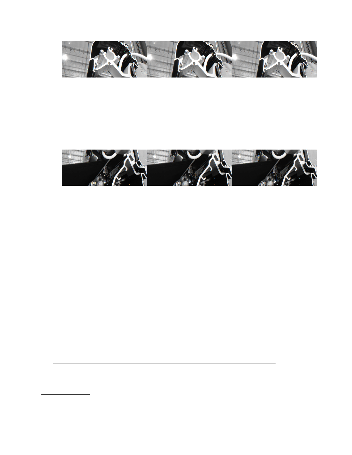
awning box closes. The fabric should be taut, the arms should be slightly bent,
exposing a 1/4” gap at the elbows.
Always check the motor limits after installation to ensure that the awning opens
and closes correctly. Awning fabric can stretch over time, this will require an
adjustment of the OUT limit switch.
IMPORTANT: EXTREME CARE SHOULD BE TAKEN TO ENSURE THAT THE MOTOR LIMIT
TURNS OFF AT THE EXACT MOMENT THE AWNING BOX CLOSES. FAILURE TO DO SO
WILL CAUSE THE MOTOR TO RUN WHEN THE AWNING IS CLOSED. THIS CAN
SUBSTANTIALLY REDUCE THE LIFE OF THE MOTOR.
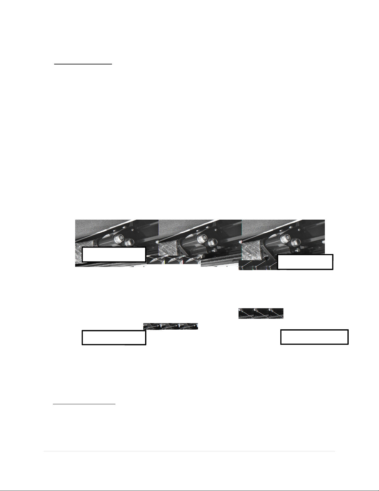
1. The AC motors used in Girard Systems awnings are reversible. Any
reference made to the motor limit switches in these instructions are based
on the right-hand placement of the motor. For left hand placement,
simply reverse the instructions. (Figure 8)
2. The motor has limit settings for both OUT (extension) and IN (retraction).
3. Adjust the limit switches with the black key provided with the awning, or
you may use a 4mm (5/32”) allen wrench.
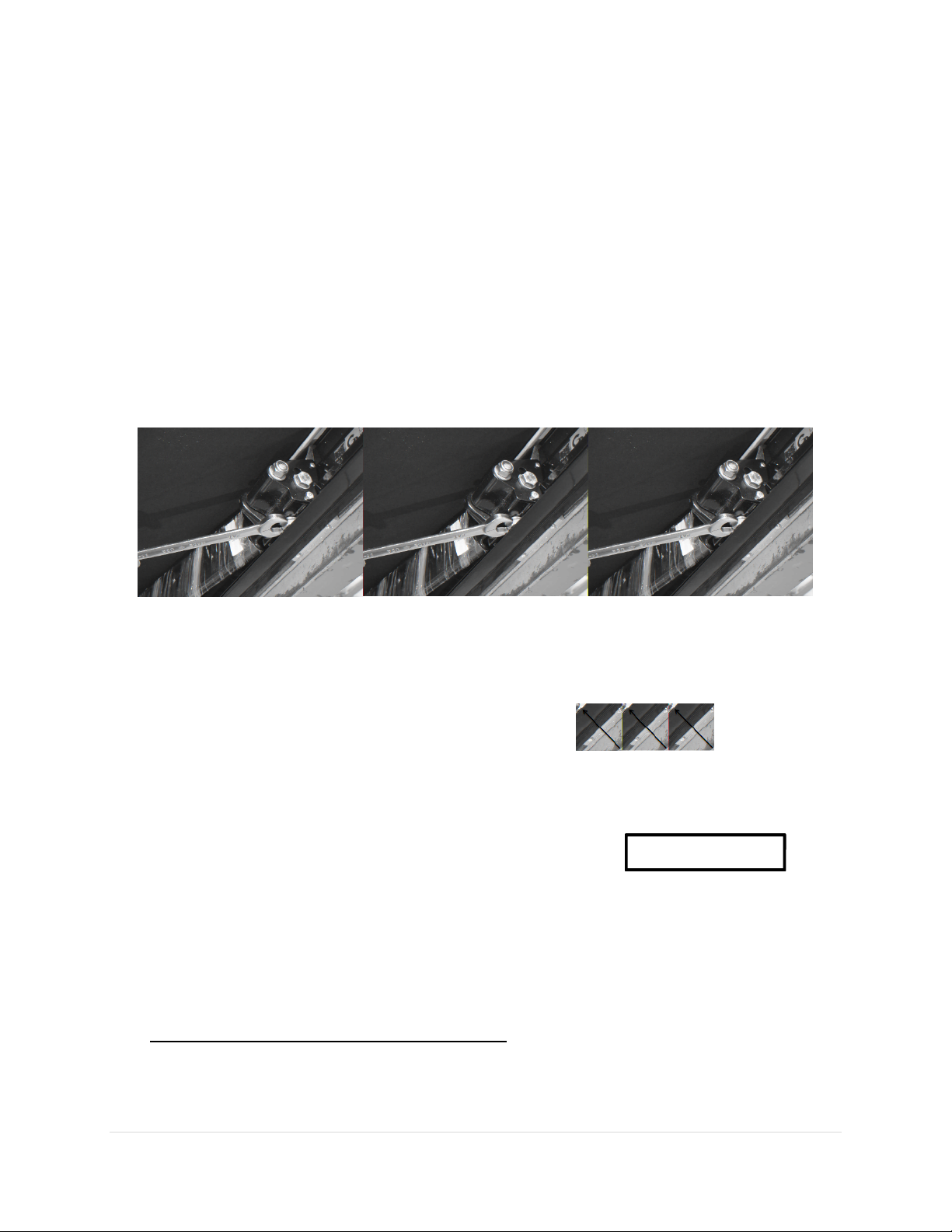
4. Extend the awning a few feet to gain access to the motor. Locate the
motor (standard installation is on the right hand side of the awning). The
limit adjustment holes are located on the head of the motor. Using the
symbols printed next to the adjustment holes, turn the black key (or 4mm
allen wrench) to make the necessary adjustments. Typically, the motors
are labeled with a (+) or a (-). (Figure 9)

6 | P a g e
1. (Figure 9)
5. Approximately ¼ turn of the adjustment screws represents about 1” of
awning movement. NEVER set outward limits so that the fabric is slack with
full arm extension. For proper adjustment set limit switch to stop the motor
just before the arms lock. This will expose about an 1/4” gap at the elbow.
B. ADJUSTING PITCH and ARM (Elbow) HEIGHTH
NOTE: This adjustment is usually required after an arm replacement. Also, when
the elbow of the arm hits the bottom of the casing as the lead rail closes.
Tools Required
19mm (3/4”) open-end wrench

7 | P a g e
10mm (3/8”) open-end wrench
A. ELBOW HEIGHTH
1. Extend the awning about 18”
2. On the selected arm, loosen the two(2) nylon nuts on the side of the
upper arm connection (shoulder), using a 19mm open-end wrench.
3. Locate the smaller adjustment bolt located directly below the rear lock
nut loosened in step #2. (Figure 10) Using a 10mm open-end wrench
rotate the bolt clockwise to TIGHTEN and raise the arm location inside the
cassette. Rotate the bolt counter-clockwise to LOOSEN or lower the arm
location inside the cassette.
4. NOTE: After retightening the nylon nuts, the arms will raise slightly higher.
5. Tighten the two(2) nylon nuts located on the side of the upper arm
connection.
6. Close the awning completely to ensure a proper fit.
(Figure 10)
B. ADJUSTING PITCH
NOTE: Your NOVA Awning will have the pitch adjusted to its highest point. DO
NOT TRY TO RAISE THE PITCH, this could result in damaging the awning.
1. Extend the awning about 18”.
Pivot bolt
Arm elevator screw
Adjustment bolt
Loosen
front bolt

8 | P a g e
2. On the arm selected, loosen the two(2) nylon nuts on the upper side of the
arm connection using a 19mm open-end wrench.
3. Locate the larger adjustment bolt located on the bottom of the upper
arm connection (shoulder). (Figure 11) Using a 19mm open-end wrench
rotate the bolt counter-clockwise to LOOSEN or lower the pitch. If the
pitch is lowered too far you may turn the bolt clockwise or TIGHTEN to raise
the pitch. DO NOT OVERTIGHTEN.
4. Tighten the two(2) nylon nuts located on the side of the upper arm
connection.
5. Close the awning completely to ensure a proper fit.
(Figure 11)
C. TESTING THE ANEMOMETER (Wind Sensor)
1. Partially extend the awning.
Adjustment bolt

9 | P a g e
2. Manually employ the anemometer by blowing on the cups or by spinning
them.
3. At this point the awning should retract; if not, check motor connection for
proper polarity.
NOTE: The Anemometer will send a retract signal to all of the awnings installed
on the RV. The power system of the vehicle must be able to withstand the
resulting surge of current. The surge will be the greatest when the awnings are
fully extended. When testing the system verify all of the awnings will close when
fully extended. If the system does not operate correctly under these conditions
you may:
A. Provide sufficient power from your panel.
B. Replace the anemometer in the electronics system with a Motion Sensor.
D. ADJUSTING THE LEAD RAIL
1. The lead rail on your awning has been preset from the factory at +/- 3
degrees. This allows the lead rail to rest firmly into the cassette and also creates
a weather resistant seal for travel. To increase or decrease the pitch angle insert
a 5mm allen wrench into the top pitch-angle screw. Turn clockwise to increase
the pitch and turn counterclockwise to decrease the pitch. (Figure 12)
(Figure 12)
Pitch
-
angle
screw
Horizontal lead rail
adjustment screw
Tension plate
Lead rail

10 | P a g e
G-5000 – BASIC ADJUSTMENTS
SPRING TENSION ADJUSTMENT
The tension of the Torsion Spring is preset at the factory between 7 and 8 full
turns.
1. To adjust the tension, facing the G5000, gently remove the left end (LH)
plastic cap.
2. Attach Girard Tension Tool to 3/8” rachet. Insert tension tool in to square
tube. Maintain tension on spring. Proceed to remove two center screws.
3. NOTE: Use caution when removing the two (2) center screws (#22) on the
slide plate: The spring is under tension and may cause the ratchet to turn
violently inflicting injury.
4. Hold the ratchet handle tight as you remove part the two center screws
from the spring support and carefully release all tension. Use channel locks
on the special tool to maintain the tension while repositioning the ratchet
handle.
5. Now you are ready for tensioning. Take up fabric slack. Apply 7 full turns,
or 14 half turns (follow arrows on end plate to tension).
6. Awnings of widths greater than 244 inches (G5000 Super-slide) are
equipped with two (2) springs (one at each end). In this case, you will also
need to adjust the tension of the second spring (right hand) (in this case
clockwise more tension, counter-clockwise less tension).
7. Replace the screws and plastic end cap.
SPRING REPLACEMENT
1. Facing the G5000, take care and remove the plastic end cap.
2. Attach Girard Tension Tool to 3/8” ratchet. Insert tension tool in to square
tube. Maintain tension on spring. Proceed to remove two center screws.

11 | P a g e
3. NOTE: Use caution when removing the two (2) center screws (on slide
plate. The spring is under tension and will cause ratchet to turn violently.
4. Hold the ratchet handle tight as you remove the two center screws from
the spring support, and carefully release all tension. Use channel locks on
the tension tool to maintain the tension while repositioning the ratchet
handle.
5. Remove the three remaining screws from the metal side plate.
6. Pull defective spring assembly out of roller tube and insert replacement
spring with the drive (stationary fitting) first.
7. Once spring is reinserted reinstall the retaining screws into the cassette.
8. Now we are ready for tensioning. Take up fabric slack. Apply 7 full turns, or
14 half turns (follow arrows on end plate to tension).
9. Re-attach center screws into spring support while maintaining tension.
10. Replace the end cap.
G-2085 – BASIC REPAIRS AND ADJUSTMENTS
SETTING MOTOR LIMITS
1. Adjust the limit switches with the black plastic key (provided) or a
4mm Allen wrench.
2. Extend the awning a few feet and locate the cylindrical awning
motor mounted inside the awning roller tube, standard installation is
at the right/front end of the awning). The limit switches are mounted
on the black casing at the exposed end of the motor. The limit
switches are two directional arrows, each with a plus (+) sign and a
minus (-) sign. The actual limit switch is the recessed hole next to the
corresponding arrow.

12 | P a g e
3. Adjust limits according to the directional arrows). A 1/4 turn
represents approximately 1" of awning movement. Never set
outward limits so that fabric is slack after full arm extension. Adjust
limit switches until the motor stops at the exact time that the arms
reach a 90° ANGLE with the coach wall.
FABRIC CHANGE
1. Relieve the tension from fabric by (+) the out limit until the roller tube
is exposed and fabric hangs straight down.
2. Remove lead rail end caps (both sides)and housing end cap
opposite of motor and fabric screws on both sides of the lead rail.
3. Remove old fabric and insert new fabric. This operation is
completed much easier with two people.
4. Close awning making sure fabric is rolling up straight evenly spaced
on both sides of tube. Apply gentle pressure to both sides of the
fabric as it rolls up.
5. Open awning about 1/2 way, then (-) the out limit to set the awning
back to its original 90 degree position.
6. Re-attach fabric screws and lead rail caps and the housing cap.
G-LINK – SYSTEM OVERVIEW AND PROGRAMMING
GC-136 – PROGRAMMING
NOTE:
• Before starting this procedure the Receiver must be without power (OFF) for at
least 10 seconds.
• During the programming function the interval between each step required
must be less than 10 seconds.
A. Programming the GC136 to a Remote
1. Turn on the power to the GC136.

13 | P a g e
2. Press the PROGRAM button using a paper clip or other small tool: the
Green LED will start blinking.
3. Press STOP The Green LED will stop blinking and stay on solid.
4. Press the UP button on the REMOTE (Control or Unit): The Green LED will
turn off.
B. Cancel one Remote from the GC136
1. Turn on the power to the GC136.
2. Press the PROGRAM button (Fig. 2) using a paper clip or other small tool:
the Green LED will start blinking.
3. Press STOP (Fig. 1): The Green LED will stop blinking and stay on solid.
4. Press the DOWN button on the REMOTE (Unit): The Green LED will turn off.
C. Delete all of the Remotes from the GC136 1
1. Turn on power to GC136.
2. Verify which Button of the GC136 functions as DOWN button (Opens the
Awning).
3. Press simultaneously the STOP and DOWN button of the GC136 for at least
6 seconds: The Green LED will first turn on solid and then blink a few times.
When the Green LED turns off the operation is completed.
D. Program “Continuous” or “Step” mode of operation
1. Turn on power to GC136.
2. Verify which Button of the GC136 functions as UP button (Closes the
Awning).
3. Press simultaneously the STOP and UP button of the GC136 for at least 6
seconds: The Green LED will first turn on solid and then blink a few times.
When the Green LED turns off the operation is completed.
12V MOTION SENSOR – PROGRAMMING
A. Programming the GC779G to the (GC136)
1. Power the GC779G to a 12volt DC circuit.
2. Set the Adjustment Dial to level 5.

14 | P a g e
3. Press the PROGRAM button on the GC136 (The green LED will start
blinking).
4. Press the STOP button on the GC136 (The green LED will stay solid).
5. Place the unit on the base (attached to the Lead Rail) so that the
Reed Switch (see Picture 2) is in close proximity with the magnet on
the base (the purple LED will light).
6. Press the PROGRAM button on the GC779G.
7. Test if the code was accepted by pressing again the push button on
the GC779G (The Awning should retract).
8. If the Awning does not retract start over again.
9. Bring back the Black Dial to the desired sensitivity number (level 3 is the
factory setting.
ANEMOMETER – PROGRAMMING
A. Programming the GC116I to a GC-136 Receiver
1. Turn on the GC-136 and the GC116I (Leave them on if already on).
2. Press the PROGRAM button on the GC-136 (the LED will start blinking).
3. Press the STOP button on the GC-136 (The LED will be on solid).
4. Press the UP button on the GC116I.
5. Extend awing using a Manual Remote Control and press again the UP
button on the GC116I to verify that the unit is working properly (the
awning should Retract).
GC 104 AND 105A – PROGRAMMING
A. PROGRAMMING THE REMOTE CONTROLS TO A RECEIVER
1. Select on the GC105A the desired Channel, GC104 is single channel.
2. Make sure that the Receiver (GC136) is powered on.
3. Press the PROGRAM button on the Receiver: the Green LED of the
Receiver will start blinking.
4. Press STOP on the Receiver: The Green LED will stop blinking and stay
on solid.
5. Press the UP button on the GC106: The Green LED will turn off.

15 | P a g e
GC 229 AND 230 – PROGRAMMING
A. To Program GC229 OR GC230 to a GC-136 Receiver
1. Turn on the GC-136 (Leave it on if already on).
2. Press the PROGRAM button on the GC-136 (the LED will start blinking).
3. Press the STOP button on the GC-136 (The LED will be on solid).
4. Press the desired UP button on the GC229 OR GC230.
5. Extend or Retract the awning to verify that the unit is working properly.
THIS CONCLUDES THE BRIEF OVERVIEW OF SOME OF GIRARD SYSTEMS
PRODUCTS. PLEASE CONSULT THE CD COPY OF THE MANUALS FOR
ANY INFORMATION NOT COVERED IN THIS HANDOUT. FOR ANY OTHER
TECHNICAL SERVICE QUESTIONS PLEASE FEEL FREE TO CALL GIRARD
SYSTEMS SERVICE LINE MONDAY THROUGH FRIDAY 7AM TO 5PM PST.
THE TOLL FREE NUMBER IS (800)382-8442.

16 | P a g e
Table of contents