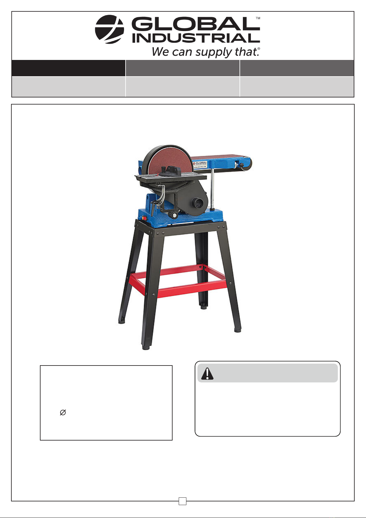
Global Industrial 133720 User manual

User's manual Manual del usuario Manuel de l'utilisateur
Customer Service
US: 1-800-645-2986
Servicio de atención al Cliente
US: 1-800-645-2986
Service à la clientèle
Canada: 888-645-2986
WARNING
Read and understand all instructions
before operating this machine. Failure
to follow these instructions may result
in electric shock, re, and/orserious
injury
SPECIFICATIONS
Motor: 1100W
Belt Width: 6"
Belt Length: 48"
Belt Speed: 7m/s
Disc : 9"
Disc Speed: 1800 RPM
Table Dimensions: 11 13/16" x 5 7/8"
1
Combination Belt and Disc Sander
Model(s): 133720

Combination Sander
2
SAFETY INSTRUCTIONSSAFETY INSTRUCTIONS
1. Keep your work area clean and well lit. Always keep the work area free of obstructions, grease,
oil, trash, and other debris.
2. Never operate this machine in the presence of ammable liquids, gases, or dust. Power tools
create sparks which may ignite the dust or fumes.
3. Keep bystanders, children, and visitors away while operating this machine. Distractions can lead
to serious injury or property damage. Protect others in the work area from debris such as chips
and sparks. Provide barriers or shields as needed.
4. Never leave sander unattended while running.
5. Do not touch grounded surfaces such as pipes, radiators, ranges, and refrigerators when
operating on electrical components. There is an increased risk of electric shock if your body is
grounded.
6. Do not expose the machine to rain or wet conditions. Water entering a power tool will increase
the risk of electric shock.
7. Grounded tools must be plugged into an outlet properly installed and grounded in accordance
with all local codes and ordinances. Never remove the grounding prong or modify the plug in
any way. Do not use adapter plugs. Check with a qualied electrician if you are unsure if the
outlet is properly grounded. If the tools should electrically malfunction, grounding provides a
low resistance path to carry electricity away from the user.
8. Do not use sander if power switch does not work. Cease operation and repair switch or replace
sander
9. Keep the Power Cord away from heat, oil, sharp edges, or moving parts. Cease operation and
replace Power Cords immediately if damaged.
10. Disconnect power cord before making any adjusments, maintenance, or storing the machine.
11. If you are using the sander outdoors, use an outdoor extension cord.
12. Avoid Accidental start-ups, make sure power switch is in "OFF" position before plugging in the
power cord.
13. Never use this machine when tired or under the inuence of drugs, alcohol, or medication.
14. Dress properly. Do not wear loose clothing or jewelry. Contain long hair. Keep your hair, clothing,
and gloves away from moving parts. Loose clothes, jewelry, or long hair can be caught in moving
parts and may cause serious personal injury.
15. Remove adjusting keys or wrenches before turning the sander on. A wrench or a key that is left
attached to a rotating part of the machine is dangerous may result in personal injury.
16. Use safety equipment. Always wear eye protection. Dust mask, non-skid safety shoes, hard hat,
or hearing protection should be used in certain conditions depending on workpiece and work
environment.
17. Check for misalignment or binding of moving parts, breakages, and any other conditions that
may impede operation of the sander. Do not operate the sander if damages, have the machine
serviced before next use.
18. Do not use third party or aftermarket accessories, they may impare operation of the sander or
malfunction during normal use.
19. Maintain all labels and nameplates on the machine so that they are clearly visible and legible

3
Combination Sander
1. Install the machine on a at, level surface that is sturdy enough to support the weight and
vibrations of the sander.
2. Always wear protective safety glasses or goggles when operating the machine.
3. Do not place workpiece against belt or disc before turning power switch on. Turn on the sander
before and allow the belt or disc to come up to full speed before sanding or grinding.
4. Check belt tracking before using belt sander. Turn belt sander on then o to observe, belt should
stay centered on the idler and drive drums. If belt is o center, unlock belt tracking locking knob
and adjust belt tracking nut as needed. Check if belt is centered after adjustment, tighten the
belt tracking locking knob and turn belt sander on and o as before. If belt is still not centered,
unlock again and continue to adjust.
5. Hold workpiece securely with both hands when sanding to sanding to prevent kickback. Keep
ngers away from abrasive to prevent injury.
6. Check all nuts, bolts and screws for tightness regularly. Vibration during operation may cause
hardware to loosen.
7. Do not use the right side of the disc for sanding, the workpiece may kick back.
8. Always maintain a maximum 1/16" clearance between the table and the sanding disc.
9. Use a dust extractor to remove woodchips and sawdust during operation.
10. Replace abrasives when they have become loaded/glazed, or when they have become frayed or
otherwise damaged.
OPERATION INSTRUCTIONSOPERATION INSTRUCTIONS
Dust Exhaust Belt Tracking Nut
Belt Tracking
Locking Knob
Power Switch
Table Angle Indicator

4
fCombination Sander
ASSEMBLY INSTRUCTIONSASSEMBLY INSTRUCTIONS
Parts ListParts List
CONTENTSCONTENTS
Ref.Ref. Ref.Ref.Qty.Qty. Qty.Qty.DescriptionDescription DescriptionDescription
Belt Sander
Table Assembly
Disc Housing Assembly
Support Bar
V-Belt
Driving Pulley (small)
Driven Pulley
Work Stop
Dust Exhaust
Sander Disc
Hex Key
Rubber Foot
Abrasive Disc
Miter Gauge Assembly
Leg
Frame (short)
Brace (short)
Frame (long)
Brace (long)
Hardware bag (not shown)
1
1
1
1
1
1
1
1
1
1
1
4
1
1
4
2
2
2
2
1
11
12
13
14
15
16
17
18
19
20
1
2
3
4
5
6
7
8
9
10
1
4
2
13
7
14
16
11 12
8
15
5
10
6
3
Note:Note:
Conrm that you have all components before beginning assembly
9
17
18
19

1. Begin Assembly by attaching short frames (16) and braces (17) to the legs (15) using M6 x 12mm
carriage bolts, 6mm at washers and M6 hex nuts to create the stand.
2. Attach long frames (18) and braces (19) to assembled legs with the same hardware as mentioned
in the previous step.
M6 Bolt
3. Turn stand assembly upside down and attache 4 rubber
feet (12) using M8 x 25mm socket head bolts, 8mm at
washers and M8 hex nuts
4. Turn stand assembly right-side up and place Belt Sander
(1) on top of the stand so that the mounting are aligned
and attach using M8 x 16mm hex head bolts, 8mm lock
washers and 8mm at washers.
5. Mount Work Stop (8) to Belt Sander (1)
using a M8 x 20mm hex head bolt and
8mm at washer.
M6 Bolt
M8 Bolt
M8 Bolt
M8 Bolt
Work Stop
Combination Sander
5

Disc
Housing
Assembly
M8 Bolt
10. Place the Sander Disc (10) onto the end of the sander shaft. Secure the Sander Disc using the M8
x 10mm set screw. There is a square access hole in the Disc Housing Assembly (3) to allow you to
use the Hex Key (11).
11. Place the sticky Abrasive Disc (13) over the Sander Disc (10). Take care to ensure Abrasive Disc is
properly adhered to Sander Disc before Proceeding.
V-Belt
Driven Pulley
Hex Key
Driving Pulley
5. Remove the disc cover and attach the Disc
Housing Assembly (3) using M8 x 20mm hex
head bolts and 8mm at washers.
6. Slide the Driven Pulley (7) onto the belt sander
shaft and insert a 5 x 55mm machine key.
7. Slide the Driving Pulley (6) onto the motor
shaft and insert a 5 x 25mm key.
8. Align the two pulleys and insert a M8 x 10mm
set screw into each one. Tighten the set screws
using the Hex Key (11).
9. Attach the V-Belt (5) to the pulleys.
Sander Disc
Hex Key Abrasive Disc
6
Combination Sander

7
Combination Sander
12. Attach Disc Cover using sheet metal screws.
13. Insert Support Bar (4) through through-hole A shown
in gure to the left. Secure using M8 x 20mm set
screw.
14. Slide Table Assembly (2) onto Support Bar (4) and
secure using M8 x 10mm set screw.
15. Using a square, ensure that the table is perpendicular
to the disc sander. Secure the table in this position.
16. To use table assembly with belt sander, repeat steps
13 through 15 using through-hole B shown in gure
to the left.
Disc Cover
Through-Hole A
Through-
Hole B
M8 Set Screw
M8 Set Screw
Belt Sander Table Conguration
17. Attach Dust Exhaust (9) using a M6 x 10mm pan
head screw.
M6 Screw
Sheet
Metal
Screw

8
Combination Sander
ADJUSTMENTS AND TOOLSADJUSTMENTS AND TOOLS
Adjusting Belt Sander Angle:Adjusting Belt Sander Angle:
1. There is a hex nut holding the belt in position. To adjust the belt sander angle, loosten the nut,
then tilt belt sander to horizontal position, vertical position, or any in between. Tighten nut once
desired angle is achieved.
2. Stops are provided for horizontal and vertical positions.
Adjusting Table Angle:Adjusting Table Angle:
3. Loosten the table locking knob, then tilt table to desired angle and tighten the locking knob.
Indices on table assembly will show table angle.
4. Loosten the set screw on the support bar to adjust table position. Move the table to within 1/16"
of the abrasive, then tighten the set screw.
Using The Miter Gauge:Using The Miter Gauge:
5. Use miter gauge to maintain a precise angle when sanding, and also to secure the workpiece for
a more even nish.
Hex Nut
Locking Knob
MAINTENANCEMAINTENANCE
WARNING
Before performing any inspection,
cleaning, or maintenance procedures,
make sure the machine's power switch
is in the "OFF" position and that the
power cord is unplugged.
1. Check for loose hardware, misaligned or binding belts, or any other conditions that may impede operation
of the sander before each use.
2. The machine vibrates during normal operation, however if abnormal noise or vibration occurs, cease use
of the sander and do not continue operation until the problem has been corrected.
3. Apply paste wax to the table to make feeding and pivoting the workpiece easier.
4. Use compressed air to clear work surfaces and moving parts of dust and debris produced by sanding.
5. Change abrasive surfaces whenever they are glazed or damaged.

9
Combination Sander
TROUBLE SHOOTINGTROUBLE SHOOTING
Table of contents
Other Global Industrial Sander manuals