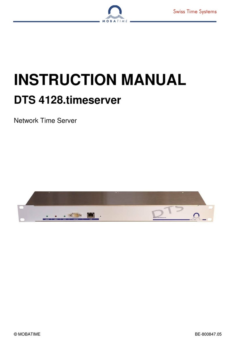
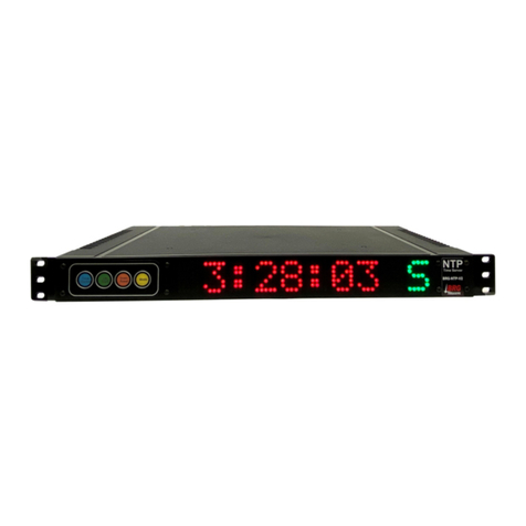
GlobalTime Electronic GTT-200 User manual

GlobalTime NTP Products
1
Tel:+86-21-36531186
Fax:+86-21-36531185
Web: www.ntpclock.com
Email: contact @ntpclock.com
Add: A2-1, No.399 Dakang Road, Baoshan District, Shanghai,China
Zip c ode: 200 4 4 3

GlobalTime NTP Products
2
Catalog
Catalog
·········································································································
2
Chapter 1 The basic information and packaging ································································ 3
1.1 Key features ··································································································································· 4
1.2 Packaging
······································································································································
4
1.3 Outline
············································································································································
5
1.4 The device profile description ····································································································· 6
Chapter 2 Hardware installation and commissioning
························································
7
2.1 The device structure
·····················································································································
7
2.2 O utdoor i nstallation
·······················································································································
7
2.3 In door installation ·························································································································· 9
Chapter 3 Equipment m aintenance
····················································································
10
3.1 Indicator state
······························································································································
10
3.2 The keyboard display ················································································································· 10
3.3 Server c onfiguration d ebugging ······························································································· 11
3.3.1 User l ogin ······························································································································ 12
3.3.2 Change network setting
······································································································
12
3.3.3 NTP c onfiguration
················································································································
13
3.3.4 SNMP s etting ······················································································································· 14
3.3.5 Heartbeat check (optional function) ·················································································· 14
3.3.6 NTP status ···························································································································· 15
3.3.7 GPS status
····························································································································
15
3.3.8 System function ··················································································································· 15
3.3.9 Chage the password ··········································································································· 16
3.3.10 Exit ······································································································································· 16
3.4 Time server log in through the network
····················································································
16
3.4 .1 Time zone display function ...................................................................................... 1 7
3.5 Remote dial-up maintenance
····································································································
1 8
3.6 Time server log in through the web browser
···········································································
1 9
3.6.1 The log in interface ··············································································································· 1 9
3.6.2 Network settings ·················································································································· 2 0
3.6.3 NTP settings
·························································································································
2 1

GlobalTime NTP Products
3
3.6.4 SNMP settings ····················································································································· 2 2
3.6.5 Check the status
··················································································································
2 2
3.7 Client c onfiguration
·····················································································································
2 3
3.8 Troubleshooting ·························································································································· 2 5
3.8.1 All indicator lights are off when power is on ···································································· 2 5
3.8.2 Receiving no satellite signals for a long t ime ·································································· 2 5
3.8.3 C an not ping the time server
····························································································
2 5
3.8.4 Instab le satellite signal, and the machine is in hold mode sometimes ························ 2 6
3.8.5 The client can not receive timing service ········································································· 2 6
3.8.6 How to configure the network equipment to receive time service ································ 2 6
Chapter 4 Detailed performance index of the equipment
···············································
2 7
Chapter 5 Appendix ·············································································································· 2 8
Chapter 1 The basic product information and packaging
GTT-200 network time server is the p r ofessional network equipment providing high-stab le
time source . GTT-200 network time server receives GPS satellite signals and extract s the
timing information to adjust the server's local time . It distributes standard time via NTP
protocol (Network Time Protocol) . If a PC or server need s time synchronization services, it

GlobalTime NTP Products
4
will run a client program to read the NTP protocol, derive time information, and modify the
time of related equipment.
The n etwork time server is widely used in telecommunications, finance, taxation, public
security and other special networks as well common corporate networks to unif y the
network time.
1.1 Key features
Serves as stratum 1 time server, receive signal from GPS s a t e llite, or GPS and
GLONASS dual satellite(optional), or from external serial port. Can be set as slave time
server to synchronize with host time server.
Adopt RFC1119/1305 NTP protocol (Network Time Protocol) to delivery time
Support RFC1769/2030 SNTP protocol (Simple Network Time Protocol)
Different client programs suppo rt, 98/2000/NT/XP, Linux, Unix, FreeBSD and other
operating systems
Two 10/100M BaseT adaptive network port s
Response capability per unit time: >1000 times per second
The GPS receiving system supports position-holding mode which greatly improves the
functionality of the system
OCXO can be built-in to guarantee the accuracy of time-keeping
Support SNMP, with the serial port to enter
6 lamps display the device working status
1.2 Packaging
Please check the shipping package which should contain the following items:
(1) GTT-200 network time server
(2) Power cable
(3) GPS antenna cable
(4) GPS satellite receiving antenna and the mounting support
(5) This user manual
(6) The software CD
(7) The packing list

GlobalTime NTP Products
5
1.3 Outline
With the rapid development of modern society, higher demand on the time precision and
frequency is put on the agenda. Nowadays with the development of modern digital
communication networks and the information superhighway construction, the political,
cultural, technological and social information coordination is based on a strict system of time
synchronization, especially in the communications, electricity, financial securities, computer
networks , production line operation, administration and national defense and other fields
urgently need the tim e synchronization equipment .
Global Positioning Satellite (GPS) signals act as the reference source of GTT-200 network
time server. The time reference contained in the GPS satellite signals synchronize s with the
universal time coordinat ed (UTC) . The long-term frequency stability has achieved the10-13
level of magnitude of cesium atomic clock, which is equivalent to be only 1 second slower
during 30 years. To adjust local time with t his reference signal can eliminate the
accumulation of deviation resulted from the low accuracy of local clock time and also can
greatly improve the timing precision of the server.
GTT-200 network time server use the professional GPS timing receiver . It can receive and
lock the satellite signal fast and reliabl y .
NTP protocol (Network Time Protocol) is a common international network timing protocol. Its
principle is to launch a time polling to the server after an interval of time through the client.
A ccording to a certain filtering algorithm it can calculate the time deviation between the
server and the client as well as the propagation delay caused by network transmission . T hen
according to these two parameters to adjust the client's local time and make it consistent
with the server. Compared to other time calibration pro t ocols, NTP protocol can eliminate
the impact caused by network transmission delay, so it can provide high-precision timing
services. Detailed description can be refer red to the latest protocol standards documents
RFC1305 and RFC2030. GTT-200 n etwork time server can be compatible with NTP v2 / v3 /
v4 in various versions.

GlobalTime NTP Products
6
1.4 The device profile description
The front panel description:
3 2 1 0
监测 天线
I
0
I
0
Synchronized
*
2009
/
01
/
01 08
:
35
:
26
OK
NTP
GPS
ocxo
M / S
POW
1
POW
2
GLOBALTIME
Figure 1-1 The front panel
The front panel:
VFD display, to show the basic status of the device and the current UTC time
The keyboard, to check and modify the system configuration
Two power lights, to indicate the two-way power supply
Four indicator lights, to indicate the service status of GPS and NTP
The back panel :
Two power sockets with fuse . After opening the fuse base, there are a primary and a
reverse fuse with specification of 0.5A on each side to facilitate users ’ r eplacement.
One anten n a plug as well as 50 ohm BNC Socket on the panel.
Two 10/100M adaptive network port s
One serial port for monitoring.

GlobalTime NTP Products
7
Chapter 2 Hardware installation and commissioning
2.1 The device structure
Figure 2-1 Device structure
GTT-200 network time server consists of the outdoor part and interior part. The outdoor part
is composed of the GPS satellite receiving antenna, surge arrester and antenna amplifier
(optional). The function is to complete the reception of satellite signals.
The interior part is the master device of GTT-200 network time server to complete the
functions of the satellite signal demodulation, the local clock calibration, achieving NTP
protocol and so on. It provides NTP timing service to other network equipment by 10M
network ports. The following are the detail installation description of the outdoor part and the
interior part.
2.2 O utdoor installation
The outdoor part is composed of the GPS satellite receiving antenna, transmission cables
and antenna amplifier. The installation attentions are as follows:
At first, the antenna installation location needs to be carefully selected, which will
signi f icantly influence function of equipment. The antenna should be installed in high
position, and can not be blocked by , such as the roof, open top, etc. If you want to achieve
better results, you
’
d better keep the elevation angle of 15 degrees from block ing . Please do
not install the antenna inside the room , because GPS satellite signal is very weak and can
not be received indoors. It does not matter if there are trees or plastic rain shelter above the
GPS receiving
antenna
A ntenna amplifier
Light n ing arrester
T
T
T
TH
H
H
H
E
E
E
E
W
W
W
W R
R
R
R
E
E
E
E
L
L
L
L
E
E
E
E
S
S
S
S
S
S
S
S
A
A
A
A
T
T
T
TM
M
M
M
C
C
C
CO
O
O
OM
M
M
M
P
P
P
P
A
A
A
A
N
N
N
N
Y
Y
Y
Y
A
S
a
S
A
S
P
O
W
E
RGTT-200

GlobalTime NTP Products
8
antenna, but other block will influence the signal significantly. In fact, only a book above the
antenna can completely block out the satellite signal.
Second, a ntenna installation should be lower than the lightning rod or other constructions
that can attract thunderstroke and the installation location should better be 10-15 meters
away from them. GPS antenna itself is rarely struck by thunder blot but is often damaged by
the stong induced electric field resulted from the stuck buildings (the lightning rod, tower, etc)
around. In this circumstance, we should install the arrester in the cable. Normally the
arrester will be installed at the position where the cable goes through the wall. By this, the
arrester can be well earthed. The arrester should also be installed between the feeder and
the equipment. Then lead the grounding wire from the arrester and connect it to the earth.
The earth resistance should be under 4 ohm and must be firmly connected to ensure the
reliable discharge by lightning .
Sometimes the antenna can be installed outside the window, but the building must be
located in the open fields with no corner. In this way, it can receive at least half of the
satellite signal. But as a long-term using equipment , it is recommended that the antenna is
installed in high places, while the outside installation can be only adopted as a temporary
test .
The high-power microwave transmitting of the same band can not be around where the GPS
antenna is installed. In addition, we should try to avoid the GPS antenna from the direct
irradiation of high-power electromagnetic radiation.
I f the length of the feeder is less than 100 meters, the antenna and equipment can be
directly connected; between 100 meters to 200 meters, one more line amplifier is needed;
ranging from 200 meters to 300 meters, two more amplifiers are needed. If you need longer
feeder links, please contact us, GlobalTime Electronic Co., Ltd. We will provide the special
program to you. The feeder usually adopt 1 / 2 inch RF cable whose loss is 12.8dB/100m
from the United States Andrew's.
When setting up the feeder:
1. Do not bend too much, because it will result in a broken feeder conductor .
2. When we connect the feeder into the interior, it should be bent into U-shape to prevent t water
from flowing backward .
You can use GPS signal transponder to lead the signal to the interior. Generally speaking,
GPS signals can be well received within 5 m of the transponder antenna. Because of the

GlobalTime NTP Products
9
way of forwarding, it is much effective for the prevention of lightning and the protection of the
host. Problems caused by the lightning is the transponder damaged. Due to a certain
transmitting power, it is suitable for some occasions.
Table 2-1 Antenna Specifications
Frequency range 1575 ± 5MHz; RF connector N-type connectors
Polarization
Right-hand circular
polarization
Installation
Thread (M24 × 1.5)
connection
Antenna gain
≥ 3.5dB
;
Volume
φ 96 × 126mm
;
Amplifier gain
≥ 37dB
;
Operating
temperature
-45
℃~
85
℃;
Noise coefficient
≤ 1.5dB
;
Storage
temperature
-50
℃~
90
℃;
Interference
suppression
25dB(f0 ± 100MHz)
;
Humidity
0
~
100%
Power consumption
3V × 20mA
;
2.3 I ndoor in s t allation
After connecting 220V AC to the master device, the indicator light "Power" on the front panel
will light which indicate s the running of power supply is normal. To measure the BNC
antenna socket with a mu l timeter, the feed voltage should be up to 5V .
Then connect the antenna cable with the antenna socket.
Next, use a computer to pass through the IP address and network settings of the serial port
configuration time server, save and exit, then restart GTT-200 Network time server to make
the network settings take effect. After reboot, input the IP address of the PING server in
another computer to check the network settings correct or not.
Last, log on the network time server through Telnet to observe the satellite receiving state,
the information on time tracking state of the server and so on. When the server locks the
satellite time ( The indicator light on the panel turns green), GTT-200 starts to provide time

GlobalTime NTP Products
10
information to other clients within the network. The specific process of software configuration
can refer to the following chapter.
Chapter 3 Equipment m aintenance
3.1 Indicator state
Table 3-2 Indicator s tatus
Indicator Status Description
Power supply
on The power supply is normal
off The power supply is abnormal
NTP
off
The server is unlock and is searching for
the time source
green The time source is locked
GPS
off The satellite signal is not received
green The satellite signal is received
OCXO
off
No OCXO or not use OCXO for time
keeping
green Use OCXO to for time keeping
M/S
off Hot standby status
green The host status
3.2 The keyboard display
VFD display (vacuum fluorescent display), is of high brightness and wide vision. The screen
can display 20 ×2 characters. The line above shows the status while the line followed
shows the time.
When starting up, the system will show the company name: GlobalTime (about 15 seconds).
Then display: "Searching ... ... ... ... - or E", which shows that it is searching for the satellite.
After receiving the satellite signal, it will display: "Synchronizing ... ... ... .* ". The time will be
locked after 5-15 minutes and display: "Synchronized ... ... ... ..* ". "-" or "E" shown in the end
of the first line indicates not receiving the satellite signal and "*" indicates receiving the
satellite signal.

GlobalTime NTP Products
11
The second line shows the time, following the format of "year, month, day, hour", for
example: "2005/06/24 13:21:08"
Press OK to enter the display menu. There are three items:
Network Information
GPS Information
NTP Information
You can select an item with the arrow keys. The interface is shown up as two lines, of which
the one above is the current "focus line", by the right-click to expand the item while by the
left-click to return to the previous menu.
The first-level menu The second-level menu The third-level menu
Network Information Eth0 (Network port 0) IP (IP address)
MSK (Subnet mask)
GW (Gateway)
GPS Information Lat (Latitude)
Lon (Longitude)
Ht (Height)
Sat (Number of satellites)
NTP Information Stratum (Server stratum)
Root disp (Root discrepancy)
Source (Synchronous source)
The third level menu of the network information can be edited, namely IP address, subnet
mask and gateway can be edited. The key to enter into edit mode is pressing " ok " button
under the third-level menu. The focus character will be displayed with the cursor. By
pressing the up and dow n button, the cursor will modify the character display while pressing
the left and right button, it will move to the next or previous character. After the modification,
you can press the " ok " button to save settings. The settings will take effect after rebooting.
3.3 Server c onfiguration d ebugging
There are two 10/100M adaptive network port s on GTT 2 00. The default configuration is
192.168.2.8. It supports web, ssh, SNMP and NTP.

GlobalTime NTP Products
12
GTT-200 network time server can conduct maintenance and management through the local
serial cable connection or the remote telnet connection. The local connection needs to use a
cross serial cable with connectors on both sides (that is, 2,3 feet of the two sides are cross
connected). The management is carried out on the Hyper- Terminal in Windows.
Remote SSH connection needs specialized SSH client. The following example describes the
maintenance methods with local connection, so does remote maintenance.
3.3.1 User l ogin
After connecting the hyper terminal, press ENTER and you will see the login interface just
like the figure 3-2 shown. Then enter the user name " ntpuser " and the password "Users.".
Note: Pay attention to the last ".". Once log ging in, you can set your own password.
Figure 3-2 Login interface
After logging in, there will be a configuration interface. There are 9 choices. The detailed
description of each function is introduced as follow:
1. Network Information
2. NTP Configuration
3. SNMP Setting
4. Heart Beat check
5. NTP status
6. GPS status
7. System function
8. Change the password
9. Q. Exit
3.3.2 Change network setting
When you press "1 ENTER" in the main configuration interface, initially it will ask whether to
use DHCP protoc o l to assign IP address. If you would like to use DHCP protoc o l to assign IP

GlobalTime NTP Products
13
address, then select "Y". Otherwise, select "N". GTT-200 support IP address through DHCP,
but it always need a static IP address because the server needs to supply the network timing
service to other devices. As a result, in DHCP network system, the recommended
configuration is to assign a static IP address from the IP Pool of DHCP server to GTT-200 .
Other devices can use the static IP to access GTT-200 .
When it asks whether to use DHCP, If you select "N", it will prompt to enter the server IP
address, netmask and gateway IP address. Finally it will prompt whether to modify the
network configuration in accordance with settings entered, then select "Y" and it will change
the equipment configuration. This configuration can not take effect until rebooting the server.
So we need to restart the server. We can modify the network configuration for many times
before restarting the equipment, but only the last one can take effect. The configuration
interface is shown in Figure 3-4.
Figure 3-4 The network parameters configuration interface
Note: When it displays " Please restart the machine to make the change active." , press " ENTER" to
return to the previous interface. Then select "4 Exit", the setting can take effect. If directly turn off the
computer, it will result in the configuration failed. The four network ports can not be set to the same
IP.
3.3.3 NTP c onfiguration
1. NTP peer
2. NTP broadcast
3. MD5 keys
4. Select NTP MD5 key
5. Q. Exit !

GlobalTime NTP Products
14
NTP peer means that the double devices work in a peer to peer mode as the backup time
source for each other. When GPS is not working well, the spare time source can be put to
use while the levle of local time server will be reduced to 2 .
NTPbroadcast is the broadcast mode of lower timing accuracy but larger system capacity
which can reduce the network data flow.
MD5 key is the encrypted password to maintain MD5.
Select NTP MD5 key is to select one or several as the timing authentication password from
the list of MD5. It can help the client to avoid malicious attacks changing the system time.
Note: both the client side and server side should use the same password.
3.3.4 SNMP s etting
SNMP_TRAP_IP=192.168.2.101 ,TRAP the address of sending data
SNMP_TRAP_PORT=162 ,TRAP the data port
SNMP_PORT=161 ,SNMP Information query port
The above three can be modified.
3.3.5 Heartbeat check (optional function)
MASTER:N, represent whether it is started as the host
LOCALPORT:6050, Heartbeat detection port
REMOTE:192.168.1.6 ,IP address of the backup machine
WORKADDR:10.32.33.21 ,the working IP, that is, the shared IP of hot standby
WORKMASK:255.255.255.0
,
the mask of the work address
WORKGATEWAY:10.32.33.21
,
the gateway of the work address
STRATUM: 7, For heartbeat detection level, the smaller, the higher. In the case that both of
the devices have become hosts, the low-level one will be initiative to be the backup
equipment based on the negotiation.
The hot standby equipment will perform the following functions:
1. The master-slave relationship of the two servers is based on the configuration files and
the boot sequence (see under for further information), that is, if machine A is started first,
then A acts as the host while machine B is the backup one; if machine B is to started frist,

GlobalTime NTP Products
15
then B acts as the host while machine A is the backup equipment; if both of the machines
are started in the same time, then the Master (can be configured) machine is the host. After
restarting the host, it will remain to be the host.
2. In the case that both the host and the backup machine have been started, if the host is cut
off the power supply unexpected l y, the backup machine will automatically switches to the
host. The switching period is about 5s.
3. If the host is disconnected from the network unexpectedly and the backup machine is
under the normal operation of the network, the backup machine will also automatically
switches to the host.
4. GPS receiver of the host can not receive the satellite signals normally, if the network and
GPS receiver with the backup machine are both in normal operation, then the backup
machine automatically switches to the host. To prevent the devices from frequent switching
when the GPS is not working well, only when it can not receive the satellite signals for 2
minutes can the two devices switch over.
5. If the switch has broken down and machine A and B are on the ends of the fault point,
they can provide services for both the two networks. After the troubleshooting, the machine
of higher priority will be (can be set) the host while another one will be the backup
equipment.
3.3.6 NTP status
stratum=1
,
precision=-19
,
rootdelay=0.000 ,
rootdispersion=35.55 ,
Time source: GPS
,
Local time source can be internal clock, GPS, or OCXO
press Q : return
3.3.7 GPS status
Latitude: N31d18.182m represents latitude 31 degrees 18.182 minutes North.
Longitude: E121d28.8331m represents121 degrees 28.8331 minutes East longitude.
Received Satellite number: 6, the number of satellite signals received

GlobalTime NTP Products
16
press Q return !
3.3.8 System function
1 ) . ping
input target IP(Q return):
input the target IP address and then press
“
Enter
”
, by pressing
“
Ctrl +c
”
to return to the
previous sub-menu while
“
Q
”
to return to the previous menu.
2 ) . Time
Mon jul 30 19:16:31 CST 2007
Display the current system time, by pressing “Enter ”to return to the previous menu
Reset configuration
press Q return !
3.3.9 Cha n ge the password
If type "3" in the main configuration interface, it will enter into the "change password"
interface , shown as figure 3-5. At first, you need to type the original password. If correct, it
will prompt to a new password. The user password contains 5-8 characters. Note: the
password can not be too simple. If take some meaningful words as the password, it will
probably be refused by the system.
Figure 3-5 Change the password
3.3.10 Exit
type "4" in the main configuration interface, it will return to the user-login screen.
3.4 Time server logon through the network
For the sake of the system security, the time server supports login by SSH. The login
configuration is as the following interface. The interface after connecting is the same as the
HyperTerminal login.

GlobalTime NTP Products
17
SSH login configuration interface
3. 4.1 Time zone display function
Our new version allows users to configure time display on the front panel in different time
zones:

GlobalTime NTP Products
18
3.5 Remote dial-up maintenance
We can use the MODEM to achieve remote dial-up maintenance with the serial monitoring
port of GTT-200 network time server. In order to make it, please follow these steps:
Initially, set the MODEM to auto answer mode and connect the MODEM and a computer
serial port with a serial cable. Type the following three commands in the HyperTerminal:
atS0=1
at&W0

GlobalTime NTP Products
19
at&Y0
Note: The commands are case sensitive.
Then c onnect the MODEM and GTT-200 network time server monitoring port with a serial
cable. Then plug the telephone line. Finally, dial this number through the Hyper Terminal of
another computer with MODEM and it can be connected with the server. The configuration is
as introduced in section 3.2.
3.6 Time server logon through the web browser
To configure the server via IE browser
Enter the time server ’s IP address in the address bar. If It displays the following screen, then
the connection is successful. The user name is “ntpuser ”and the password is “Users ”.
Login
3.6.1 The login interface
The login screen is as shown in the Figure 1.1. The users must login the system and be
authenticated before configuring the server. The figure below is the main interface after a
successful login.

GlobalTime NTP Products
20
w elcome window
The configuration item includes: (1) Network Settings (2) NTP settings (3) SNMP settings (4)
Hot Standby (5) NTP status (6) GPS status
3.6.2 Network settings
Click “Network settings ”in the navigation bar, it will enter the network configuration item.
in the navigation bar click on "Network Settings" .
Network settings are divided into DEVICE, BOOTPROTO, IPADDR, NETMASK and
GATEWAY. They represent the network card equipment, starting mode, IP address, subnet
mask and gateway. You can select the network card settings by clicking the drop-down
menu under the DEVICE item, as shown below:
Network settings / s elect the network card .
Table of contents
Other GlobalTime Electronic Network Time Server manuals