Glowworm 56/2 User guide
Other Glowworm Boiler manuals

Glowworm
Glowworm Easicom User manual
Glowworm
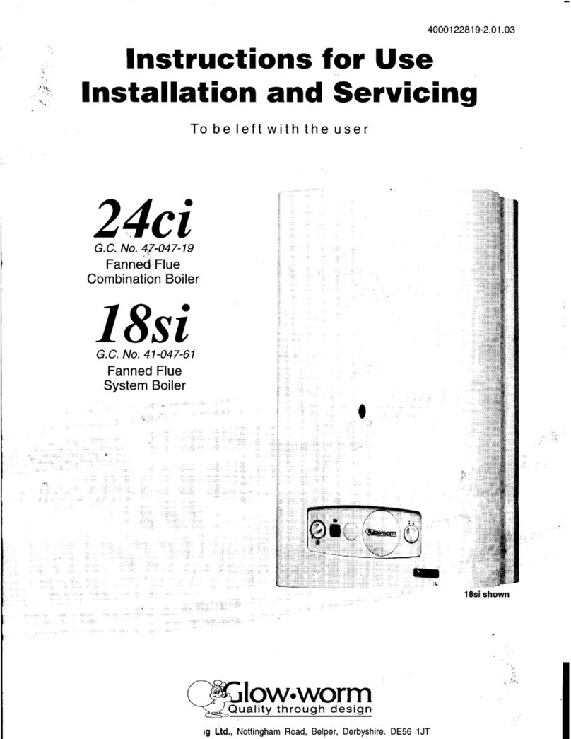
Glowworm 24ci Operating manual
Glowworm
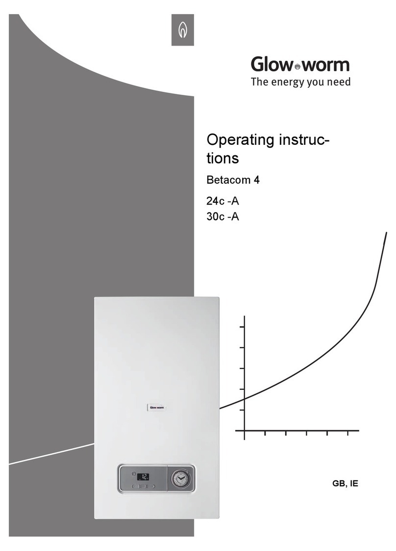
Glowworm Betacom 4 24c-A User manual

Glowworm
Glowworm Hideaway 100 Operating manual
Glowworm
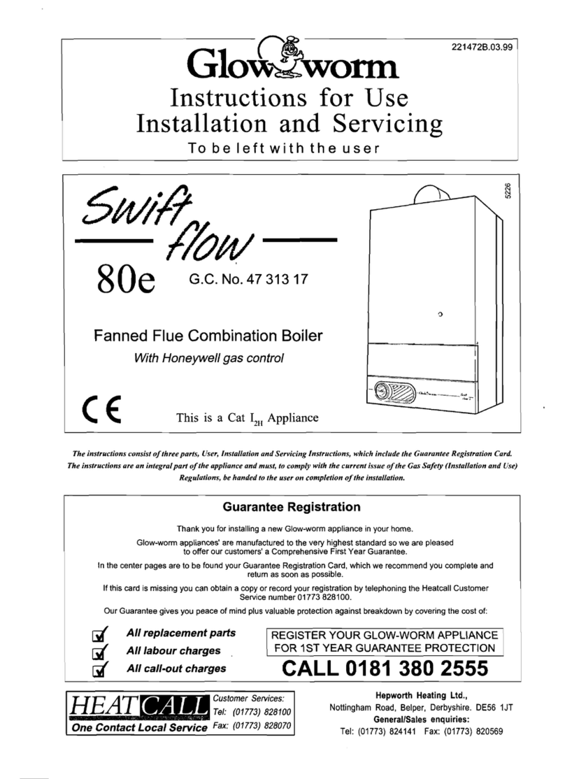
Glowworm Swiftflow 80e User manual

Glowworm
Glowworm ENERGY 12s -A User manual

Glowworm
Glowworm 12hxi User manual

Glowworm
Glowworm 12hx User manual

Glowworm
Glowworm Compact 28c-AS/1 User manual
Glowworm
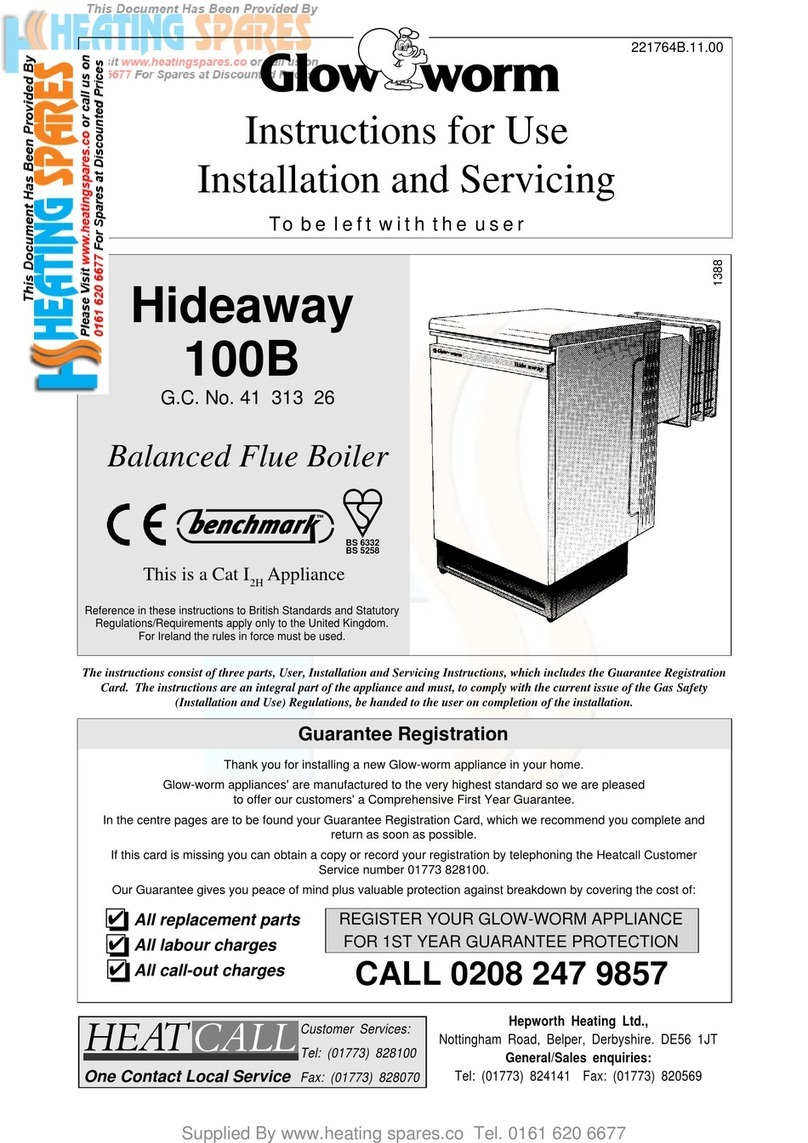
Glowworm Hideaway 100B User manual

Glowworm
Glowworm Economy Plus 60F User guide
Glowworm
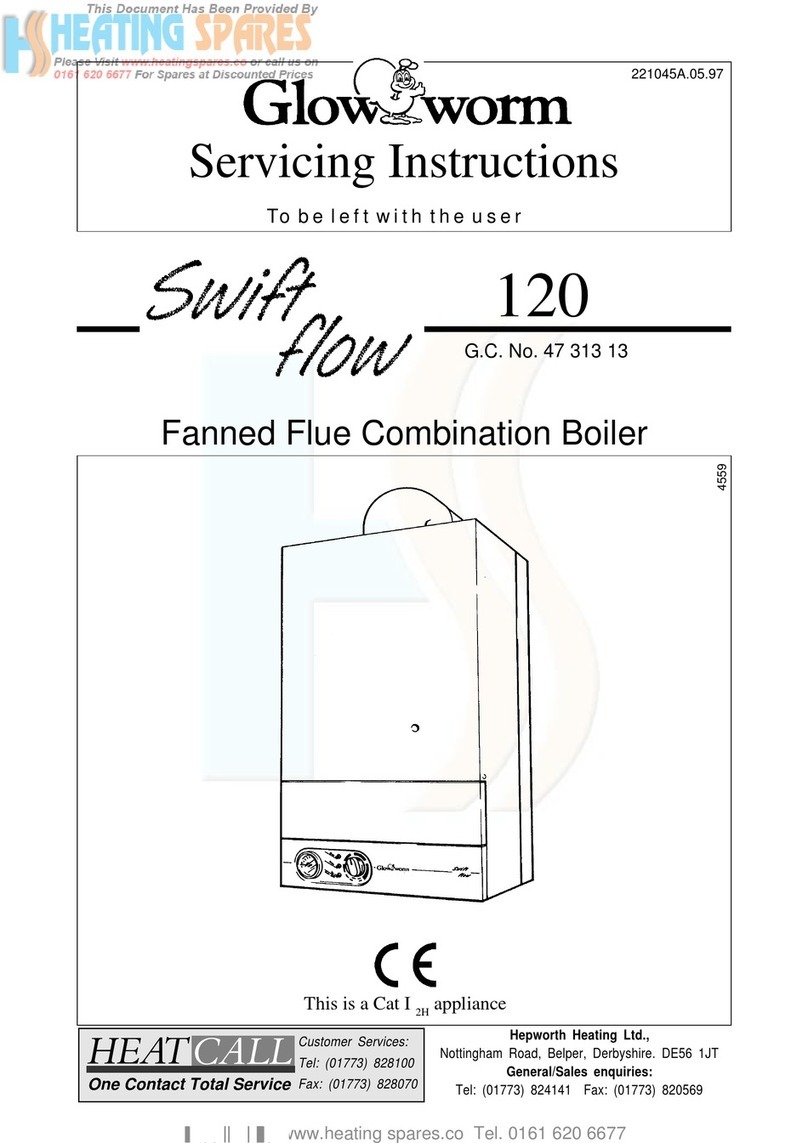
Glowworm SwiftFlow 120 User guide

Glowworm
Glowworm Energysaver 60 Operating manual

Glowworm
Glowworm Energysaver Combi 2 80 47-047-13 Operating manual

Glowworm
Glowworm 12hxi User guide

Glowworm
Glowworm economy plus c 30 User guide

Glowworm
Glowworm Micron 70FF Operating manual
Glowworm
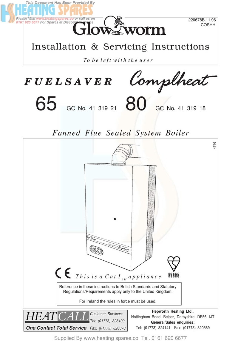
Glowworm FUELSAVER 65 User guide

Glowworm
Glowworm swift flow 75e Operating manual
Glowworm
Glowworm Xtramax HE User manual
Popular Boiler manuals by other brands

Vaillant
Vaillant uniSTOR VIH SW GB 500 BES operating instructions

Radijator
Radijator BIO max 23.1 instruction manual

Brunner
Brunner BSV 20 Instructions for use

Buderus
Buderus Logamax GB062-24 KDE H V2 Service manual

Potterton
Potterton 50e Installation and Servicing Manual

UTICA BOILERS
UTICA BOILERS TriFire Assembly instructions

Joannes
Joannes LADY Series Installation and maintenance manual

ECR International
ECR International UB90-125 Installation, operation & maintenance manual

Froling
Froling P4 Pellet 8 - 105 installation instructions

Froling
Froling FHG Turbo 3000 operating instructions

U.S. Boiler Company
U.S. Boiler Company K2 operating instructions

Henrad
Henrad C95 FF user guide

NeOvo
NeOvo EcoNox EF 36 user guide

Potterton
Potterton PROMAX SL 12 user guide

Eco Hometec
Eco Hometec EC 25 COMPACT Technical manual

Viessmann
Viessmann VITODENS 200 Operating instructions and user's information manual

Baxi
Baxi Prime 1.24 installation manual

REXNOVA
REXNOVA ISA 20 BITHERMAL Installation, use and maintenance manual
