manuals.online logo
Brands
  1. Home
  2. •
  3. Brands
  4. •
  5. Worcester
  6. •
  7. Boiler
  8. •
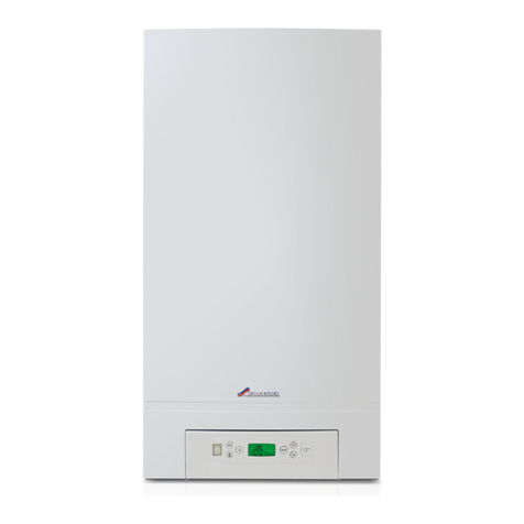
  9. Worcester greenstar heatslave 18 User manual

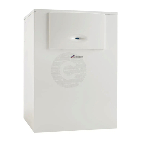
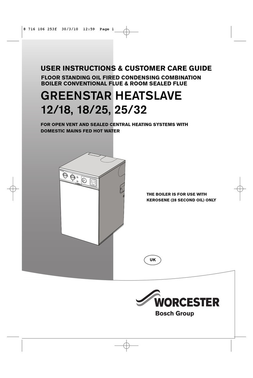
Worcester greenstar heatslave 18 User manual

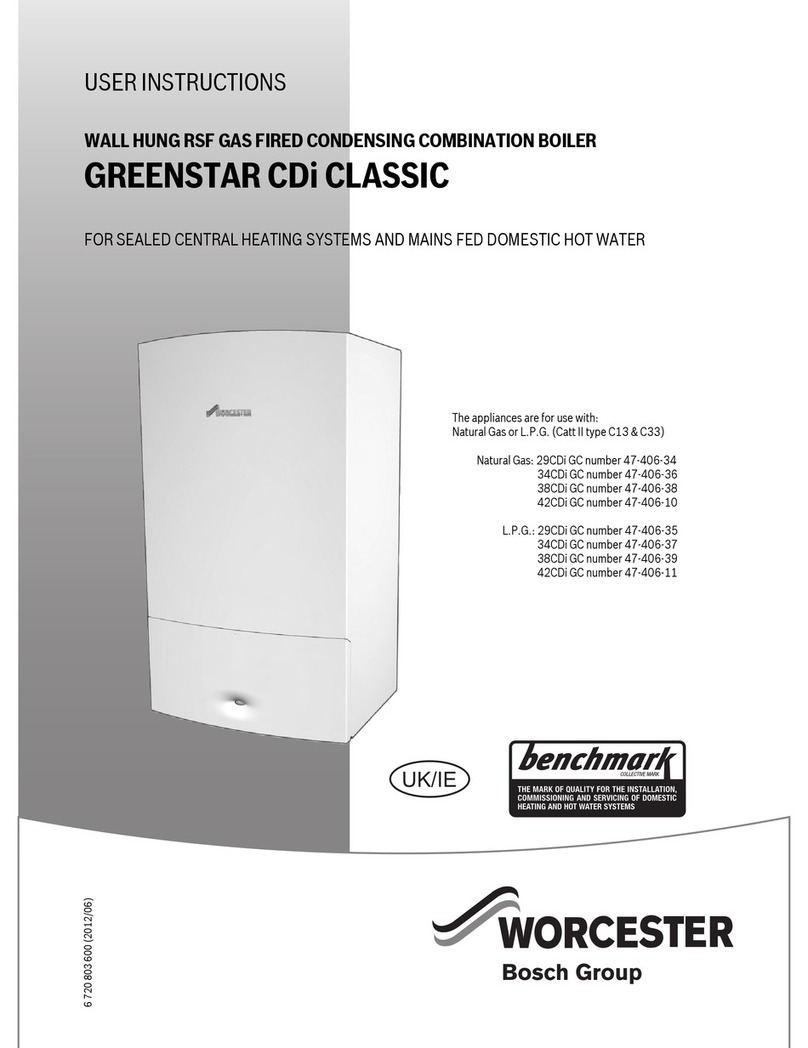
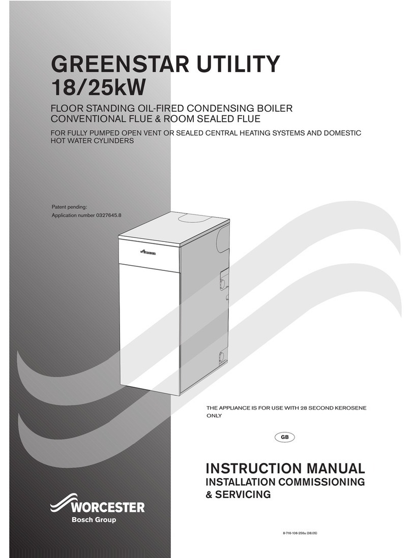
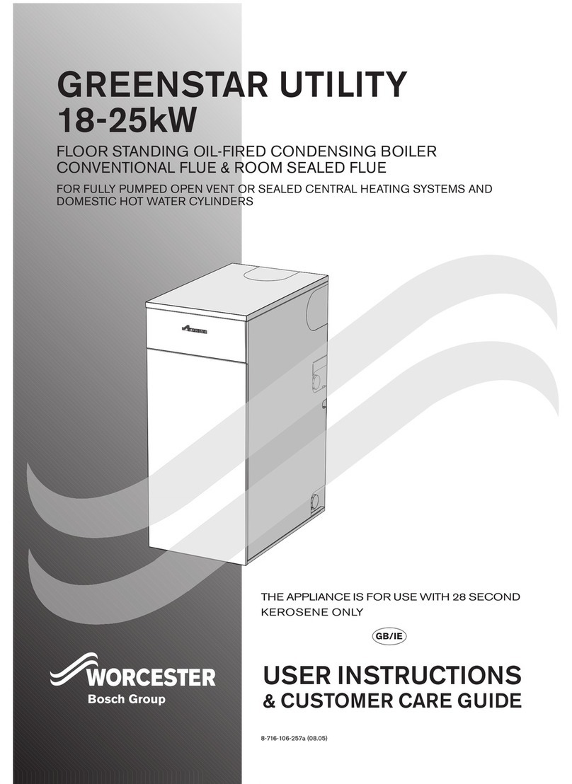
GREENSTAR HEATSLAVE
18/25
FLOOR STANDING OIL-FIRED CONDENSING COMBINATION BOILER
CONVENTIONAL FLUE & ROOM SEALED FLUE
FOR OPEN VENT AND SEALED CENTRAL HEATING SYSTEMS WITH DOMESTIC MAINS FED HOT
WATER
THE APPLIANCE IS FOR USE WITH 28 SECOND KEROSENE
ONLY
8-716-106-2 2a (03.0 )
INSTRUCTION MANUAL
INSTALLATION COMMISSIONING
& SERVICING
GB
Patent pending:
Application number 032764 .8
INSTALLATION & SERVICING INSTRUCTIONS
CONTACT INFORMATION
INSTALLATION & SERVICING INSTRUCTIONS FOR WORCESTER BOSCH
INSTALLATION &
SERVICING INSTRUCTIONS
8-716-106-2 2a (03.0 )
PLEASE READ THESE INSTRUCTIONS CAREFULLY BEFORE STARTING INSTALLATION.
THESE INSTRUCTIONS ARE APPLICABLE TO THE WORCESTER BOSCH APPLIANCE
MODEL(S) STATED ON THE FRONT COVER OF THIS MANUAL ONLY AND MUST NOT BE
USED WITH ANY OTHER MAKE OR MODEL OF APPLIANCE.
THE INSTRUCTIONS APPLY IN THE UK ONLY AND MUST BE FOLLOWED EXCEPT FOR
ANY STATUTORY OBLIGATION.
THIS APPLIANCE MUST BE INSTALLED BY A COMPETENT PERSON. FAILURE TO INSTALL
CORRECTLY COULD LEAD TO PROSECUTION.
IF YOU ARE IN ANY DOUBT CONTACT WORCESTER BOSCH TECHNICAL HELPLINE.
DISTANCE LEARNING AND TRAINING COURSES ARE AVAILABLE FROM WORCESTER
BOSCH.
PLEASE LEAVE THESE INSTRUCTIONS WITH THE USER OR WITH THE APPLIANCE
AFTER INSTALLATION OR SERVICING.
WORCESTER BOSCH:
MAIN RECEPTION: 0190 7 4624
MAIN FAX: 0190 7 4619
TECHNICAL: 0870 266241
SERVICE: 08 47 2 6206
SPARES: 0190 7 2 71
LITERATURE: 0190 7 2 6
TRAINING: 0190 7 2 26
SALES: 0190 7 2640
WEBSITE: www.worcester-bosch.co.uk
WATER TREATMENT:
FERNOX 01799 0811
www.fernox.com
SENTINEL 01 1 420 9 9
www.betzdearborn.com/sentinel
FLUE TERMINAL GUARDS:
WORCESTER BOSCH
Contact details as above
CONVENTIONAL FLUE MANUFACTURERS:
INTERACTIVE (Flue Systems) Ltd., 01908 69887
Selkirk Manufacturing Ltd. (SF Ltd.), 01271 326633
CONDENSATE PUMP MANUFACTURERS:
ASPEN 01323 848842
OIL FIRING TECHNICAL ASSOCIATION:
OFTEC 084 6 8 080
www.oftec.org
ABBREVIATIONS USED IN THIS MANUAL:
Ø Diameter
CH Central Heating
DHW Domestic Hot Water
TRV Thermostatic Radiator Valve
IP Ingress Protection
CF Conventional flue
RS Room sealed flue
N/A Not allowed
SEDBUK Seasonal Efficiency for Domestic Boilers in the United Kingdom
OFTEC Oil Firing Technical Association for the Petroleum Industry
Store the applia ce i a dry area prior to
i stallatio .
IMPORTANT HANDLING INSTRUCTIONS:
It is advised that more than one person is
involved in the transfer of the packaged
appliance from the van to the point of installation.
It is advised that no attempt should be made
to move the packaged appliance without the
use of a suitable truck.
At a times the correct method for hand ing
heavy objects shou d be strict y observed.
GENERAL HANDLING GUIDELINES:
 Lift only a manageable weight, or ask for
help.
 When lifting, bend the knees, and keep the
back straight and feet apart.
 Do not lift and twist at the same time.
 Lift and carry items close to the body.
 Wear protective clothing and gloves to
protect from any sharp edges.
SYMBOLS USED IN THIS MANUAL:
Domestic hot water
Central heating
Room thermostat
Frost thermostat
Wait time period
Programmer/timer OFF
Programmer ON CH only
Programmer ON DHW only
Programmer ON CH and DHW
Cold water main supply
Electricity supply
INSTALLATION & SERVICING INSTRUCTIONS FOR WORCESTER BOSCH CONTENTS
SAFETY &
REGULATIONS
FAULT FINDING
& DIAGRAMS
APPLIANCE
INFORMATION
PRE-
IN STALLATION
IN STALLATIONCOMMISSIONING
SERVICING
& SPARES
CONVERSION
KITS
CONTENTS
1
SAFETY & REGULATIONS
SAFETY PRECAUTIONS 2
INSTALLATION REGULATIONS 2
APPLIANCE INFORMATION
GENERAL INFORMATION 3
TECHNICAL DATA 4
LAYOUT & COMPONENTS
PRE-INSTALLATION
CLEANING PRIMARY SYSTEMS 6
MAINS SUPPLIES 7-8
WATER SYSTEMS & PIPEWORK 9-10
CONDENSATE & PRESSURE RELIEF PIPEWORK 11
BOILER LOCATION & CLEARANCES 12-13
FLUE OUTLET POSITIONS 14
CONVENTIONAL FLUE 1
ROOM SEALED FLUE OPTIONS 16
INSTALLATION
UNPACKING THE BOILER 17
PIPEWORK POSITIONS & FLUE OPENING 18
BOILER INSTALLATION 19
FLUE INSTALLATION 20
COMBUSTION CHAMBER 21
PIPEWORK CONNECTIONS 22
OIL BURNER & PUMP 23
REFIT COMPONENTS 24
ELECTRICS 2 -26
COMMISSIONING
PRE-COMMISSIONING CHECKS 27
FILLING THE SYSTEM 28
STARTING THE APPLIANCE 29-32
WATER TREATMENT 33
FINISHING COMMISSIONING 34
SERVICING & SPARES
INSPECTION AND SERVICE 3 -38
SHORT PARTS LIST 39
CONVERSION KITS
N/A
FAULT FINDING & DIAGRAMS
FAULT FINDING 40-41
ELECTRICAL SCHEMATIC 42
8-716-106-2 2a (03.0 )
SAFETY &
REGULATIONS
INSTALLATION & SERVICING INSTRUCTIONS FOR WORCESTER BOSCH
SAFETY PRECAUTIONS INSTALLATION REGULATIONS
2SAFETY PRECAUTIONS &
INSTALLATION REGULATIONS
8-716-106-2 2a (03.0 )
OIL SMELLS, LEAKS OR FUMES FROM THE APPLIANCE:
Extinguish any naked flames
Open windows and doors
Isolate the electrical supply
Isolate the fuel supply to the boiler
Rectify fault.
HEALTH & SAFETY:
The appliance contains no asbestos and no substances have been used in the construction
process that contravene the COSHH Regulations (Control of Substances Hazardous to Health
Regulations 1988). Where applicable, the CE mark indicates compliance with relative EU
Directives.
COMBUSTIBLE AND CORROSIVE MATERIALS:
Do not store or use any combustible materials (paper, thinners, paints etc.) inside or within
the vicinity of the appliance.
The combustion air must be kept clear of chemically aggressive substances which can corrode
the appliance and invalidate any warranty.
FITTING & MODIFICATIONS:
Fitting the appliance and any controls to the appliance may only be carried out by a competent
engineer in accordance with these instructions and the relevant Installation Regulations.
Flue systems must not be modified in any way other than as described in the fitting instructions.
Any misuse or unauthorised modifications to the appliance, flue or associated components
and systems could invalidate the warranty. The manufacturer accepts no liability arising from
any such actions, excluding statutory rights.
SERVICING:
Advise the user to have the system regularly serviced by a competent, qualified engineer (such
as OFTEC registered personnel) using approved spares, to help maintain the economy, safety
and reliability of the appliance.
Failure to install appliances correctly could lead
to prosecution.
The appliance should be installed by a competent
person. The person installing the appliance should
be aware of the Health and Safety at Work Act
and take appropriate action to ensure that the
regulations are adhered to. In order to give
optimum efficiency and trouble free operation the
appliance must be commissioned by a qualified
OFTEC engineer.
The compliance with a British Standard does
not, of itself, confer immunity from legal obligations.
In particular the installation of this appliance must
be in accordance with the relevant requirements
of the following British Standards and regulations
in respect of the safe installation of equipment.
BS 410: part 1: Code of practice for Oil Fired
Boilers.
BS 799: part : Specification for Oil Storage
Tanks.
BS 7 93: Code of Practice for treatment of water
in domestic hot water central heating systems.
BS 449: part 1: Specification for forced
circulation hot water central heating for domestic
premises.
BS 9 : part 8: Specification for the
installation of thermoplastic pipes and associated
fittings for use in domestic hot and cold water
services and heating systems.
BS 7291: Thermoplastic pipes and associated
fittings for hot and cold water for domestic
purposes and heating installations in buildings.
BS 7074: part 1: Application, selection and
installation of expansion vessels and ancillary
equipment for sealed water systems.
BS 7671: IEE Wiring Regulations, current edition.
The Building Regulations Part J and L1 England
and Wales; Part F and Part J Section III Scotland;
Part L and Part F Northern Ireland.
Local water company bye-laws.
The Control of Pollution (Oil) Regulations.
OFTEC Standards.
Where no specific instruction is given, reference
should be made to the relevant codes of practice.
APPLIANCE
INFORMATION
INSTALLATION & SERVICING INSTRUCTIONS FOR WORCESTER BOSCH 3
GENERAL INFORMATION
GENERAL INFORMATION
8-716-106-2 2a (03.0 )
STANDARD PACKAGE:
A - Floor standing oil fired condensing boiler for
open vent and sealed domestic central heating
and mains fed hot water.
B - Literature pack.
C - Condensate trap kit.
A
B
600mm
8 mm
20mm
C
APPLIANCE
INFORMATION
INSTALLATION & SERVICING INSTRUCTIONS FOR WORCESTER BOSCH
18/25kW
69
30
1
4
2.6
-
18
1.2
40
40
10
22
22
1
22
1
1
21.
230
0
240
/81
/72
92
10
110
<100
90.1
20
20
177
4
TECHNICAL DATA
TECHNICAL DATA 8-716-106-2 2a (03.0 )
Centra Heating
Primary water capacity (total) litres
Maximum static head metres
Minimum static head metres
Available pump head (20°C difference) metres water
Max. permissible sealed system operating pressure bar
Flow restrictor colour
Domestic Hot Water
Maximum flow rate (±1 %) litres/min
Minimum inlet pressure (dynamic) for maximum flow rate bar
Maximum hot water temperature rise for 90 litres draw off (@18 litres per min) °C
F ue
Exit flue gas mass flow kg/hr
Pipework connections
Fuel line (compression) mm
CH flow mm
CH return mm
Water main inlet mm
DHW outlet mm
CH vent (optional) inch BSP
CH drain inch BSP
Condensate (polypropylene) mm
E ectrica
Electrical power supply voltage AC...V
Frequency Hz
Max. power consumption W
Thermostats
CH control thermostat range (cut in/cut out) °C
DHW control thermostat range (cut in/cut out) °C
CH & DHW control thermostat differential °C
Boiler high limit thermostat set point °C
Boiler manual reset overheat thermostat set point °C
Flue reset overheat thermostat set point °C
Genera Data
Maximum hearth temperature °C
SEDBUK (Band A) %
Appliance protection rating (with programmer blanking plate fitted) IP
Appliance protection rating (with fascia programmer fitted) IP
Weight (excluding packaging) kg
DESCRIPTION UNITS
APPLIANCE
INFORMATION
INSTALLATION & SERVICING INSTRUCTIONS FOR WORCESTER BOSCH 5
LAYOUT & COMPONENTS
LAYOUT & COMPONENTS
8-716-106-2 2a (03.0 )
The diagram opposite excludes the top,front and
RH side casing panels.
1 CONTROL BOX ASSEMBLY
2 CASING SIDE PANEL
3 DIVERTER VALVE
4 FLUE 'KNOCK-OUT' SECTION
AUTO AIR VENT
6 CH CONTROL & MANUAL RESET HIGH
LIMIT THERMOSTATS
7 CIRCULATING PUMP
8 OVERHEAT THERMOSTAT (AUTOMATIC
RESET)
9 PRESSURE RELIEF VALVE
10 EXPANSION VESSEL
11 DHW HEAT EXCHANGER
12 CASING SUPPORT PANEL
13 MANUAL RESET FLUE OVERHEAT
THERMOSTAT
14 FLUE MANIFOLD ACCESS COVER
1 FLUE GAS SAMPLING POINT
16 CLIP FOR FIRE VALVE SENSOR
17 CLIP FOR POWER CABLE
18 AIR INLET PIPE & CASING
19 SECONDARY HEAT EXCHANGER MANUAL
AIR VENT
20 SECONDARY HEAT EXCHANGER DRAIN
21 CONDENSATE OUTLET PIPE
22 SECONDARY HEAT EXCHANGER
23 PRIMARY HEAT EXCHANGER
24 TRAY
2 COMBUSTION CHAMBER ACCESS DOOR
26 DATA LABEL
27 HEATSLAVE TANK DRAIN COCK
28 HEATSLAVE TANK
29 PRESSURE GAUGE
30 QUICK REFERENCE GUIDE SLOT
31 LOCK-OUT INDICATOR
32 POWER ON INDICATOR
33 OVERHEAT RESET BUTTONS (water
temperature & flue temperature)
34 LOCK-OUT RESET BUTTON
3 CH TEMPERATURE CONTROL
36 DHW TEMPERATURE CONTROL
37 BENTONE STERLING 0 BURNER
i) Control box
ii) Motor
iii) Air intake casing
iv) Oil pump
v) Combustion head
38 CLIP - AIR INTAKE HOSE
39 AIR INTAKE HOSE
OPTIONAL ACCESSORIES ( ot supplied)
a - 7 day TWIN CHANNEL DIGITAL TIMER
Part No. 7 716 192 033 0
1
3
6
789
2
4
10
11 12 13
16
34
33
32
31
36
23
29
21
22
3
30
14
i)
38
37
ii)
iii)
iv)
v)
a
1
39
17 18 19 20
24
2
26
27
28
PRE-
IN STALLATION
INSTALLATION & SERVICING INSTRUCTIONS FOR WORCESTER BOSCH
6
CLEANING PRIMARY SYSTEMS
IMPORTANT:
Debris from the system can damage the
boi er and reduce efficiency. Fai ure to comp y
with the guide ines for the use of water
treatment with the app iance wi inva idate
the app iance warranty.
BEFORE CLEANING THE SYSTEM:
ENSURE THE SYSTEM AND PIPEWORK IS IN
GOOD WORKING ORDER.
USE THE EXISTING BOILER/CIRCULATING
PUMP WHERE POSSIBLE OR USE A POWER
FLUSHING MACHINE TO AID THE CLEANSING
PROCEDURE BEFORE INSTALLING A NEW
BOILER.
CLEANING THE PRIMARY SYSTEM:
Cleanse the system in accodance with BS7 93.
Fill the system with cold mains water to the
recommended pressure and check for leaks.
Open all drain cocks and drain the system.
Close drain cocks and add a suitable flushing
agent at the correct strength for the system
condition in accordance with the manufacturer's
instructions.
Circulate the flushing agent before the boiler is
fired up.
Run the boiler and system at normal operating
temperature in accordance with the
manufacturer's instructions.
Drain and thoroughly flush the system to remove
the flushing agent and any debris.
CAUTION: ISOLATE THE MAINS SUPPLIES BEFORE STARTING ANY WORK
AND OBSERVE ALL RELEVANT SAFETY PRECAUTIONS.
IMPORTANT: A the fo owing pre-insta ation sections must be read and requirements
met before starting boi er or f ue insta ation.
8-716-106-2 2a (03.0 )
PRE-
IN STALLATION
INSTALLATION & SERVICING INSTRUCTIONS FOR WORCESTER BOSCH
8-716-106-2 2a (03.0 )
7
MAINS SUPPLIES
ELECTRIC SUPPLY:
 Supply: 230V - 0Hz
 Cable: PVC insulated 0.7 mm² (24 x 0.2mm)
temperature rated to 90°C
 Protection IP20
 External A fuse to BS1362
 The appliance must be earthed
 All pipes to the boiler must be cross-bonded
 It must be possible to isolate the appliance from
the electric supply with at least a 3mm contact
separation in all poles supplying the appliance
 Wiring between the appliance and the electrical
supply must comply with IEE wiring regulations
and any local regulations which may apply for
fixed wiring to a stationary appliance
 Any system connected to the boiler must not
have a separate electricity supply
WATER SUPPLY:
The following are general requirements and if
necessary the advice of the local water company
should be sought before fitting the appliance.
 The appliance cold water supply should be the
first connection off the water main where
possible.
Water Mai s Pressure:
 Minimum dynamic mains water pressure 1.2 bar
for maximum performance
 Maximum mains fed water pressure 10 bar. If
necessary, fit a pressure reducing valve
IMPORTANT: Non-return, back f ow
prevention devices (inc uding those
associated with water meters) fitted to the
mains water supp y can cause a pressure
bui d up which cou d damage the boi er and
other househo d app iances.
 Where the water main supply has a non-return,
back flow prevention valve fitted, a mini expansion
vessel (A) should be connected to the mains
water inlet pipe (B) between the non-return valve
(C) and the boiler (D) as shown opposite.
Use i hard water areas:
Normally there is no need for water treatment to
prevent scale formation as the maximum temperature
of the heat exchanger is limited by the electronic
control circuit.
In areas where the temporary water hardness
exceeds 200ppm, consideration may need to be
given to the fitting of a scale prevention device. In
such circumstances, the advice of the local water
authority should be sought.
MAINS SUPPLIES
D
C
A
B
MAINS WATER EXPANSION VESSEL:
A - Mini expansion vessel, part No. 7 716 192 10
B - Water Main supply pipe
C - Non-return valve
D - Boiler
PRE-
IN STALLATION
INSTALLATION & SERVICING INSTRUCTIONS FOR WORCESTER BOSCH
8-716-106-2 2a (03.0 )8-716-106-2 2a (03.0 )
8MAINS SUPPLIES
OIL SUPPLY:
 Plastic or steel tanks should be installed to
BS 410. A steel tank should conform to BS799:
part and have a slope of 1 in 24 away from
the outlet valve with a sludge cock at its lower
end.
 Do not use ga vanised stee tanks or pipework
for the oi supp y system.
 Do not use so dered joints on the oi supp y
pipework as this cou d cause a hazard in the
event of a fire.
a) Si gle pipe gravity feed system:
The oil storage tank (A) must be positioned so that
the oil level does not exceed 4 metres above the
level of the burner oil pump (J) and in addition the
oil level must be at least 300mm above the oil pump
(J). Where the maximum oil level in the oil storage
tank exceeds 4 metres, a head breaking device
must be installed between the tank (A) and the
burner oil pump (J).
b) Double pipe sub-gravity feed system:
Maximum suction height 3. metres. Non-return
valves must be fitted to the inlet and return oil line
between the oil pump (J) and oil storage tank (A).
c) Si gle pipe suctio lift with de-aerator
Maximum suction height 3. metres. The oil tank
(A) must be positioned below the oil pump (J).
Create an inlet and return loop between the de-
aerator (M) and oil pump (J).
A non-return valve must be incorporated within the
de-aerator or fitted to the oil line between the oil
storage tank (A) and the de-aerator (M).
A top feed oil tank fitted with a de-aerator using
an internal non-return valve should have any non-
return valve/s fitted in the base of the tank to the
suction line removed to assist purging air from the
oil line.
Pipework
Use copper pipe of the correct diameter
according to the information shown opposite.
Use flexible hoses to connect to the oil pump
(J).
Lay the oil supply pipe (H) as straight and level
as possible to avoid air pockets and unnecessary
friction losses. Route away from the boiler access
door or other hot surfaces.
Install a manual isolating valve (B) to the oil
supply pipe (H), as close to the oil storage tank
(A) as possible.
Fit an oil filter (C) to the oil supply pipe, near the
oil storage tank. If there is doubt about the
internal condition of the oil supply pipe, fit an
additional oil filter (recommended paper filter
element) close to the boiler, but not inside the
boiler casing.
Fit a fire valve in accordance with BS 410. The
fire valve (D) should be fitted externally to the
building with the fire valve sensor (F) located
within the appliance case.
A capillary type valve provides a neat and simple
installation. Alternatively, a fusible link or electrical
system may be used.
Under no circumstances shou d a combination
iso ating/fire va ve be used as the so e fire
protection device.
MAINS SUPPLIES
AF
BC
G J
4m (13ft) max.
K
E
A - Oil storage tank
B - Isolating valve
C - Oil filter
D - Fire valve to BS 410
E - External wall
F - Fire valve sensor
G - Oil burner
H - Oil supply pipe
J - Oil pump
K - Full base (plastic tanks)
L - Non-return valve
M - De-aerator
a)
N TE: All dimensions are in metres unless stated otherwise.
The maximum pipe run figures are based on using copper pipe with an inside diameter
of 2mm less than the Ø.
HB DB C
300mm
min.
HEAD 10mmØ 12mmØ
0. 12 30
1.0 2 69
1. 37 91
2.0 49 100
HEAD 10mmØ 12mmØ
2. 62 100
3.0 74 100
3. 87 100
4.0 99 100
MAXIMUM PIPE RUN FOR SINGLE PIPE GRAVITY FEED SYSTEM
B
A
DB
CB
E
K
3. m (11. ft) max.
1 0mm
L
L
b)
H
F
C
G
J
HEAD 10mmØ 12mmØ
0 0 100
0. 44 100
1.0 38 9
1. 32 80
HEAD 10mmØ 12mmØ
2.0 26 66
2. 20 0
3.0 14 37
3. 8 22
MAXIMUM PIPE RUN FOR DOUBLE PIPE SUB-GRAVITY FEED SYSTEM
The table and illustration above is a guide only and does not in any way override the de-aerator
manufacturers instructions.
HEAD 2. kg/h kg/h 10kg/h 10kg/h
8mmØ 8mmØ 8mmØ 10mmØ
0 100 26 100
0. 9 4 23 100
1.0 80 40 20 90
1. 70 3 17 7
HEAD 2. kg/h kg/h 10kg/h 10kg/h
8mmØ 8mmØ 8mmØ 10mmØ
2.0 60 30 14 6
2. 4 2 11 0
3.0 3 1 8 3
3. 2 10 20
MAXIMUM PIPE RUN FOR SINGLE PIPE SUCTION LIFT WITH DE-AERATOR
FUEL FLOW RATE FUEL FLOW RATE
B
A
M
B
F
CJ
K
3. m (11. ft) max.
E
D
c)
H
G
PRE-
IN STALLATION
INSTALLATION & SERVICING INSTRUCTIONS FOR WORCESTER BOSCH
8-716-106-2 2a (03.0 ) WATER SYSTEMS & PIPEWORK 9
PRIMARY SYSTEM PLASTIC PIPEWORK:
 Any plastic pipework must have a polymeric
barrier with 1000mm (minimum) length of copper
or steel pipe connected to the boiler.
 Do not use plastic pipework on sealed systems.
 Plastic pipework used for underfloor heating
must be correctly controlled with a thermostatic
blending valve limiting the temperature of the
circuits to approx. 0°C. The pipework from the
boiler to the blending valve must be in copper
or steel (protected from corrosion).
PRIMARY SYSTEM/CONNECTIONS/VALVES:
Do not use ga vanised pipes or radiators.
 All system connections, taps and mixing valves
must be capable of sustaining a pressure of 3
bar.
 Radiator valves should conform to BS2767:10
 All other valves should conform to BS1010
 On new installations TRVs must be used on all
radiators except the radiator where the room
thermostat is sited, this must be fitted with
lockshield valves and left open. All installations
should have TRV's fitted to radiators within the
sleeping accommodation.
 An automatic bypass valve must be connected
between the heating flow and return where TRV's
are used on all radiators.
 Drain cocks are required at all the lowest points
on the system.
 Air vents are required at all high points on the
system.
OPEN VENT PRIMARY SYSTEM:
 In order to comply with BS 49 the feed and
expansion pipe and the open vent pipe, (or the
combined feed and vent pipe), must be
connected to the 1 BSP outlet/s on the right
hand side of the primary heat exchanger.
 The feed and expansion cistern (E) must be
positioned to provide a static head (S) of at least
1 metre above the highest point in the heating
system to the water level in the feed and
expansion cistern (E).
 No valve shall be fitted in the open vent pipe (H)
or the feed and expansion pipe (F).
 The heating vent pipe (H) must be at least
22mmØ.
SEALED PRIMARY SYSTEM:
 Where the system volume is more than 180 litres
at 0. bar or exceeds 2.6 bar at maximum.
heating temperature an extra expansion vessel
(B) must be fitted as close as possible to the
appliance in the central heating return.
 Pressurise the extra expansion vessel (B) to the
same figure as the expansion vessel built into
the appliance.
WATER SYSTEMS & PIPEWORK
TYPICAL OPEN VENT SYSTEM
A - Appliance expansion vessel
B - Extra expansion vessel
C - Automatic bypass valve
D - Drain cock
E - Feed & expansion cistern
F - Feed & expansion 1 mmØ min
G - Appliance
H - Open vent 22mmØ min
L - Lockshield valve
P - Pressure relief discharge
R - Radiators
S - Static head
T - T.R.V.
U - To filling system
D
R R
R R
C
TLTL
TL
TL
ES
1000mm min.
F
G
D
TYPICAL SEALED SYSTEM
D
R R
R R
B
P
D
C
TLTL
TL
TL
A
U
H
G
PRE-
IN STALLATION
INSTALLATION & SERVICING INSTRUCTIONS FOR WORCESTER BOSCH
8-716-106-2 2a (03.0 )
10 WATER SYSTEMS & PIPEWORK
WATER SYSTEMS & PIPEWORK
FILLING PRIMARY SYSTEMS:
 Filling the system must comply with one of the
methods shown opposite.
 The filling point must be at low level and must
never be a permanent direct fixing to the mains
water supply.
 Filling loops must be WRAS approved.
SHOWERS/BIDETS:
 If a shower head can be immersed in water or
comes closer than 2 mm from the top edge of
a bath or shower tray spill over level then an anti-
siphon device must be fitted to the shower hose
 Bidets with direct hot & cold mains water can
be used (with the approval of the local water
authority) and must be the over rim flushing type
with shrouded outlets to prevent the fitting of
hand held sprays.
DOMESTIC HOT WATER:
 Taps and mixing valves must be capable of
sustaining a pressure up to 10 bar in accordance
with the Water Regulations as they will be
operating at mains water pressure.
 Hot water temperature and flow rate are affected
by the size and insulation of pipework making
up the distribution system and are controlled by
the hot water tap and the water main inlet
pressure. A mixing valve can be fitted if a more
permanent setting is required.
 If using more than one outlet at once causes
water flow starvation, fit flow balancing valves
or Ball-O-Fix valves to the appropriate outlets.
Heating return
Hose
return
Non return
valve
Non return
valve
Test cock
Stop
cock
Water main
supply
Stop
cock
Temporary hose
Heating return Auto air
vent Non return
valve
Stop
cock
Make up
vessel
1000mm above
the highest point
of the system
Fill Point
PRE-
IN STALLATION
INSTALLATION & SERVICING INSTRUCTIONS FOR WORCESTER BOSCH
8-716-106-2 2a (03.0 )
11
CONDENSATE &
PRESSURE RELIEF PIPEWORK
CONDENSATE &
PRESSURE RELIEF PIPEWORK
CONDENSATE PIPEWORK:
The condensate pipe must be a minimum of
21. mmØ polypropylene pipe.
The condensate pipework must fall at least
0mm per metre towards the outlet and should
take the shortest practicable route and not
exceed 3 metres outside the building.
The pipework must follow one of the options
shown opposite:
a - Interna waste drainage system
b - Soi /vent stack
c - Externa drainage system
d - Externa condensate absorption point
Use waterproof pipe insulation in exposed
positions and for external pipework
IMPORTANT: Condensate pipework must
not eak and must discharge into a
condensate trap fi ed with water before the
boi er is started to prevent the possibi ity of
potentia y harmfu f ue products escaping
via the condensate route.
A -Condensate from boiler
B -Sink
C -21. mmØ polypropylene condensate pipe
D -Gully
E -Internal soil and vent stack
F - Condensate trap (7 mm min)
G -300mm x 100mmØ sealed plastic tube
H -Ground level
J - Drainage holes 0mm from base of tube
(12mmØ at 2 mm centres) facing away from
building
K -Limestone chippings
PRESSURE RELIEF PIPEWORK:
IMPORTANT: The pressure re ief va ve is a
safety device for the boi er and if activated
may discharge boi ing water or steam
through the re ief va ve drain pipe.
Care shou d taken when siting the out et
pipe so that it does not cause an obstruction
or discharge above a window, entrance or
other pub ic access where it cou d cause a
hazard.
The pressure relief drain pipe (M) should be
at least 1 mm diameter copper pipe and run
downwards away from the boiler and discharge
away from any electrics or other hazard,
preferably to an external drain or soakaway.
Pipe (M) should be finished with a partial bend,
near the outlet to face the external wall (as
shown) to help prevent freezing.
Use waterproof pipe insulation in exposed
positions and for external pipework.
L - Outside wall
M - Drain pipe
N - External drain
M
N
L
M
Invert
4 0 min.
7 mm
min.
7 mm min.
a
b
E
A
A
BC
D
C
F
F
7 mm min.
c
D
A
C
F
2 mm
min.
400mm
min.
00mm min.
d
G
K
J
H
7 mm min.
A
C
F
PRE-
IN STALLATION
INSTALLATION & SERVICING INSTRUCTIONS FOR WORCESTER BOSCH
12 BOILER LOCATION & CLEARANCES 8-716-106-2 2a (03.0 )
BOILER LOCATION &
CLEARANCES
 This boiler is only suitable for installing internally
within a property at a suitable location onto a
fixed rigid non-combustible surface of the same
size as the boiler and capable of supporting the
boiler weight.
 The boiler must be installed on a flat level surface
to ensure condensate does not enter the primary
heat exchanger.
 The boiler is not suitable for external installation
unless a suitable enclosure is provided.
 Roof space installations must fully conform to
BS 410 part 1 section 4.6.9
Ope flue model (CF):
 In order to ensure clean and efficient combustion
an adequate supply of air must be delivered to
the combustion chamber.
 To provide sufficient air a suitable inlet must be
provided into the room or space in which the
boiler is situated, minimum size 110cm² for
18/2 kW appliances.
An air brick or other form of continuous air supply
may have to be built into the installation in order
to ensure an adequate supply of air.
 If the appliance is to be installed in a confined
space or compartment two air vents are required,
one at high level and one at low level.
The minimum free area of each vent is shown
opposite and depends whether the air is taken
from another room or from outside the building.
 Where the air is taken from another room that
room must contain an air inlet as described
above.
Room sealed bala ced flue model (RS):
The appliance does not require a separate vent for
combustion air.
 Installation in cupboards or compartments require
permanent vents for cooling purposes, one at
high level and one at low level, either direct to
outside air or to a room.
 Both vents must pass to the same room or be
on the same wall to the outside air.
The minimum air vent free area is given in the table
opposite.
a: INSTALLATION CLEARANCES:
Diagram (a) shows the minimum space
recommended to insta the boiler only.
b: SERVICE CLEARANCES:
Diagram (b) shows the minimum space required to
service the boiler only.
The appliance is suitable for an under worktop
installation providing that the worktop above the
boiler (min.10mm clearance) is removable for
maintenance and the front of the boiler is not
enclosed.
* Remove the flue 'knock-out' panel sections if this
clearance is less than 75mm.
600mm
300mm
100mm
100mm
720mm
1200mm
11 mm
a: RECOMMENDED
INSTALLATION CLEARANCES
b: SERVICE CLEARANCES
600mm
300mm
mm*
mm*
720mm
1200mm
11 mm
Co ve tio al flue: Room Sealed flue:
MINIMUM AIR VENT AREA (cm²) FOR APPLIANCES INSTALLED IN A COMPARTMENT:
Internal
1
ventilation
High
Level
Low
Level
kW
External
2
ventilation
High
Level
Low
Level
18/2 220 330 110 220 18/2 220 220 110 110
Internal
1
ventilation
High
Level
Low
Level
kW
External
2
ventilation
High
Level
Low
Level
1Internal air to and from a space/room inside the building. 2External air to and from directly outside the building
PRE-
IN STALLATION
INSTALLATION & SERVICING INSTRUCTIONS FOR WORCESTER BOSCH
8-716-106-2 2a (03.0 )
13
BOILER LOCATION & CLEARANCES
c: COMPARTMENTS:
Follow the requirements of BS 410 and note:
 Minimum clearances must be maintained.
 An access door is required to install, service
and maintain the boiler and any ancillary
equipment.
 If fitting the boiler into an airing cupboard use
a non-combustible material (if perforated,
maximum hole sizes of 13mm) to separate the
boiler from the airing space.
Ve ti g compartme ts:
There must be sufficient clearance around the
appliance to allow proper circulation of ventilation
air. The clearances required for installation and
servicing will normally be adequate for ventilation.
 Ventilation must be provided for boilers fitted
into compartments as described in BS 410
Free air must not be taken from a room or internal
space containing a bath or shower and must
not communicate with a protected area such as
a hall, stairway, landing, corridor, lobby, shaft
etc.
 Air vents must allow access for clean free air
and must be sited to comply with the flue terminal
position requirements.
 Air ducting runs must not exceed 3m.
 Low level air vents must be less than 4 0mm
from the floor.
A warning label must be added to the vents with
a statement to the effect: ''Do not block this
vent. Do not use for storage'.
SHOWER / BATHROOMS:
The boiler must not be installed in zones 0, 1 or 2
or in the shaded areas shown on the diagrams
opposite.
IMPORTANT: conventiona f ued boi ers must
not be fitted in a bathroom.
IMPORTANT: any switch or app iance contro
using mains e ectricity must not be ab e to
be touched by a person using the bath or
shower.
E ectrica switches, fused spur and socket
out ets must not be situated in the bathroom.
BOILER LOCATION &
CLEARANCES
600mm
22 0mm
600mm
7 0mm
1 1 23
2
3
A
0
600mm
22 0mm
600mm radius
7 0mm
A
A - Bath or shower cubicle (zone 0)
1 1 22
3
0
3
PRE-
IN STALLATION
INSTALLATION & SERVICING INSTRUCTIONS FOR WORCESTER BOSCH
8-716-106-2 2a (03.0 )
14 FLUE OUTLET POSITIONS
 Flue terminals must be positioned to avoid
combustion products entering into buildings.
 The flue must be fitted and terminated in
accordance with the recommendations of
BS 410.
 The flue must not cause an obstruction.
 Discharge from the flue outlet must not be a
nuisance.
 Flue gases have a tendency to plume and in
certain weather conditions a white plume of
condensation will be discharged from the flue
outlet which could be regarded as a nuisance,
for example, near security lighting.
 There should be no restriction preventing the
clearance of combustion products from the
terminal.
 The air inlet/outlet duct and the terminal of the
boiler must not be closer than 2 mm to any
combustible material. Detailed recommendations
on protection of combustible materials are given
in BS 410:1
 A protective terminal guard must be fitted if the
terminal is 2m or less above a surface where
people have access.
The guard must be spaced equally (minimum
0mm) around the flue and fixed to the wall with
plated screws.
See 'Contact Information' on the inside front cover
for flue guard information.
 The following additional guidelines (from part L
Exceptions Guidance Document) are
recommended when determining the flue outlet
position:
 Avoid discharging flue gases into car ports or
narrow passageways.
 *Minimum distance of the flue terminal from
above ground is 2100mm where directed to a
public footpath, private access route or a frequently
used area and 2 00mm from a car parking area.
 **Minimum distance of the flue terminal to a
facing wall, fence, building or property boundary
is 2 00mm.
FLUE OUTLET POSITIONS
1 An opening means an openable element, such as an openable window, or a permanent
opening such as a permanently open air vent.
2 Notwithstanding the dimensions above, a terminal should be at least 300mm from combustible
material, e.g. a window frame.
3 A way of providing protection of combustible material would be to fit a heat shield at least
750mm wide.
P
O
boundary
F
J
H
B
A
G
E
M
C, D N
F
F
K
L
boundary
Minimum dimensions (mm) of f ue termina positions for oi -fired app iances:
TERMINAL POSITION CF RS(H) RS(V)
A Below an opening (1, 2) N/A 600 N/A
B Horizontally to an opening (1, 2) N/A 600 N/A
C Below a plastic/painted gutter, drainage pipe or eaves if combustible
material protected
N/A 7 N/A
D Below a balcony or a plastic/painted, gutter, drainage pipe or eaves without
protection to combustible material (3)
N/A 600 N/A
E From vertical sanitary pipework N/A 300 N/A
F From an external or internal corner or from a surface or boundary alongside
the terminal
N/A 300 N/A
G Above ground or balcony level N/A 300* N/A
H From a surface or boundary facing a terminal N/A 600** N/A
J From a terminal facing the terminal  1200** 
K Vertically from a terminal on the same wall N/A 1 00 N/A
L Horizontally from a terminal on the same wall  7 0 
M Above the highest point of an intersection with the roof 600  600
N From a vertical structure on the side of the terminal 7 0  7 0
O Above a vertical structure less than 7 0mm from the side of the terminal 600  600
P From a ridge terminal to a vertical structure on the roof 1 00  N/A
 Not applicable
N/A Not allowed
CF Conventional flue
RS(H) Room Sealed Horizontal flue
RS(V) Room Sealed Vertical flue
PRE-
IN STALLATION
INSTALLATION & SERVICING INSTRUCTIONS FOR WORCESTER BOSCH
8-716-106-2 2a (03.0 )
15
CONVENTIONAL FLUE
CONVENTIONAL FLUE
 Open (conventional) flued appliances must not
be installed in a bedroom, bathroom or bedsitting
room.
 The flue system must be in accordance with
BS 410 : Part 1 and the current Building
Regulations.
 The flue must be constructed of materials suitable
for the use of condensing combustion products.
 External flue systems must be of the insulated
type.
 Brick and masonry chimneys must be lined with
a suitable non-combustible material and properly
jointed to withstand the effects of the working
temperature (minimum rating of material 120°C)
of the appliance and any condensate which may
form.
 All flue joints must be sealed to prevent the
leakage of condensate and combustion products.
 Ensure that joints are made so that the
condensate runs away and is not collected within
the joint.
N TE: The flue can be increased in size from the
boiler take off point providing the joint is correctly
sealed. Never reduce the flue diameter from the
boiler take off point.
 The flue should be vertical and contain as few
bends as possible, a maximum of two 13 °
bends should be used.
 The flue outlet must be extended beyond the
eaves of the building and where possible, above
the apex.
 Fit a suitable anti down-draught terminal where
down draughts are experienced.
Manufacturers of conventional flue systems suitable
for this appliance are listed under 'Contact
Information' on the inside front cover.
C
B
A
D
E
A - Boiler
B - Flue
C - Max. 2 bends at 13 °
D - Anti down-draught terminal
E - Chimney
PRE-
IN STALLATION
INSTALLATION & SERVICING INSTRUCTIONS FOR WORCESTER BOSCH
16 ROOM SEALED FLUE OPTIONS 8-716-106-2 2a (03.0 )
D
ROOM SEALED FLUE OPTIONS
The diagrams (opposite) show the components
used and the maximum f ue ength (L) for each
f ue configuration.
 To achieve the maximum flue length (L), a flue
section will have to be reduced in length.
 Only the flue terminal or straight flue extensions
can be reduced in length by cutting.
 The flue terminal end can be fitted from the
inside or outside of the building.
IMPORTANT:
A horizonta sections must rise away from
the boi er by 52mm per metre (3°) to a ow
the condensate to drain back to the boi er.
A - Horizontal terminal
B - Straight flue extension
C - Flue bend 90°
D - Flue bend 4 °
E - Vertical Terminal Kit (incl. 90° elbow)
Calculati g the flue le gth:
Measure the total flue length required, noting that
the maximum straight flue length including the
terminal is:
Horizontal 80/12 mmØ: 4000mm (excluding
120mm of terminal extending outside the building)
Vertical 80/12 mmØ: 6000mm (including the
vertical flue kit 90° elbow)
Then reduce the total straight flue length for each
extra flue bend (excluding the vertical flue kit 90°
elbow) by:
1000mm for 90°
00mm for 4 °
Flue Exte sio le gths:
Horizontal & Vertical 80/12 mmØ: 1000mm overall
length.
Effective length when engaged into sockets within
the flue run is 950mm
Flue Termi al le gths:
Horizontal 80/12 mmØ: 720mm
Vertical 80/12 mmØ: 1080mm + cage
to outside wall.
to use the left hand boiler flue outlet the
expansion vessel must be removed and the
connection from the boiler capped off. The
expansion vessel must be fitted outside the boiler
and connected to one of the boiler right hand side
1" BSP tappings (T).
L = 000mm
12 mmØ x
L
L = 000mm
12 mm x4
L
L = 6000mm
12 mmØ x6
L
L
L = 2000mm
12 mmØ x2
L = 140 - 390mm L
L = 4000mm
12 mmØ x4
L
L
L = 3000mm
12 mmØ x3
L = 3000mm
12 mmØ x3
L = 3000mm
L
12 mmØ x3
L
x2
A
B
A
A
B
C
A
B
D
A
B
C
E
B
B
D
D
B
B
A
C
E
E
E
B
CD
A
T
IN STALLATION
INSTALLATION & SERVICING INSTRUCTIONS FOR WORCESTER BOSCH 17
UNPACKING THE BOILER
8-716-106-2 2a (03.0 )
IMPORTANT: All the previous Pre-I stallatio sectio s must be read a d
requireme ts met before starti g boiler or flue i stallatio .
UNPACKING THE BOILER
U packi g:
1 Cut the ties securing the carton to the pallet
taking care not to pierce the carton or cause
personal injury
2 Lift carton up and away from the boiler
Remove the plastic bag and upper front
protection cover from the boiler and place safely
aside
3 Pull base of front panel (E) away from the
boiler to disengage ball stud connectors
Lift front panel (E) upwards off the top
supporting ledge and store safely away from the
working area
4 Remove the bolts securing the boiler to the
transport pallet
At least two or more persons are required to
remove the boiler from the pallet taking care not
to damage the boiler, panels or the floor.
At a times the correct method for hand ing
heavy objects shou d be strict y observed.
GENERAL HANDLING GUIDELINES:
Lift only a manageable weight, or ask for help.
When lifting, bend the knees, and keep the back
straight and feet apart.
Do not lift and twist at the same time.
Lift and carry items close to the body
Wear protective clothing and gloves to protect
from any sharp edges.
3
1
2
E
4
IN STALLATION
INSTALLATION & SERVICING INSTRUCTIONS FOR WORCESTER BOSCH
18 PIPEWORK POSITIONS &
FLUE OPENING
8-716-106-2 2a (03.0 )
PIPEWORK POSITIONS &
FLUE OPENING
CAUTION: E sure there are o pipes,
electric cables, damp proof course or other
hazards before drilli g.
SAFETY:
All relevant safety precautions must be undertaken.
Protective clothing, footwear, gloves and safety
goggles must be worn as appropriate.
PIPEWORK POSITIONS:
A to H (opposite) show the flue and pipe positions:
A - CH flow 22mmØ copper
B - DHW flow 22mmØ copper
C - DHW mains water inlet 1 mmØ
D - CH return 22mmØ copper
E - Optional vent 1'' BSP
F - Flue outlet
G - Drain/optional fill 1'' BSP
H - Pressure relief pipe 1 mmØ
N TE: For servicing purposes, keep the condensate
and pressure relief discharge pipes away from
components and pipework connections.
FLUE OPENING:
Follow the diagram opposite to mark the centre
of the flue (1, & 2) for rear opening, (2 & 3) for
side opening or (1 & 4) for top opening.
** IMPORTANT: for horizonta f ues, increase
this height by 52mm for every 1000mm of
horizonta ength that the f ue opening is
away from the boi er.
N TE: all horizontal flue sections must rise away
from the boiler by 52mm per metre to ensure that
condensate flows back into the boiler for safe
discharge via the condensate waste pipe.
Make an opening (X, Y or Z) through the wall
using a core drill or similar at a size relative to
the wall thickness as shown below:
125mmØ f ue:
Wa thickness F ue ho e size
1 0 - 240mm 1 mmØ
240 - 330mm 160mmØ
330 - 420mm 16 mmØ
420 - 00mm 170mmØ
Clear away any debris
Z
X
Y
10 340
10
7 2**
+
XY Z
All dimensions in mm
33 10
FF
628
86.
633
6 .
0.
7 2
39.
130
24
A
B
C
D
67
17
E
G
H
202.
2
1
3
4

This manual suits for next models

1

Other Worcester Boiler manuals

Worcester GREENSTAR 25Si User guide

Worcester

Worcester GREENSTAR 25Si User guide

Worcester ZWBR 7-30 R 30 HE PLUS COMBI Installation and operation manual

Worcester

Worcester ZWBR 7-30 R 30 HE PLUS COMBI Installation and operation manual

Worcester Greenstar CDi User manual

Worcester

Worcester Greenstar CDi User manual

Worcester Greenstar Heatslave II External 12/18 User manual

Worcester

Worcester Greenstar Heatslave II External 12/18 User manual

Worcester 24I RSF User guide

Worcester

Worcester 24I RSF User guide

Worcester GB162-50 User manual

Worcester

Worcester GB162-50 User manual

Worcester ZWB 7-25 HE combi User manual

Worcester

Worcester ZWB 7-25 HE combi User manual

Worcester 24ijunior User guide

Worcester

Worcester 24ijunior User guide

Worcester GREENSTAR 25CDi GC User manual

Worcester

Worcester GREENSTAR 25CDi GC User manual

Worcester Highflow 400 RSF User guide

Worcester

Worcester Highflow 400 RSF User guide

Worcester ZWBR 7-30 R 30 HE PLUS COMBI User guide

Worcester

Worcester ZWBR 7-30 R 30 HE PLUS COMBI User guide

Worcester GREENSTAR 30CDi Classic System ErP 41-406-37 User manual

Worcester

Worcester GREENSTAR 30CDi Classic System ErP 41-406-37 User manual

Worcester 28CDi RSF User guide

Worcester

Worcester 28CDi RSF User guide

Worcester 24I RSF User guide

Worcester

Worcester 24I RSF User guide

Worcester 47 311 43 Quick guide

Worcester

Worcester 47 311 43 Quick guide

Worcester Greenstar Heatslave II 12/18 User guide

Worcester

Worcester Greenstar Heatslave II 12/18 User guide

Worcester Greenstar 4000 User manual

Worcester

Worcester Greenstar 4000 User manual

Worcester GREENSTAR UTILITY 32/50 User manual

Worcester

Worcester GREENSTAR UTILITY 32/50 User manual

Worcester Greenstar Heatslave 12/18kW User manual

Worcester

Worcester Greenstar Heatslave 12/18kW User manual

Worcester 12/18 User manual

Worcester

Worcester 12/18 User manual

Worcester Greenstar Heatslave II External 12/18 User manual

Worcester

Worcester Greenstar Heatslave II External 12/18 User manual

Worcester ZWB 7-27 HE User manual

Worcester

Worcester ZWB 7-27 HE User manual

Worcester DANESMOOR User guide

Worcester

Worcester DANESMOOR User guide

Worcester GREENSTAR UTILITY 18/25 User manual

Worcester

Worcester GREENSTAR UTILITY 18/25 User manual

Popular Boiler manuals by other brands

Potterton Promax SL Range Installation & service instructions

Potterton

Potterton Promax SL Range Installation & service instructions

Bosch Thermotechnik WORCESTER 230 Combi RSF Installation and servicing instructions

Bosch Thermotechnik

Bosch Thermotechnik WORCESTER 230 Combi RSF Installation and servicing instructions

REMEHA P 320 Installation and service manual

REMEHA

REMEHA P 320 Installation and service manual

NTI C85-340 Installation and operation instructions

NTI

NTI C85-340 Installation and operation instructions

IDEAL Logic HEAT 12 user guide

IDEAL

IDEAL Logic HEAT 12 user guide

Baxi Duo-tec Combi HE A Introducing

Baxi

Baxi Duo-tec Combi HE A Introducing

BCS Oil-Fired instruction manual

BCS

BCS Oil-Fired instruction manual

EUROPEAN FINISHING EQUIPMENT EVG - 24 Series Operating/safety instructions

EUROPEAN FINISHING EQUIPMENT

EUROPEAN FINISHING EQUIPMENT EVG - 24 Series Operating/safety instructions

Hamworthy VARMAX 120 Installation, commissioning and servicing instructions

Hamworthy

Hamworthy VARMAX 120 Installation, commissioning and servicing instructions

Cointra CETI Bajo NOx Technical instructions

Cointra

Cointra CETI Bajo NOx Technical instructions

baxiroca P-30 Installation, assembly and operating instructions

baxiroca

baxiroca P-30 Installation, assembly and operating instructions

MHS Boilers 318 operating & maintenance manual

MHS Boilers

MHS Boilers 318 operating & maintenance manual

Bradford White Copper Brute II BWCH user manual

Bradford White

Bradford White Copper Brute II BWCH user manual

DeDietrich Innovens MCA 25 BIC user guide

DeDietrich

DeDietrich Innovens MCA 25 BIC user guide

Viessmann VITOCROSSAL 200 instructions

Viessmann

Viessmann VITOCROSSAL 200 instructions

Riello RESIDENCE KIS Series installer and user manual

Riello

Riello RESIDENCE KIS Series installer and user manual

Ariston MICROCOMBI 23 MFFI Servicing instructions

Ariston

Ariston MICROCOMBI 23 MFFI Servicing instructions

Viessmann VITOGAS Technical guide

Viessmann

Viessmann VITOGAS Technical guide

manuals.online logo
manuals.online logoBrands
  • About & Mission
  • Contact us
  • Privacy Policy
  • Terms and Conditions

Copyright 2025 Manuals.Online. All Rights Reserved.