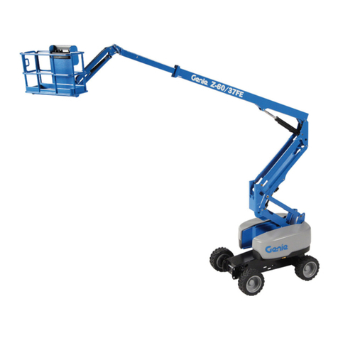
GMG 64/40 AJ-E User manual

23(5$725¶60$18$/
$-(
-DQXDU\

$-(%RRP/LIW2SHUDWRU¶V0DQXDO 3DJHL
5HYLVLRQ+LVWRU\
'DWH 8SGDWH5HDVRQ

3DJHLL
6SHFLILFDWLRQV
$-(%RRP/LIW2SHUDWRU¶V0DQXDO
Model $-($16, $-(&(
Size
Work Height 21.45m 70ft 4in 21.45m 70ft 4in
Platform
Height 19.45m 63ft 10in 19.45m 63ft 10in
Horizontal
Outreach 12.05m 39ft 6in 12.05m 39ft 6in
Up and Over
Height 8.25m 27ft 1in 8.25m 27ft 1in
Overall Length 8.72m 28ft 7in 8.72m 28ft 7in
Overall Width 2.49m 8ft 2in 2.49m 8ft 2in
Overall Height 2.52m 8ft 3in 2.52m 8ft 3in
Platform Size 1.83×0.76m/
2.44×0.91m
6ft×2ft 6in/
8ft×3ft
1.83×0.76m/
2.44×0.91m
6ft×2ft 6in/
8ft×3ft
Wheelbase 2.52 m 8ft 3in 2.52 m 8ft 3in
Ground
Clearance 0.33 m 1ft 0.33 m 1ft
Performance
Platform
Capacity 250 kg 550 lb 250 kg 550 lb
Drive Speed 6.1 km/h 3.8mph 6.1 km/h 3.8mph
Gradeability 45% 45%
Turning Radius
(Inside) 2.78 m 9ft 2.78 m 9ft
Turning Radius
(Outside) 5.49 m 18ft 5.49 m 18ft
Tail Swing 0.6 m 2ft 0.6 m 2ft
Platform
Rotation 180° 180°

3DJHLLL
6SHFLILFDWLRQV
$-(%RRP/LIW2SHUDWRU¶V0DQXDO
Model $-($16, $-(&(
Performance
Max.
Working
Slope
3°/5° 3°/5°
Turntable
Swing
400°non-continuous (standard)
360° continuous (option) 360° continuous
Max Wind
Speed 12.5 m/s 28mph 12.5 m/s 28mph
Working
Temperature -25䉝~40䉝-13~104-25䉝~40䉝-13~104
Power
Battery 24×2V/440Ah 24×2V/440Ah
Charger 48V/60A 48V/60A
Drive Motor AC 32V/3.3kw AC 32V/4.4hp AC 32V/3.3kw AC 32V/4.4hp
Lift Motor AC 32V/10kw AC 32V/13.4hp AC 32V/10kw AC 32V/13.4hp
Hydraulic
Tank
Capacity
75L 19.8 us gal 75L 19.8 us gal
Tire
Type 33×12 D610 Foam-filled tires 33×12 D610 Foam-filled tires
Weight
Gross 9200 kg 20282 lb 9200 kg 20282 lb

$-(%RRP/LIW 2SHUDWRU¶V0DQXDO 3DJHLY

$-(%RRP/LIW2SHUDWRU¶V0DQXDO
Contents
6SHFLILFDWLRQV.....................................................................................................................................LL
SECTION 1 ....................................................................................1-1
1.1 ,QWURGXFWLRQ.............................................................................................................................
1.2 6DIHW\ .............................................................................................................................
1.Intended Use..............................................................................................................................
1.Safety Alert ..................................................................................
1.Safety Operation........................................................................................................................
1..1 Operator safaty ........................................................................................................
1..2 Workplace safety .....................................................................................................
SECTION 2 MACHINE COMPONENTS AND CONTROLS .................................................
2.1 Machine Components................................................................................................................
2.2 Machine Controls and Indicators...............................................................................................
2.2.1 Ground control console ..........................................................................................
2.2.2 Ground control indicator panel ...............................................................................
2.2.3 Platform control console .........................................................................................
2.2.4 Platform control indicator panel............................................................................
SECTION 3 MACHINE INSPECTION .....................................................................................3
3.1 General ......................................................................................................................................3
3.1.1 Pre-start inspection principle...................................................................................3
3.1.2 Pre-start inspection..................................................................................................3
3.2 Function Check .........................................................................................................................3
3.2.1 Pre-start inspection principle...................................................................................3
3.2.2 Ground function check............................................................................................3
3.2.3 Platform function check ..........................................................................................3
3.3 Workplace Inspection ................................................................................................................3
3.3.1 Workplace inspection principle ...............................................................................3
3.3.2 Workplace inspection ..............................................................................................3

Contents
SECTION 4 OPERATION INSTRUCTION ..............................................................................
4.1 General ......................................................................................................................................
4.2 Machine Operation....................................................................................................................
4.2.1 Drive operation........................................................................................................
4.2.2 Platform leveling.....................................................................................................
4.2.3 Platform rotating .....................................................................................................
4.2.4 Turntable slewing ....................................................................................................
4.2.5 Raise and lowering the upper boom........................................................................
4.2.6 Telescoping the upper boom....................................................................................
4.2.7 Raising and lowering the tower boom.....................................................................
4.2.8 Raising and lowering the jib....................................................................................
4.2.9 Emergency stop.......................................................................................................
4.2.10 Manual Emergency Lowering System (GB version) ............................................
4.2.11 Auxiliary Power (CE version) ...............................................................................
4.2.12 Shut down and park...............................................................................................
4.3 Transport and Lifting.................................................................................................................4
4.3.1 Release the brake while towing...............................................................................4
4.3.2 Lifting......................................................................................................................4
4.3.3 Securing the chassis ................................................................................................4
4.3.4 Securing the platform..............................................................................................4
SECTION 5 MAINTENANCE ....................................................................................................
5.1 General ......................................................................................................................................
5.1.1 Maintenance symbols legend ..................................................................................
5.1.2 Pre-start inspection..................................................................................................
5.1.3 Maintenance hazards...............................................................................................
5.1.4 Body injury hazard..................................................................................................
5.2 Power and Hydraulic system maintenance................................................................................
5.2.1 Check hydraulic oil .................................................................................................
5.3 Battery Maintenance..................................................................................................................
5.4 Regular Maintenance.................................................................................................................
5.5 Tire and Wheel ........................................................................................................................
SECTION 6 0DFKLQH)DXOW&RGH5HIUHQFH ..............................................................
6.1 )DXOW&RGH/LVW ....................................................................................................................
$-(%RRP/LIW2SHUDWRU¶V0DQXDO
.1 Storage Conditions ....................................................................................................................
%RRP/LIW$QQXDO,QVSHFWLRQ............................................................................................................
SECTION STORAGE AND EX-FACTORY TEST ................................................................6
Section
3DJH
,QWURGXFWLRQ
This Operator’s Manual has been designed to provide you, the owner, user or operator, with the instructions and
operating procedures essential to properly and safely operate your GMG Aerial Work Platform for positioning personnel,
along with their necessary tools and materials, to overhead work locations.
7KH2SHUDWRU¶V0DQXDOPXVWEHUHDGDQGXQGHUVWRRGSULRUWRRSHUDWLQJ\RXU*0*$HULDO:RUN
3ODWIRUP7KHXVHURSHUDWRUVKRXOGQRWDFFHSWRSHUDWLQJUHVSRQVLELOLW\XQWLOKHVKHKDVUHDGDQG
XQGHUVWDQGVWKHRSHUDWRU¶VPDQXDODVZHOODVKDYLQJRSHUDWHGWKH*0*$HULDO:RUN3ODWIRUPXQGHU
VXSHUYLVLRQRIXQDXWKRUL]HGWUDLQHGDQGTXDOLILHGRSHUDWRU
,WLVHVVHQWLDOWKDWWKHRSHUDWRURIWKHDHULDOZRUNSODWIRUPLVQRWDORQHRQWKHZRUNSODFHGXULQJ
RSHUDWLRQ
0RGLILFDWLRQVRIWKLVPDFKLQHIURPWKHRULJLQDOGHVLJQDQGVSHFLILFDWLRQVZLWKRXWZULWWHQSHUPLVVLRQ
IURP*0*DUHVWULFWO\IRUELGGHQ$PRGLILFDWLRQPD\FRPSURPLVHWKHVDIHW\RIWKHPDFKLQHVXEMHFWLQJ
RSHUDWRUVWRVHULRXVLQMXU\RUGHDWK
,QWURGXFWLRQ

3DJH
$-(%RRP/LIW2SHUDWRU¶V0DQXDO
Section
*OREDO0DFKLQHU\*URXS
Global Machinery Group, Inc.
3428 Bullock Lane
San Luis Obispo, CA 93401 USA
Phone: +1.805.303.2066
www.goGMG.com
Your GMG Aerial Work Platform has been designed, built, and tested to provide safe, dependable service.
Only authorized, trained and qualified personnel shall be allowed to operate or service the machine.
GMG, as manufacturer, has no direct control over machine application and operation. Proper safety practices
are the responsibility of the owner, user and operator.
If there is a question on application and/or operation contact:
Global Machinery Group, Inc.
,QWURGXFWLRQ
,QWURGXFWLRQ

Section
3DJH
6DIHW\
'2127 RSHUDWHWKLVPDFKLQHXQWLO\RXKDYHUHDGDQGXQGHUVWRRGWKLVPDQXDOKDYHSHUIRUPHGWKH
:RUNSODFH,QVSHFWLRQ3UH6WDUW,QVSHFWLRQDQG5RXWLQH0DLQWHQDQFHDQGKDYHFRPSOHWHGDOOWKHWHVW
RSHUDWLRQVGHWDLOHGLQWKH2SHUDWLQJ,QVWUXFWLRQVVHFWLRQ
Failure to read, understand and follow all safety rules, warnings, and instructions could result in serious injury
or death. For your safety and the safety of those around you, you must operate your machine as instructed in
this manual.
GMG designs $erial :ork 3latforms to safely and reliably position personnel, along with their necessary tools
and materials, at overhead work locations. The owner/user/operator of the machine should not accept
responsibility for the operation of the machine unless properly trained.
6DIHW\$OHUW6\PEROV
GMG manuals use symbols and colors to help you recognize important safety, operation and maintenance
information:
This product can expose you to chemicals known to the State of California to cause
cancer and birth defects or other reproductive harm. For more information go to
ZZZSZDUQLQJVFDJRY
5(',QGLFDWHVDQLPPLQHQWO\KD]DUGRXVVLWXDWLRQZKLFKLIQRWDYRLGHGZLOO
UHVXOWLQGHDWKRUVHULRXVLQMXU\
25$1*(,QGLFDWHVDSRWHQWLDOO\KD]DUGRXVVLWXDWLRQZKLFKLIQRWDYRLGHG
FRXOGUHVXOWLQGHDWKRUVHULRXVLQMXU\
<(//2:ZLWKDOHUWV\PERO±,QGLFDWHVDSRWHQWLDOO\KD]DUGRXVVLWXDWLRQZKLFK
LIQRWDYRLGHGPD\UHVXOWLQPLQRURUPRGHUDWHLQMXU\
6DIHW\

Read operational
manual
Read service
manual Fire hazard No smoking Explosion hazard
Electrocution hazard Burn hazard Prohibit Step on Avoid contact Maintain required
clearance
Electrocution hazard Tip-over hazard Tip-over hazard Tip-over hazard Tip-over hazard
Wheel load Wind speed Maximum capacity Tie-down point Lanyard anchorage
points
Crushing hazard Disconnect battery Manual force Collision Hazard Maintain safety
distance
Figure 1-1 Symbol and hazard pictorials definitions
$-(%RRP/LIW 2SHUDWRU¶V0DQXDO 3DJH

Runaway hazard Fall Hazards Tire disassembly Explosion hazard
No smoking.
No flame.
Stop engine.
Stop engine. Prohibit Lifting Lifting point Avoid contact
Trained and
authorized personnel
operate the machine
only
Recovery procedure if tilt alarm sounds while
elevated
Platform uphill:
1.Lower the upper boom;
2. Lower the tower boom;
3.Retract the upper boom.
Platform downhill:
1.Retract the upper boom;
2.Lower the tower boom;
3.Lower the upper boom. Prohibit high
pressure
water-beaktest
Prohibit modify the
limit switches
Color coded direction
arrows
Collision Hazard High temperature surface Avoid contact Fill fuel oil Crushing hazard
Figure 1-1 Symbol and hazard pictorials definitions (continuous)
$-(%RRP/LIW 2SHUDWRU¶V0DQXDO 3DJH

1.Safety Operation
1..1 Operator safety
Personal Fall Protection
Personal fall protection equipment (PFPE) is required when operating this machine. If PFPE is required
in job site or in operator's manual, the following rule should be complied with:
All PFPE must comply with applicable governmental regulations, and must be inspected and used in
accordance with the PFPE manufacturer’s instructions.
1..2 Workplace safety
This machine is not electrically insulated and will not provide protection from contact with or
proximity to electrical current.
a) Obey all local and governmental regulations regarding required clearance from electrical power
lines. At a minimum, the required clearance contained in the table below must be followed. Allow
for platform movement, electrical line sway or sag, and beware of strong or gusty winds;
Table 1-1 Required clearance
No. Line Voltage Required Clearance
1 0 to 50KV 3.05 m 10ft
2 50 to 200KV 4.60 m 15ft
3 200 to 350KV 6.10 m 20ft
4 350 to 500KV 7.62 m 25ft
5 500 to 750KV 10.67m 35ft
6 750 to 1000KV 13.72m 45ft
b) Allow for platform movement, electrical line sway or sag, and beware of strong or gusty winds;
$-(%RRP/LIW2SHUDWRU¶V0DQXDO 3DJH

c) Keep away from the machine if it contacts energized power lines. Personnel on the ground or in the
platform must not touch or operate the machine until energized power lines are shut off.
Do not operate the machine during lightning or storms.
Do not use the machine as a ground for welding.
Tip-over hazard
Occupants, equipment and materials shall not exceed the maximum platform capacity.
Table 1-2 Rated load
Maximum platform capacity
Unrestricted range of motion 250 kg /550 lb
Maximum occupants 2
a) Do not exceed the maximum platform capacity;
b) Do not attach a platform rated at 250 kg /550 lb to machines with any other rated load. See the
serial label for the maximum rated capacity;
c) The weight in options and accessories (such as pipe, panel bracket and welder) will reduce rated
platform capacity and must be factored into total platform load.See the decals with the options and
accessories;
d) If using accessories, read, understand and obey the decals and instructions with the accessory;
e) Do not raise or extend the boom unless the machine is on a firm, level surface.
Do not depend on the tilt alarm as a level indicator. The tilt alarm sounds in the platform only when the
$-(%RRP/LIW2SHUDWRU¶V0DQXDO 3DJH

machine is on a severe slope.
If the tilt alarm sounds when the platform is raised, use extreme caution. Identify the condition of the
boom on the slope as shown below. Follow the steps to lower the boom before moving to a firm, level
surface. Do not rotate the boom while lowering.
a) If the tilt alarm sounds with the platform uphill:
1) Lower the upper boom;
2) Lower the tower boom;
3) Retract the upper boom.
b) If the tilt alarm sounds with the platform downhill:
1) Retract the upper boom;
2) Lower the tower boom;
3) Lower the upper boom.
Do not raise the boom when wind speeds may exceed 12.5 m/s (28mph).
If wind speeds exceed 12.5 m/s (28mph) when the boom is raised, lower the boom and do not continue
to operate the machine. Do not operate the machine in strong or gusty winds. Do not increase the
surface area of the platform or the load. Increasing the area exposed to the wind will decrease machine
stability.
Table 1-3 Beaufort scale
Beaufort scale Wind speed Instruction
0 0 -0.2 m/s 0 -0.45mph Calm
1 0.3 -1.5 m/s 0.67 -3.36mph Light air
2 1.6 -3.3 m/s 3.58 -7.38mph Light breeze
3 3.4 -5.4 m/s 7.61 -12.08mph Gentle breeze
4 5.5 -7.9 m/s 12.30 -17.67mph Moderate breeze
5 8.0 -10.7 m/s 17.90 -23.94mph Fresh breeze
6 10.8 -13.8 m/s 24.16 -30.87mph Strong breeze
7 13.9 -17.1 m/s 31.09 -38.25mph Moderate gale
8 17.2 -20.7 m/s 38.48 -46.30mph Fresh gale
9 20.8 -24.4 m/s 46.53 -54.58mph Strong gale
$-(%RRP/LIW2SHUDWRU¶V0DQXDO 3DJH

a) Use extreme care and slow speeds while driving the machine in the stowed position across uneven
terrain, debris, unstable or slippery surfaces and near holes and drop-offs;
b) Do not drive the machine on or near uneven terrain, unstable surfaces or other hazardous
conditions with the boom raised or extended;
c) Never attempt to use the machine as a crane;
d) Do not push the machine or other objects with the boom;
e) Do not contact adjacent structures with the boom;
f) Do not tie the boom or platform to adjacent structures;
g) Do not place loads outside the platform perimeter;
h) Do not alter or disable machine components that in any way affect safety and stability;
i) Do not replace items critical to machine stability with items of different weight or specification;
j) Do not replace factory-installed tires with tires of different specification or ply rating;
k) Do not use air-filled tires. These machines are equipped with foam-filled tires. Wheel weight is
critical to stability;
l) Do not use the platform controls to free a platform that is caught, snagged, or otherwise prevented
from normal motion by an adjacent structure. All personnel must be removed from the platform
before attempting to free the platform using the ground controls;
m) Do not modify or alter an aerial work platform without prior written permission from the
manufacture. Mounting attachments for holding tools or other materials onto the platform, toe
boards, or guard rail system can increase the weight in the platform and the surface area of the
platform or the load;
n) Do not push off or pull toward any object outside of the platform.
$-(%RRP/LIW2SHUDWRU¶V0DQXDO 3DJH

Tip-over hazard
Manual force cannot be greater than specification when operating, otherwise may cause tipping over.
Table 1-4 Maximum allowable manual force
Model Manual force Maximum occupants
$-( 400N /90 lbs force 2
a) Do not place or attach fixed or overhanging loads to any part of this machine;
b) Do not place ladders or scaffolds in the platform or against any part of this machine;
c) Do not transport tools and materials unless they are evenly distributed and can be safely handled by
person(s) in the platform;
d) Do not use the machine on a moving or mobile surface or vehicle;
e) Be sure the tires are in good condition and the lug nuts tightened, besides the tightening torque
should be 300N/m(20.2 lb/ft);
f) Do not drive the machine on a slope that exceeds the maximum uphill, downhill or side slope
rating of the machine. Slope rating applies only to machines in the stowed position.
Table 1-5 Maximum slope rating, stowed position
Maximum slope rating, stowed position
Platform uphill 45% (24°)
Platform downhill 45% (14°)
Side slope 25% (14°)
Note: slope rating is subject to ground conditions with one person in the platform and adequate
traction. Additional platform weight may reduce slope rating.
$-(%RRP/LIW2SHUDWRU¶V0DQXDO 3DJH

Fall Hazards
a) Occupants must wear a safety belt or harness in accordance with governmental regulations. Attach
the lanyard to the anchor provided in the platform;
b) Do not sit, stand or climb on the platform guard rails. Maintain a firm footing on the platform floor
at all times;
c) Do not climb down from the platform when raised;
d) Keep the platform floor clear of debris. Use extreme care while entering or exiting the platform. Do
not enter or exit the platform unless the machine is in the stowed position. Enter or exit the platform
through the gate only. Face the machine and ensure "three-point contact" with the machine (two
hands and one foot, or two feet and one hand) while entering or exiting the platform.
$-(%RRP/LIW2SHUDWRU¶V0DQXDO 3DJH

Collision Hazard
a) Be aware of limited sight distance and blind spots when driving and operating;
b) Check the work area for overhead obstructions or other possible hazards;
c) Be aware of crushing hazards when grasping the platform guard rail;
d) Be aware of the boom position and tail swing when rotating the turntable;
e) Operators must comply with employer, job site, and governmental rules regarding use of personal
protective equipment.
$-(%RRP/LIW2SHUDWRU¶V0DQXDO 3DJH

Do not lower the boom unless the area below is clear of personnel and obstructions.
Limit travel speed according to the condition of the ground surface, congestion, slope, location of
personnel, and any other factors which may cause collision.
Observe and use the color-coded direction arrows on the platform controls and drive chassis for drive
and steer functions.
Do not operate a boom in the path of any crane unless the controls of the crane have been locked out
and/or precautions have been taken to prevent any potential collision.
No stunt driving or horseplay while operating a machine.
Body Injury Hazard
a) Do not operate a machine with a hydraulic oil or air leak. An air leak or hydraulic leak can
penetrate and/or burn skin;
b) Improper contact with components under any cover will cause serious injury. Only trained
maintenance personnel should access compartments.
Suggestion: access by the operator is only advised when performing a pre-operation inspection. All
compartments must remain closed and secured during operation.
$-(%RRP/LIW2SHUDWRU¶V0DQXDO 3DJH
Table of contents
Popular Boom Lift manuals by other brands

Haulotte
Haulotte OPTIMUM 1931 E Operator's manual

Mec
Mec Speed Level Series Service & parts manual

Haulotte Group
Haulotte Group H14T Operating and maintenance instructions

Mec
Mec 45-J Diesel Service & parts manual

JLG
JLG Lull 1044C-54 II Series Service manual

Oshkosh
Oshkosh JLG 1850SJ Operation and safety manual