6 GenieZ-80/60 PartNo.82258
Operator's Manual First Edition · Fifth Printing
SAFETY RULES
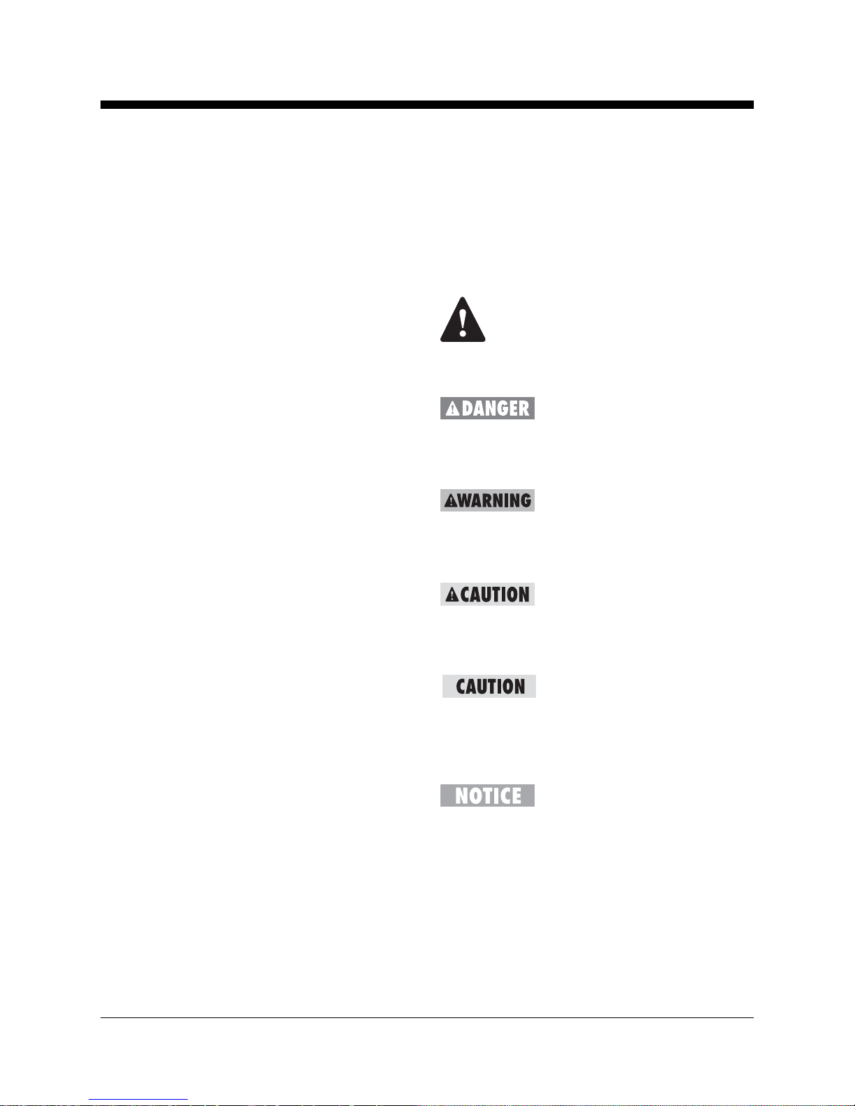
Decal Legend
Genie product decals use symbols, color coding
and signal words to identify the following:
Safety alert symbol—used to alert
personneltopotentialpersonal
injury hazards. Obey all safety
messages that follow this symbol
to avoid possible injury or death.
Red—usedtoindicatethe
presence of an imminently
hazardous situation which, if not
avoided, will result in death or
seriousinjury.
Orange—usedtoindicatethe
presence of a potentially
hazardous situation which, if not
avoided, could result in death or
seriousinjury.
Yellow with safety alert symbol—
used to indicate the presence of a
potentiallyhazardoussituation
which, if not avoided, may cause
minorormoderateinjury.
Yellow without safety alert
symbol—used to indicate the
presence of a potentially
hazardous situation which, if not
avoided, may result in property
damage.
Green—usedtoindicateoperation
ormaintenanceinformation.
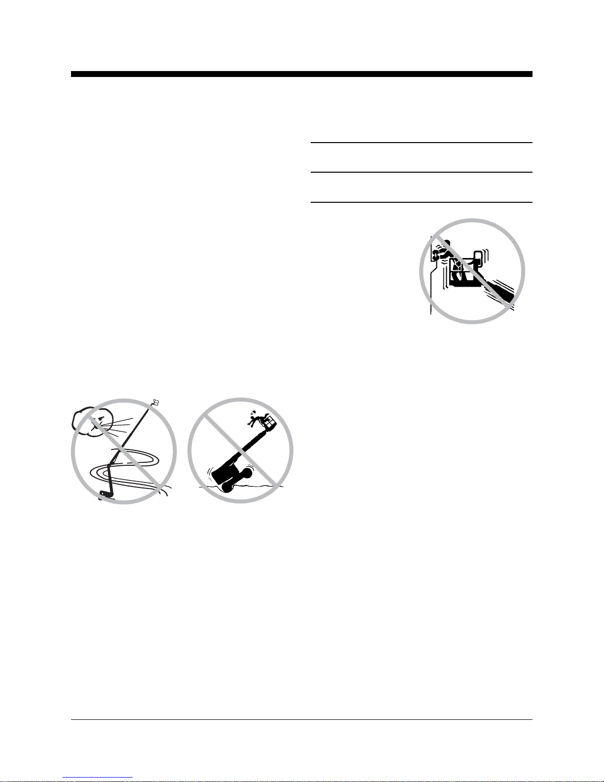
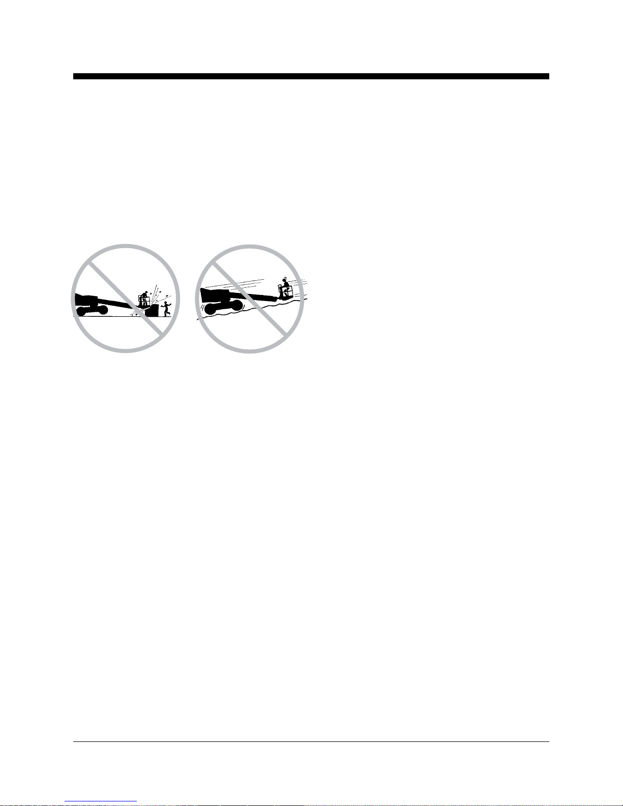
Damaged Machine Hazards
Donot usea damaged ormalfunctioning machine.
Conductathoroughpre-operationinspectionofthe
machine and test all functions before each work
shift. Immediately tag and remove from service a
damaged or malfunctioning machine.
Be sure all maintenance has been performed as
specified in this manual and the appropriate
service manual.
Be sure all decals are in place and legible.
Be sure that the operator’s, safety and
responsibilitiesmanualsarecomplete,legible and
in the storage container located in the platform.
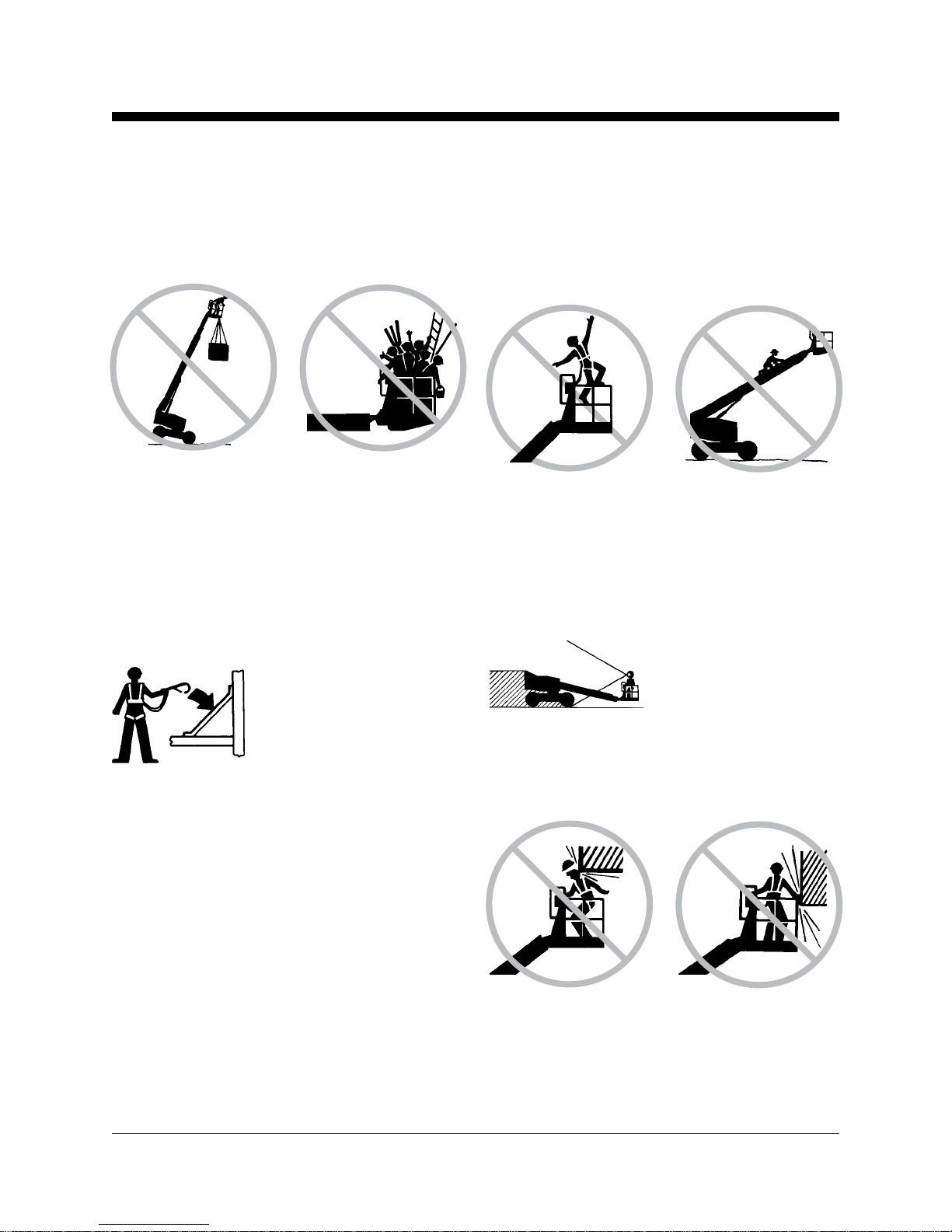
Bodily Injury Hazard
Do not operate the machine with a hydraulic oil or
air leak. An air leak or hydraulic leak can penetrate
and/or burn skin.
Always operate the machine in a well-ventilated
area to avoid carbon monoxide poisoning.