GMMC MIFARE SAM AV3 User manual

User Manual
MIFARE SAM AV3 Evaluation Board
User manual COMPANY PUBLIC
Information provided in this document is subject to legal disclaimers
© GMMC GmbH. 2020. All rights reserved.
Rev. 1.0 19-JAN-2022
1
Document information
Information
Content
Keywords
MIFARE SAM AV3, evaluation board, Direct Mode (X-mode), Satellite Mode (S-mode), I²C, SPI,
ISO/IEC 7816, CLRC663 family, MCU, Arduino
Abstract
This manual shows how to operate the MIFARE SAM AV3 Evaluation board
Revision history
Rev
Date
Description
1.0
2022- 01-19
Initial version

User Manual
MIFARE SAM AV3 Evaluation Board
User manual COMPANY PUBLIC
Information provided in this document is subject to legal disclaimers
© GMMC GmbH. 2020. All rights reserved.
Rev. 1.0 19-JAN-2022
2
1 Introduction
The MIFARE SAM AV3 Arduino shield shaped evaluation board is designed to help
evaluate the features and of the MIFARE SAM AV3 IC in combination with any MCU and
to quickly and easy development secure contactless tag applications.
The evaluation board therefore incorporates a 13.56 MHz NFC frontend IC of the
CLRC663 plus family and an embedded inductive loop antenna..
Scope
The scope of this document is to give an overview of available interfacing options and
usage possibilities of the MIFARE SAM AV3 evaluation board.
Abbreviations
Table 1. Abbreviations
I²C
Inter-Integrated Circuit
MCU
Microcontroller Unit
NFC
Near Field Communication
PCB
Printed-Circuit Board
SAM
Secure Access Module
SPI
Serial Peripheral Interface
USB
Universal Serial Bus

User Manual
MIFARE SAM AV3 Evaluation Board
User manual COMPANY PUBLIC
Information provided in this document is subject to legal disclaimers
© GMMC GmbH. 2020. All rights reserved.
Rev. 1.0 19-JAN-2022
3
2 Compliance Statements
FCC Compliance Statement
This device complies with part 15 of the FCC Rules. Operation is subject to the following two conditions:
(1) this device may not cause harmful interference, and (2) this device must accept any interference received, including
interference that may cause undesired operation.
CAUTION: The grantee is not responsible for any changes or modifications not expressly approved by the party
responsible for compliance. Such modifications could void the user’s authority to operate the equipment.
NOTE: This equipment has been tested and found to comply with the limits for a Class B digital device, pursuant to Part
15 of the FCC Rules. These limits are designed to provide reasonable protection against harmful interference in a
residential installation. This equipment generates, uses, and can radiate radio frequency energy, and if not installed and
used in accordance with the instructions, may cause harmful interference to radio communications. However, there is no
guarantee that interference will not occur in a particular installation. If this equipment does cause harmful interference to
radio or television reception, which can be determined by turning the equipment off and on, the user is encouraged to try
to correct the interference by one or more of the following measures:
–Reorient or relocate the receiving antenna.
–Increase the separation between the equipment and receiver.
–Connect the equipment into an outlet on a circuit different from that to which the receiver is connected.
–Consult the dealer or an experienced radio/TV technician for help.
Canadian Compliance Statement
This device contains license-exempt transmitter(s)/receiver(s) that comply with Innovation, Science and Economic
Development Canada license-exempt RSS(s). Operation is subject to the following two conditions:
(1) This device may not cause interference.
(2) This device must accept any interference, including interference that may cause undesired operation of the device.
L'émetteur/récepteur exempt de licence contenu dans le present appareil est conformeaux CNR d'Innovation, Sciences
et Développement économique Canada applicables aux appareils radio exempts de licence. L'exploitation est autorisée
aux deux conditions suivantes :
1) L'appareil ne doit pas produire de brouillage;
2) L'appareil doit accepter tout brouillage radioélectrique subi, mêmesi le brouillage est susceptible d'en compromettre le
fonctionnement.
CE Declaration of Conformity
The technical documentation required to demonstrate that the products meet the requirements of the relevant directives
has been compiled and is available for inspection by the relevant enforcement authorities.
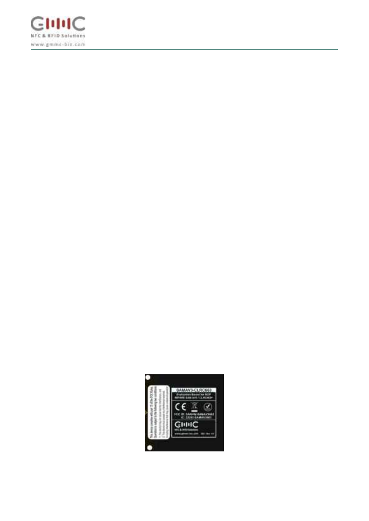
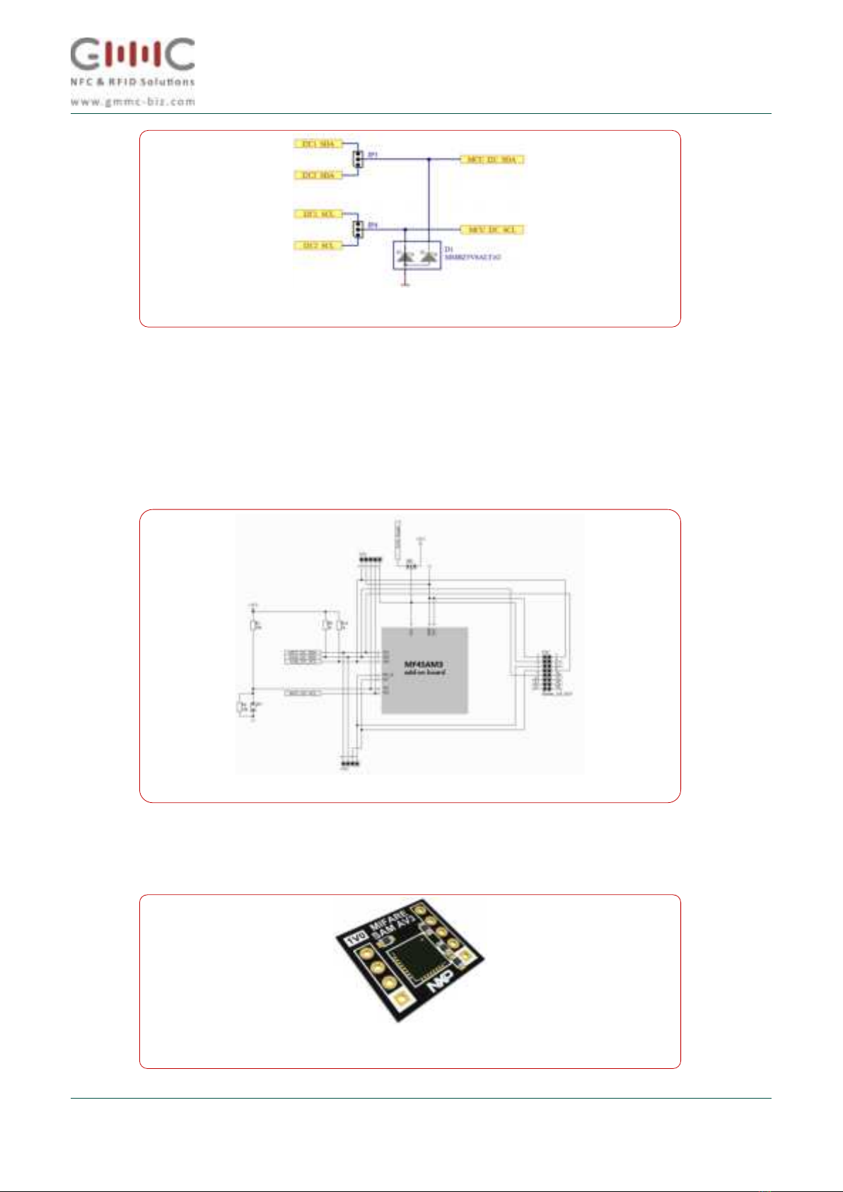
Label location and information
The necessary compliance information label can be found at the bottom of the PCB. There are to possible
options. Silk screen and label or silk screen only.
Figure 1 Label location

User Manual
MIFARE SAM AV3 Evaluation Board
User manual COMPANY PUBLIC
Information provided in this document is subject to legal disclaimers
© GMMC GmbH. 2020. All rights reserved.
Rev. 1.0 19-JAN-2022
4
3 Block Diagram
Figure 2: MIFARE SAM AV3 evaluation board Block Diagram
Figure 3:Building Blocks and connectors
Figure 4: typical development setup

User Manual
MIFARE SAM AV3 Evaluation Board
User manual COMPANY PUBLIC
Information provided in this document is subject to legal disclaimers
© GMMC GmbH. 2020. All rights reserved.
Rev. 1.0 19-JAN-2022
5
Arduino® R3 header
The MIFARE SAM AV3 evaluation board is equipped with a Arduino® R3 compatible header. The
evaluation board can be fully powered with the 5 V line from this header. 3V3 is directly generated on
board out of this 5 V line. The header also uses the SPI interface, which can be connected to the
CLRC663 host interface fordirect communication. For SAM communication, the user can choose
between 2 I²C interfaces: The default one on IOH1 (called I²C1), as well as an alternative pinning on
AD1 (called I²C2). IO4 and IO5 are used for the CLRC663 PDOWN and IRQ, and IO6 can be
jumpered to provide the MIFARE SAM AV3 VDD.
4 Schematics
Power management
The MIFARE SAM AV3 evaluation board is equipped with a mini-USB connector to power the
system. The port is used only to provide for power only.The entire board can be powered by either
the USB port or the 5 V line on the Arduino header. The power LED signalizes 3.3V power
availability.
Figure 5: Arduino header pin assignment
Figure 6: Power Management

User Manual
MIFARE SAM AV3 Evaluation Board
User manual COMPANY PUBLIC
Information provided in this document is subject to legal disclaimers
© GMMC GmbH. 2020. All rights reserved.
Rev. 1.0 19-JAN-2022
6
CLRC663
The MIFARE SAM AV3 evaluation board also has a CLRC663 contactless frontend incorporated
on the PCB. The digital communication interface (SPI, and I²C ) from MCU to the CLRC663 can
be selected via jumpers. The SPI-Interface is directly connected to the Arduino® header, the I²C
interfaces are meant to be used by the MIFARE SAM AV3 for its X-mode. Jumper setting details
can be found in the section jumper settings in this document
Figure 7: CLRC663 communication interface selection
Figure 8: Antenna matching circuit

User Manual
MIFARE SAM AV3 Evaluation Board
User manual COMPANY PUBLIC
Information provided in this document is subject to legal disclaimers
© GMMC GmbH. 2020. All rights reserved.
Rev. 1.0 19-JAN-2022
7
5 MIFARE SAM AV3 –Add-on Board
Add-on board
The MIFARE SAM AV3 itself is placed on an add-on board, to be able to easily exchange the MIFARE
SAM AV3 in case it has been misconfigured. The pullups for theMCU_I²C_xxx interface, as well as the
voltage level divider are placed on the add-on board.
The MIFARE SAM AV3 can be accessed by either its I²C_Slave (MCU_I²C_xxx) interface from the host
MCU, or the ISO7816 interface via CN5. This header is pin compatible to the GMMC ISO7816 to SIM SAM
Smart Card adapter.
Figure 9: I²C Interface selection with protection
Figure 10: MIFARE SAM AV3 Add-on board
Figure 11: related product MIFARE SAM AV3 Add-on board

User Manual
MIFARE SAM AV3 Evaluation Board
User manual COMPANY PUBLIC
Information provided in this document is subject to legal disclaimers
© GMMC GmbH. 2020. All rights reserved.
Rev. 1.0 19-JAN-2022
8
6 MIFARE SAM Evaluation Board - Jumper Setting
The MIFARE SAM AV3 evaluation board comes with 3 different colors of Jumpers:
•GREEN:Configuration of RC663 interfaces
•YELLOW: MCU board I²C interface selection
•RED:MIFARE SAM AV3 configuration
CLRC663 Interface Mode
The CLRC663 NFC reader frontend IC offers a Host and a SAM interface.
The HOST communication interface can be configured to SPI or I²C by configuring the CLRC663
IFSEL 0/1 pins via jumper settings as shown in below.
Figure 12: MIFARE SAM AV3 Jumper options
Figure 13: Jumper locations for Host interface selection

User Manual
MIFARE SAM AV3 Evaluation Board
User manual COMPANY PUBLIC
Information provided in this document is subject to legal disclaimers
© GMMC GmbH. 2020. All rights reserved.
Rev. 1.0 19-JAN-2022
9
SPI
For SPI communication between MCU and CLRC663 the 4 jumpers on the 10 pin header need to be
positioned as shown. This setting is intended to use the MIFARE SAM AV3 in S-mode, or in an S/X
mixed mode. At this point, the MCU can already control the CLRC663 via SPI.
6.1.1 I²C
In case I²C is selected, the CLRC663 will be controlled by the MIFARE SAM AV3 in X- mode. The 4
jumpers need to be inserted in the 10 pin header as shown, these correspond to the ADR0 and ADR1 pins
on the CLRC663 host interface in I²C configuration.
Now the host interface of the CLRC663 is configured as I²C and both ADR pins are pulled to low. The
MIFARE SAM AV3 Master I²C interface (SAM_I²C_xxx) can be routed to the host interface of the
CLRC663. This is done with JP1 and JP2.
6.1.2 CLRC663 SAM I²C Interface
The CLRC663 SAM interface is a dedicated second interface for MIFARE SAM X-mode operation. As this
interface is switched off per default, the I²C signal from the MIFARE SAM AV3 needs to be set routed to
interface 2 on JP1 and JP2.
If this interface is already activated by setting the corresponding bits in the HostCtl register of the
CLRC663, the above setting is sufficient to communicate between CLRC663 and the MIFARE SAM AV3.
If not, then an additional SPI connection for the MCU to the CLRC663 is needed, to activate the SAM
interface.
Figure 14: Jumper settings SPI or I²C Host interface mode
Figure 15: Selection of CLRC663 SAM interface

User Manual
MIFARE SAM AV3 Evaluation Board
User manual COMPANY PUBLIC
Information provided in this document is subject to legal disclaimers
© GMMC GmbH. 2020. All rights reserved.
Rev. 1.0 19-JAN-2022
10
MCU Interface Selection
The connection between the MIFARE SAM AV3 and the MCU is done by either of the 2 supported I²C
interface locations on the Arduino® R3 header. The selection is done by JP3 and JP4, which are placed on
the corresponding pins.
MIFARE SAM AV3 host interface and VDD selection
The MIFARE SAM AV3 evaluation board offers two options to interface with the MIFARE SAM AV3:
I²C and ISO7816. I²C was explained earlier in this document. For ISO7816 communication to supply and
configure VDD of the MIFARE SAM AV3.
VDD is selected on JP9, the options are permanent 3V3 or IO6 on the Arduino header. Permanent 3V3
means that the MIFARE SAM AV3 will stay in the state it is, until the whole board is power cycled. The ATR
of the SAM only needs to be retrieved once. Using IO6 as VDD gives the user the possibility to only power
cycle the MIFARE SAM AV3, therefore having the option of a reset, without resetting the MCU.
In case a user wants to access the MIFARE SAM AV3 via the ISO7816 Smartcard interface, a Jumper needs
to be placed on the ISO7816 header as shown and it is important that in this case, the VDD selection jumper
needs to be removed (set to inactive position as shown), as the MIFARE SAM AV3 VDD needs to be
controlled by the ISO7816 interface.
Figure 16: SAM AV3 VDD and ISO7816 selection

User Manual
MIFARE SAM AV3 Evaluation Board
User manual COMPANY PUBLIC
Information provided in this document is subject to legal disclaimers
© GMMC GmbH. 2020. All rights reserved.
Rev. 1.0 19-JAN-2022
11
7 MIFARE SAM AV3 –required default configuration changes
To ensure backwards compatibility to the SAM AV2 the default configuration is set for the NXP frontend
reader PN523 IC for X-mode communication. Along with this, the I²C processing clock speed needs to be
adjusted as well as this is set to I²C fast mode (12 MHz processing clock speed) and needs to be reduced
for operating the CLRC663.
This needs to be changed using the SAM SetConfig command once. The command looks like the following:
Command: 80 3C 01 00 01 03
Set Configuration for reader frontend selection
Byte
Value
Meaning
CLA
0x80
Class
INS
0x3C
Instruction: SAM SetConfiguration
P1
0x01
Reader IC configuration
P2
0x00
RFU
Le
0x01
Length of subsequent data field
INF
0x03
X-mode frontend CLRC663
Command: 80 3C 02 00 01 06
SAM_SetConfiguration for I²C processing clock speed
Byte
Value
Meaning
CLA
0x80
Class
INS
0x3C
Instruction: SAM SetConfiguration
P1
0x02
I²C processing clock speed
P2
0x00
RFU
Le
0x01
Length of subsequent data field
INF
0x06
I²C processing clock speed: 6 MHz
This reduces the I²C communication speed on the X-mode interface to ~400 kbit/s.
All details about the MIFARE SAM AV3 configuration and features can be found in the respective NXP
documents.

User Manual
MIFARE SAM AV3 Evaluation Board
User manual COMPANY PUBLIC
Information provided in this document is subject to legal disclaimers
© GMMC GmbH. 2020. All rights reserved.
Rev. 1.0 19-JAN-2022
12
8 Modes of Operation
X-Mode
The easiest way to get started with the MIFARE SAM AV3 evaluation board is to operate the
MIFARE SAM AV3 in X-mode. See an example configuration below where the SAM can be accessed via
the I²C1 interface from the MCU, and will communicate to the CLRC663 via its host interface,configured as
I²C. The SAM VDD in below example is connected to IO6.
S-Mode
In this S-mode configuration, the MIFARE SAM AV3 is not connected to the CLRC663.The host MCU
controls the CLRC663 via the SPI interface, and the MIFARE SAM AV3 via I²C1.
Figure 17: X-mode configuration example
Figure 18: S-mode configuration example

User Manual
MIFARE SAM AV3 Evaluation Board
User manual COMPANY PUBLIC
Information provided in this document is subject to legal disclaimers
© GMMC GmbH. 2020. All rights reserved.
Rev. 1.0 15-01-2022
13
XS - Mode
In this configuration, the CLRC663 is connected on its host interface via SPI to the MCU,and
on the second interface via I²C to the SAM. The MIFARE SAM AV3 is connected via I²C1 to
the MCU. In this way, the MCU can control the CLRC663's LPCD procedure, and if a card is
detected, the SAM can be switched on and take over the control over the CLRC663.
ISO7816 Interface
In this configuration, the MIFARE SAM AV3 is controlled via the ISO7816 Interface which is
available on the 16-pin header CN5. The pinning is compatible to the GMMC ISO7816 to
SIM SAM Adapter which also can be used stand-alone in case the SIM sized SAM is used.
Figure 19: XS-mode configuration
Figure 20: ISO7816 Mode

User Manual
MIFARE SAM AV3 Evaluation Board
User manual COMPANY PUBLIC
Information provided in this document is subject to legal disclaimers
© GMMC GmbH. 2020. All rights reserved.
Rev. 1.0 15-01-2022
14
Table of Figures
Figure 1 Building Blocks and power supply _______________________________________________________ 3
Figure 2: MIFARE SAM AV3 evaluation board Block Diagram _________________________________________ 4
Figure 3 Building Blocks and connectors _________________________________________________________ 4
Figure 4 typical development setup _____________________________________________________________ 4
Figure 5: Arduino header pin assignment _________________________________________________________ 4
Figure 6: Power Management __________________________________________________________________ 4
Figure 7: CLRC663 communication interface selection_______________________________________________ 4
Figure 8: Antenna matching circuit ______________________________________________________________ 4
Figure 9: I²C Interface selection with protection____________________________________________________ 4
Figure 10: MIFARE SAM AV3 Add-on board _______________________________________________________ 4
Figure 11: related product MIFARE SAM AV3 Add-on board __________________________________________ 4
Figure 12: MIFARE SAM AV3 Jumper options ______________________________________________________ 4
Figure 13: Jumper locations for Host interface selection _____________________________________________ 4
Figure 14: Jumper settings SPI or I²C Host interface mode____________________________________________ 4
Figure 15 Selection of CLRC663 SAM interface _____________________________________________________ 4
Figure 16 SAM AV3 VDD and ISO7816 selection____________________________________________________ 4
Figure 17: X-mode configuration example ________________________________________________________ 4
Figure 18: S-mode configuration example ________________________________________________________ 4
Figure 19: XS-mode configuration _______________________________________________________________ 4
Figure 20: ISO7816 Mode _____________________________________________________________________ 4
Figure 21: related product ISO7816 ID1 to SIM-SAM Adapter ________________________________________ 4
Figure 21: related product
ISO7816 ID1 to SIM-SAM Adapter

User Manual
MIFARE SAM AV3 Evaluation Board
User manual COMPANY PUBLIC
Information provided in this document is subject to legal disclaimers
© GMMC GmbH. 2020. All rights reserved.
Rev. 1.0 15-01-2022
15
Document References
1. Data sheet –MIFARE SAM AV3, document number DS3235xx via NXP DocStore.
2. Application Notes –please visit NXP.com
The document content may see additions and modifications in future releases. GMMC GmbH does not give any
representations or warranties as to the accuracy or completeness of information included herein and shall have
no liability for the consequences of use of such information.
Notice: All referenced brands, product names, service names and trademarks are the property of their respective
owners.
© GMMC GmbH 2022 All rights reserved.
For more information, about MIFARE SAM AV3 please visit: http://www.nxp.com
For more information, about GMMC GmbH products and services visit http://www.gmmc-biz.com
Date of release: 17 January 2022
Table of contents