GMT GMT 050 User manual

USER MANUAL GMT 050
FELLING GRAPPLE (including GMT050 TTC)
Serial number: 255 and up (release date: Oct-2020)

GMT 050 User manual
2
Contents
1. General ............................................................................................................................................................ 3
1.1 Use of this manual .................................................................................................................................. 3
1.2 Warnings and warning pictograms ......................................................................................................... 3
2. Safety guidelines ............................................................................................................................................. 4
3. Serial plate / Carrying vehicle .......................................................................................................................... 6
3.1 Serial plate .............................................................................................................................................. 6
3.2 Carrying vehicle ...................................................................................................................................... 6
4. Preparation for use ......................................................................................................................................... 7
4.1 Transport ................................................................................................................................................ 7
4.2 Mounting the felling grapple .................................................................................................................. 8
4.3 Connecting the GMT050 TTC .................................................................................................................. 9
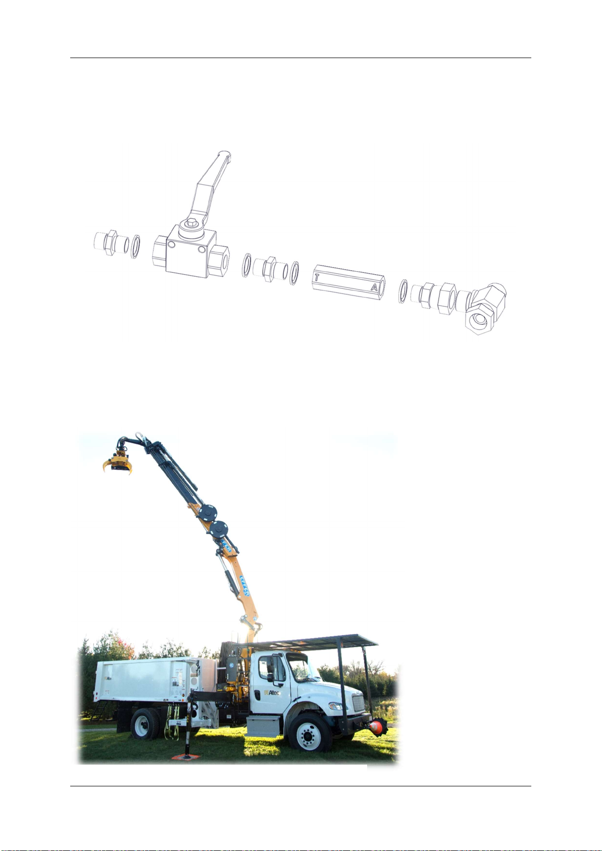
4.4 Installing the drain valve....................................................................................................................... 10
4.5 Installation on Telehandler ................................................................................................................... 11
4.6 Operating pressure ............................................................................................................................... 12
4.6.1 Hydraulic schematic for mounting ............................................................................................... 12
4.6.2 Hydraulic schematic for mounting GMT050 TTC ......................................................................... 13
4.6.3 Hydraulic schematic ..................................................................................................................... 14
5. Application .................................................................................................................................................... 15
5.1 Application GMT050 ............................................................................................................................. 15
5.2 Application GMT050 TTC ...................................................................................................................... 16
5.3 Operation of the felling grapple ........................................................................................................... 17
5.3.1 Felling a tree or branch ................................................................................................................ 18
5.3.2 Felling a tree or branch with TTC ................................................................................................. 20
5.4 Supplied tools ....................................................................................................................................... 22
4.3 Lifting reference for sawing at height .................................................................................................. 22
6. Maintenance ................................................................................................................................................. 24
6.1 Safety recommendations ..................................................................................................................... 24
6.2 Daily maintenance ................................................................................................................................ 24
6.3 Maintenance schedule ......................................................................................................................... 25
6.4 Repairs / Welding ................................................................................................................................. 25
6.5 Replacement of saw bar and chain ...................................................................................................... 26
6.6 Lubricants ............................................................................................................................................. 27
6.7 Hydraulic fluid ....................................................................................................................................... 28
6.8 Chain oil ................................................................................................................................................ 28
6.9 Handle the chainsaw ............................................................................................................................ 29
7. Adjusting the felling grapple ......................................................................................................................... 30
7.1 Pressure adjustments ........................................................................................................................... 30
7.1.1 Adjusting the valve block ............................................................................................................. 30
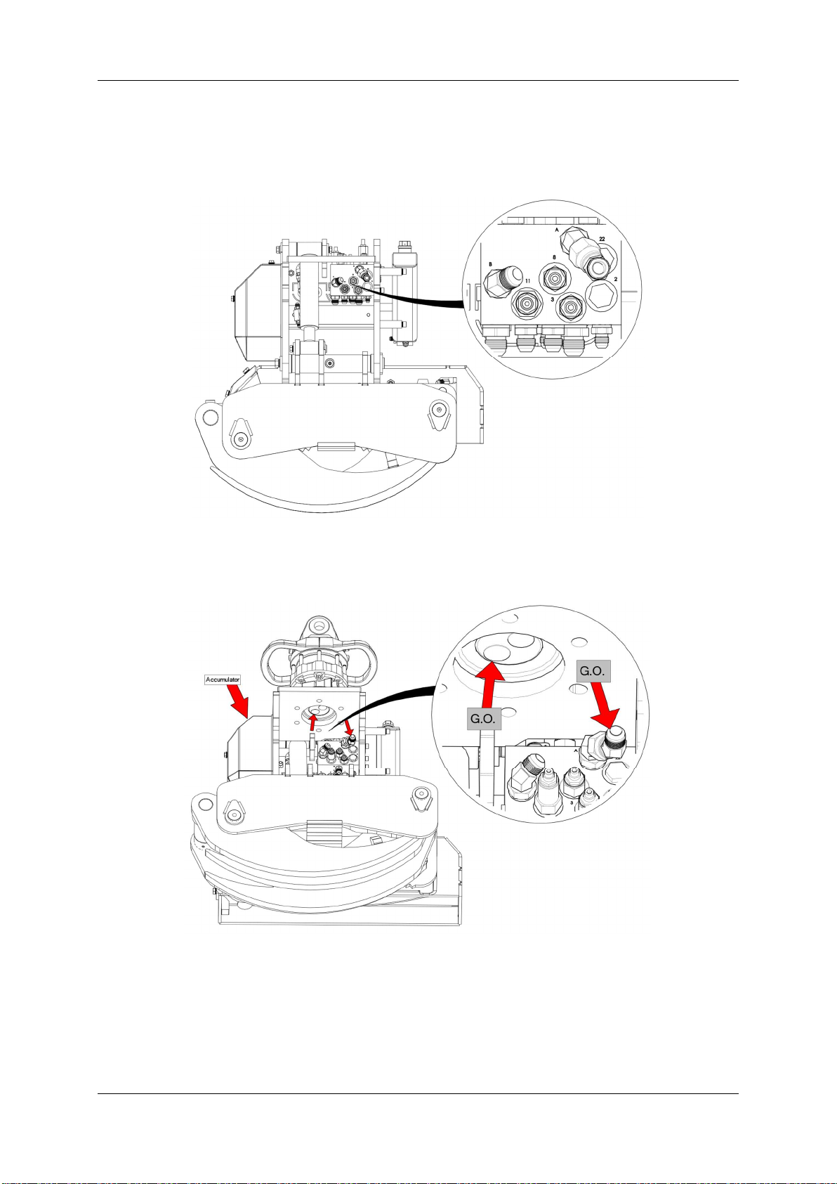
7.1.2 Pressurizing the accumulator ...................................................................................................... 35
7.1.3 Saw blade speed .......................................................................................................................... 37
7.1.4 Braking force of the TTC .............................................................................................................. 37
7.2 Saw safety guidelines ........................................................................................................................... 38
8. Removal of grapple ....................................................................................................................................... 38
9. Troubleshooting guide .................................................................................................................................. 39
9.1 General ................................................................................................................................................. 39
9.2 Checklist................................................................................................................................................ 39
9.3 Common malfunctions ......................................................................................................................... 39
9.3.1 Sawing problems .......................................................................................................................... 39
9.3.2 Problems with tilt up, placing grapple in horizontal position ...................................................... 40
9.3.3 Problems with tilt down, placing grapple in default position ...................................................... 40
10. Technical specifications ................................................................................................................................. 41
10.1 GMT050 ................................................................................................................................................ 41
10.2 GMT050 TTC ......................................................................................................................................... 42

GMT 050 User manual
3
1. General
1.1 Use of this manual
This user manual has been compiled for persons who have previous practical experience in the use of
(forestry) machinery. Applying common sense and skills will supplement the use of this user manual.
Warning pictograms provide highly important information about
safety risks. The dangers posed by various situations can result in
incapacitation or fatality.
Attention pictograms indicate that products, processes or the
environment can be affected.
All descriptions, instructions and technical details contained in this user manual are based on the most
up-to-date information available on the felling grapple.
This product is constantly being further developed, and the manufacturer therefore reserves the right
to modify the product without prior notice.
Felling grapple malfunctions can often be resolved by carefully reading the user manual. If recovery or
repair is not possible, you must contact the manufacturer or distributor.
1.2 Warnings and warning pictograms
Warnings and warning pictograms have been added to certain components.
These texts and pictograms must be noted in order to prevent injury to persons
and damage to the felling grapple.
This pictogram indicates to the user that mounting, maintenance and repairs to
and of the felling grapple can be aided by thoroughly reading the user manual
and by relying on the information it contains.
If the felling grapple is to be used by multiple persons, the owner must order all
users to work strictly according to the user manual.
Warnings such as ‘’safe distance’’.
The safety distance is set for at least 1 ½ the length of the tree.
Within this safety zone no other persons are allowed.
The operator should be in the area of the escape route.
The escape route is at a 45-degree opposite of the felling direction.
Be sure the escape route is clear of obstacles or hazards.
Often the “safe distance” is referred to 50 meters (165 feet) safety zone.
Tree
Direction
of fall
Escape
route
Escape
route
Danger
area

GMT 050 User manual
4
2. Safety guidelines
These safety regulations cannot eliminate all hazardous situations
and accidents related to use of the felling grapple. However, they
will be as effective as possible in preventing potential hazardous
situations and accidents.
Legal regulations must also be observed in addition to the details and instructions provided here.
Wear appropriate clothing to prevent being trapped by the machinery.
Use PPE such as safety gloves, safety glasses, a safety helmet and hearing protection.
Be aware of the risk of losing your footing when working on/with the felling grapple.
Beware of telephone and electricity cables when working near telephone and high-voltage pylons.
Keep a safe distance and do not endanger any persons. If you are not confident about the situation,
contact the local electricity operator. If you are forced to abandon the equipment, your own safety is
imperative. Do not pause to secure the machinery.
Leave the scene of potential electrical danger as quickly as possible. Never run, but move forward by
pressing your legs together and walking away.
Make sure that no persons, animals and/or goods are within the 50-meter safety zone (165 feet) while
the machine is in use.
Various weather conditions can affect use of the felling grapple. Such conditions include wind, snow
and/or storms. Weather conditions must be taken into account before use of the felling grapple.
Weather circumstances at the site allow use of the felling grapple must also be determined. If this
proves to not be the case, appropriate precautions must be taken
Familiarize yourself with the felling grapple before use. Knowledge about (energy) wood felling and
tree maintenance is also preferred.
Observe all instructions contained in the user manual of the felling grapple, the crane and the carrying
vehicle in order to prevent hazardous situations and avoid endangering any persons.
The felling grapple may only be used once all safety regulations have been thoroughly read and all
components have been correctly attached/installed.
The carrying vehicle must be turned off during mounting of the felling grapple. Make sure that the
system is depressurized, or depressurize it by moving the joystick or handle. This is essential to ensure
that work is carried out safely.
The carrying vehicle with the felling grapple may in no way whatsoever be operated or repaired if the
operator is under the influence of alcohol and/or narcotics.
An ability to work precisely is required in order to measure pressures and to set/adjust the felling
grapple.
A rise in pressure inside/on the system can result in damage to the felling grapple and can increase the
risk of accidents!

GMT 050 User manual
5
Rest the felling grapple on a firm surface when work is complete or when temporarily turning off the
carrying vehicle.
Standing under a ‘hanging’ felling grapple is strictly prohibited. The appliance boom can drop
unexpectedly!
If the carrying vehicle is located on a steep incline or on a soft surface, you are advised to engage the
parking brake when operating the felling grapple.
Check all felling grapple functions before commencing work.
Make sure that you have a good view of the entire site at all times.
If a remote-controlled carrying vehicle is used, the operator must be positioned at right angles to the
drop trajectory of the felling grapple. Watch the load and the felling grapple at all times.
Only competent persons are permitted to operate the machinery. The operator is responsible for
ensuring that no damage is caused.
If the felling grapple is used by more than one person, the owner should advise the user that the
instructions for use must be carefully followed
Maintenance and/or repairs must be carried out slowly and carefully.
If replacement or spare parts are needed, these must be ordered from the felling grapple manufacturer
or distributor. This is the only way of obtaining original parts.
Make sure that the hydraulic hoses of the felling grapple are in good condition. Whenever necessary,
replace damaged hoses or couplings in good time. Pressurized jets of fluid from leaking hoses can
pierce the skin and result in serious infections. If this happens, consult a physician immediately!
Avoid contact with hydraulic fluid and lubricants. These can have an irritating effect on the skin and
can be harmful to health. When using these substances, instructions and guidelines from the relevant
manufacturer must be read thoroughly in advance.
PLEASE NOTE: Beware of hydraulic fluid at operating temperature!
Do not use hydraulic fluid or lubricants for cleaning hands. These can contain steel splinters and/or
additives that can damage the hands.
If hydraulic fluid or lubricants have caused irritation to the hands or other body parts, consult a
physician immediately!
Defective and/or soiled hydraulic hoses must be disposed of correctly at an appropriate facility.

GMT 050 User manual
6
3. Serial plate / Carrying vehicle
3.1 Serial plate
Type Name of the product
Serial No. Serial number
Year / Weight Year of manufacture (month/year) / Ready-for-use weight of the felling
Grapple in kilogram
Max. Load Maximum felling grapple load in kilogram
Max. pressure Maximum system pressure in mega Pascal
CE European conformity marking
Serial plate
PLEASE NOTE!
When ordering spare parts or requesting repair instructions, please provide the manufacturer or
distributor with the details found on the serial plate. This will ensure faster processing of your order
or service.
3.2 Carrying vehicle
The cabin of the carrying vehicle must be fitted with safety glass. The saw chain operates at extremely
high revolutions. If this chain breaks or splits apart, the resulting flying fragments can cause serious
injury.
(Forestry) crane
Minimum crane size: 10 ton/meter crane.
Excavator: from 7,5 tons. 16534 pounds
Maximum grapple load: 2,5 tons. 5511 pounds
Recommended operating pressure: 180 – 250 bar 2611 – 3626 psi
Flow: at least 45 l/min 11,9 gallons

GMT 050 User manual
7
4. Preparation for use
4.1 Transport
During transport, the felling grapple must be secured to prevent it from tipping and/or rolling over. A
wooden pallet with sufficient supportive strength can be used, as well as a wooden block on which the
saw casing can rest. Subsequently, the felling grapple must be strapped tightly to the pallet to prevent
it from tipping over. This is how it will arrive if the felling grapple is supplied by GMT Equipment.
Transport to the pallet
Due to transport requirements the chain lubrication hose is not allowed
to loose oil. This hose is connected between the oil pump and the saw
bracket and has been left empty for transport.
Before the unit can be put into service please ensure the hose is filled with oil again.
Instruction:
Use an air compressor to carefully pressurize the oil tank. The pressure will start the oil flow from the
tank through the oil pump all the way to the saw bracket. When oil bleeds on the chain and the saw
bar the chain lubrication hose has been filled again.

GMT 050 User manual
8
4.2 Mounting the felling grapple
Two hydraulic hoses are attached to the front side of the manifold. The long hose fitted to nipple A on
the valve block must be attached to the grapple open ( G.O. ) coupling underneath the rotator. The
short hose fitted to nipple B on the valve block must be attached to the grapple close coupling ( G.C. )
underneath the rotator.
Connection of the hoses to the manifold
The rotator must be placed on the tilt frame in such a way that the G.O. (grapple open <>) coupling is
located on the side of the accumulator. This will mean that the G.C. (grapple close ><) coupling is
automatically located on the side of the chain oil reservoir.
Connection of the hoses to the rotator
Both hydraulic hoses must form a neat loop when attached to the nipples underneath the rotator. The
short hose must rest inside the loop created by the long hose.

GMT 050 User manual
9
4.3 Connecting the GMT050 TTC
The GMT050 TTC will be delivered with hydraulic line connections at the end of the headplate. The 4
hoses of the carrying vehicle will be connected to this end. 2
hoses on both sides. These are the same connections as usual
with the GMT050.
All other connections and settings of the complete set are done
from factory.
A drain valve needs to be installed to ensure correct function
of the tilt-down similar as done with the GMT050 product.
A signal device needs to be installed in the carrying vehicle to
activate the brake functionality. This can be a remote control
button or an additional button on the joystick. Even a foot
pedal signal can used. Whatever the operator prefers.
Connection of the hoses to the GMT050 TTC unit
Note: the GMT050 TTC headplate can be connected to different adapters for forestry cranes,
telehandler and loader cranes.

GMT 050 User manual
10
4.4 Installing the drain valve
At all times there should be a return-hose created to tank in order to have the tilt-down function
working properly. In order for the felling grapple to perform correctly, a drain valve must be attached
to the crane valve block of the carrying vehicle. This valve is supplied in a ready-to-use state in the box
containing tools and fittings.
Assembly of the drain valve as being supplied with the Grapple
The T-coupling needs to be mounted in the hydraulic line for grapple open near to the crane valve
block of the carrying vehicle. This new connection that has been created needs to go to the hydraulic
tank of the carrying vehicle. In this new line the ball valve and leaking oil valve must be mounted with
the ‘T’ side of the drain valve facing the hydraulic tank.
When a main manifold with a H
-
port connection in
neutral position is present on the carrying vehicle than
the drain valve is not needed to be installed.
See the hydraulic schematic as well in Hydraulic
schematic GMT050
Example of a GMT050 attached to a truck

GMT 050 User manual
11
An example of the drain valve installed nearby the main valve block.
Example of the drain valve installed
1) T-coupling in grapple open (G.O.) hydraulic line/hose
2) Drain valve for returning drain fluid directly to the hydraulic reservoir. Set at a flowrate of 5-6
l/min and installed with the marked port (T) towards tank.
3) Ball valve Open to operate the felling grapple. Close to operate a regular timber grapple.
The ball valve must be closed when work is going to be done with a regular timber grapple. Please
note, for testing purposes: When the felling grapple is placed in tilt-up position (position for vertical
felling) and no functions are activated, it must lower itself when grapple open input stops. This allows
the user to check whether the leaking oil valve has been attached correctly and/or whether the ball
valve has been opened.
4.5 Installation on Telehandler
When a rotating telescopic forklift is used which has only 1 double hydraulic function available a 6/2
valve should be installed on the jib. On this valve a different drain valve is installed (these valves are
not supplied standard with the GMT050) that will generated the second hydraulic double function. An
electric signal will take care of the controls for the second double function that is being created: the
rotation of the grapple.
The 6/2 valve and special valve mounted on a Jib

GMT 050 User manual
12
4.6 Operating pressure
For certain carrying vehicles, a manometer must be used to measure the operating pressure in order
to adjust the felling grapple for use.
Check the operating pressure of the base appliance. Further details can be found in the technical
specifications of the base appliance. The maximum permissible operating pressure for the felling
grapple is 250 bar.
4.6.1 Hydraulic schematic for mounting
Simplified schematic for mounting
The ball valve must be closed when work is done with a regular timber grapple.
Please note, for testing purposes: When the felling grapple is placed in tilt-up position (position for
vertical felling), it must lower itself when grapple open input stops. This allows the user to check
whether the drain valve has been attached correctly and/or whether the ball valve has been opened.

GMT 050 User manual
13
4.6.2 Hydraulic schematic for mounting GMT050 TTC
The GMT050 TTC has a same connection principle as a GMT felling grapple. The additional hoses and
connections are incorporated in the TTC brake unit, TTC control box and the special rotator. An
additional internal hydraulic line will supply the required oil to the TTC brakes by activating the TTC
control box. When an electrical signal is already present at the tip of the crane, like with a telehandler,
the remote control option can be replaced by another activation option.
Simplified schematic for mounting
For example on a telehandler an electrical signal is normally present at the mounting board. An
additional activation signal can be used for the brakes. The remote control box will not be build on the
GMT050 but both manifolds, that are required for the TTC, will be located on the telehandler jib.

GMT 050 User manual
14
4.6.3 Hydraulic schematic
Hydraulic schematic GMT050 and drain valve

GMT 050 User manual
15
5. Application
5.1 Application GMT050
The GMT 050 felling grapple is a timber grapple with a saw function, consisting of a tilt frame, a
grapple frame and a saw casing. The tilting grapple frame ensures that both horizontal and vertical
timber can be sawed.
The following tasks can be carried out with the felling grapple;
Maintenance to or felling of trees, cutting of firewood/residual wood, clearing of storm damage and
mechanized pruning of trees. When performing these tasks on any wood growing horizontal to the
ground (usually considered limbs rather than trunk wood) a maximum limb cutting diameter of 50
cm must be taken into account in all cases.
Tree trunks with a wider diameter than 50 centimeters often require a dual cut for removal. This
operation is possible with the grapple saw when taking into account these safety precautions.
Remove as many side branches as possible to ensure a predictable fall direction.
When possible use the remaining tree trunk as a base for the double cut piece until ready to
lower it to the ground.
Once the trunk piece has been double cut free, it becomes a hanging load that the carry
vehicle must support. This requires a correct weight estimation be made before starting the
cuts.
Using the proper techniques and understanding how to apply them to individual trees is the key to
felling any tree safely.
After the limb or branch has been cut free high up in the tree, it becomes a hanging load and will
slowly tilt down. The maximum length which may be cut is limited to 6 meter (20 feet) or shorter
when the maximal allowed weight has been reached first.
The maximal height of a tree which can be removed safely is limited to the diameter of the wood and
the maximum length of the hanging load. Below an example of a quick height estimation of a tree
that could be removed:
A crane has a reach of: 10 meter | 32 ½ feet
The crane is placed on a column: 2 meter | 6 ½ feet
Maximal length of the hanging load: 6 meter | 20 feet
This results in a maximum height of the tree: 18 meter | 59 feet
At all times the maximum load mentioned in the load chart of the crane is decisive!
A common used method to determine the maximum load that can be cut is:
Find the maximum load mentioned in the load chart of the crane and subtract
o The weight of the felling grapple (± 395 kg) ≈ (± 870 lb)
o The rotator (± 50 kg) ≈ (± 110 lb)
o Sometimes a crane boom-end connection piece (± 80 kg) ≈ (± 176 lb)
o Or a telehandler extension boom (± 300 kg) ≈ (± 661 lb)
then 50% of the weight that is left will be the maximum load of the limb or branch which is allowed
to be removed when the load becomes a hanging load for the crane after cutting.

GMT 050 User manual
16
5.2 Application GMT050 TTC
Besides the already proven concept of GMT felling grapples the GMT050 TTC is an addition to the
functionality. With the TTC it is possible to hold each branch in any position by means of activating the
hydraulic brake for the rotation of the link between the crane head and the rotator. At the same time
the tilt-cylinder will be hold in position as well. Basically there is no limit in holding the cut branches
therefore GMT has limited the braking capacity and will be always lower than the maximum allowable
forces on the crane beams.
The TTC has been developed to be used in situations when:
- dead or sick trees needs to be removed and there is no room for branches to break off and
fall down
- the felling grapple is not allowed to swing down after cutting because the branch could:
o get tangled in other tree parts
o damage below situated obstacles
o get in touch with overhanging electrical cables
At all times the maximum load mentioned in the load chart of the crane is decisive!
A common used method to determine the maximum load that can be cut is:
Find the maximum load mentioned in the load chart of the crane and subtract
o The weight of the felling grapple (± 530 kg) ≈ (± 1168 lb)
o The TTC control box (± 20 kg) ≈ (± 44 lb)
o Sometimes a crane boom-end connection piece (± 80 kg) ≈ (± 176 lb)
o Or a telehandler extension boom (± 300 kg) ≈ (± 661 lb)
Then 50% of the weight that is left will be the maximum load of the limb or branch which is allowed to
be removed when the load becomes a hanging load for the crane after cutting.
Note when a TTC is used: The TTC will allow to hold a tree branch in any position. The maximal tree
weight and length that can be hold in its position is limited by the braking capacity. Factory set braking
capacity is limited to 500 kgfm (4903 Nm).
When the cut tree or branch is hold in a position like below the tree weight and length will
reduce the crane capacity. The longer the branch the more it will influence the load
capacity of the carrying vehicle. The center of gravity (COG) will move further
out of the crane end point when the branch is longer.
GMT050 TTC holding a tree
COG of the weight of the tree or branch

GMT 050 User manual
17
5.3 Operation of the felling grapple
The GMT 050 felling grapple uses the existing two hoses for grapple open and grapple close on the
base appliance. Modifications or adjustments to the carrying vehicle are not necessary.
If ¾ grapple open or grapple close input is applied to the joystick/handle/pedal, the felling grapple will
simply function as a regular timber grapple for the loading and/or relocating of sawn wood.
Grapple open function
If maximum grapple open input is applied, pressure in the grapple cylinder increases. This brings the
felling grapple into the tilt-up position, the position for sawing vertical timber. As long as this input
continues, the felling grapple will stay in the tilt-up position. As soon as the input stops, the grapple
frame will slowly drop to the tilt-down position.
Tilt up function

GMT 050 User manual
18
If maximum grapple close input is applied, pressure in the grapple cylinder increases. This activates the
saw motor and extends the saw bar so that a tree or branch can be cut. This can be done in tilt-up
position to cut vertical timber, as well as in tilt-down position to cut horizontal timber.
Saw function
5.3.1 Felling a tree or branch
Do not cut trees with a diameter of more than 50 cm, as this can result in damage to the felling grapple.
Various tree conditions, such as a frozen state, can reduce the maximum sawing diameter.
Take note of the pitch of the target tree and take the direction of the wind into account.
If a remote-controlled carrying vehicle is used, the operator must be positioned at right angles to the
drop trajectory of the felling grapple. Watch the load and the felling grapple at all times.
Maneuver the grapple towards a tree or branch. Make sure that the felling grapple is able to position
itself without strain as it grabs hold.
Grapple moving towards tree
The crane must not be moved during the sawing process. This can result in a jammed and potentially-
bent saw blade. Be aware of what is being cut.

GMT 050 User manual
19
Note: Once the load has been cut free, it becomes a suspended load that the carrying vehicle has to
support!
The drop trajectory of the tree or branch will be the same as the tilt-down direction of the felling
grapple, unless the tree has a severe overhang or other factors affect the action, such as strong wind,
etc.
A sawed tree in the grapple
Once a tree has been sawed through, it must be lowered slowly. The grapple frame will start to drop
to the tilt-down position because maximum grapple close input is no longer being applied. Before
sawing, make sure that the area onto which the tree or branch will be lowered has been considered.
lowered tree
Note: The felling grapple must not be used in strong winds.

GMT 050 User manual
20
5.3.2 Felling a tree or branch with TTC
The additional functionality, holding the branch in the position before cutting, can be used on the
moment the felling grapple has been placed around the tree or branch that should be removed.
Maneuver the grapple towards a tree or branch. Make sure that the felling grapple is able to position
itself without strain as it grabs hold. Now use the brake activation device and simultaneously all 3
brakes are activated. Both movements in the link and the tilt cylinder will be hold by the brakes.
Grapple grabs the branch and activating the brakes
As long as the operator activates the button of the brake activation device the brakes will be holding
the load in position. At all times the brake signal must be of a “make and hold” principle to ensure
that there is no unwanted activation of the brakes.
With the brakes still activated the tree or branch can now be moved to a position in which it can be
lowered.
Moving the grapple with branch to the desired location
This manual suits for next models
2
Table of contents