Gold Vision GV-S42P User manual

S
P
E
A
K
E
R
PLASMA MONITOR (DISPLAY)
SPEAKER
PLASMA MONITOR (DISPLAY)
OPTIONS INSTRUCTION MANUAL
PLASMA MONITOR(DISPLAY)
WALL HANGER UNIT
PLASMA MONITOR (DISPLAY)
STAND
S
T
A
N
D
HW
AA
NL
GL
E
R
U
N
I
T
GV-S42P
GV-H42G
GV-S42T

S
P
E
A
K
E
R
PLASMA MONITOR (DISPLAY)
SPEAKER
INSTRUCTION MANUAL
GV-S42P
Thank you for purchasing the Gold vision Plasma Display Speakers. These speakers are
specifically designed only for the Gold vision Plasma Display. To ensure the safe operation
of the unit, please read these instructions before installing.

1
TABLE OF CONTENTS
1. Check for enclosed parts ............................ 2
2. Important Safety Instructions ...................... 3
3. Assembly Instructions ................................. 5
1) Using speakers when attached to the plasma display
2) Using speakers on its own stand

PLASMA DISPLAY SPEAKER
2
S
P
E
A
K
E
R
1. PLEASE CHECK THE
FOLLOWING ITEMS
SHOWN BELOW
(2) (16)
(2) (2)
(2)
M4 SCREWS
SPEAKER
VIBRATION ABSORBENT SPONGE
SPEAKER WIRES
CLAMP WIRE
(4)
FIXED BRACKETS
A
B
C

3
2. IMPORTANT SAFETY INSTRUCTIONS
PLEASE KEEP THESE INSTRUCTIONS FOR YOUR SAFETY AND TO PREVENT ANY DAMAGE TO THIS UNIT.
PLEASE FOLLOW THESE INSTRUCTIONS FOR YOUR SAFETY
(Doing so may cause the unit to fall and break) (Failing to do so may cause the unit to vibrate and to fall)
(Failing to do so may cause the unit to fall and break) (Failing to do so can damage the speaker circuits resulting in fire)
(It can cause electric shock or injury to the child)
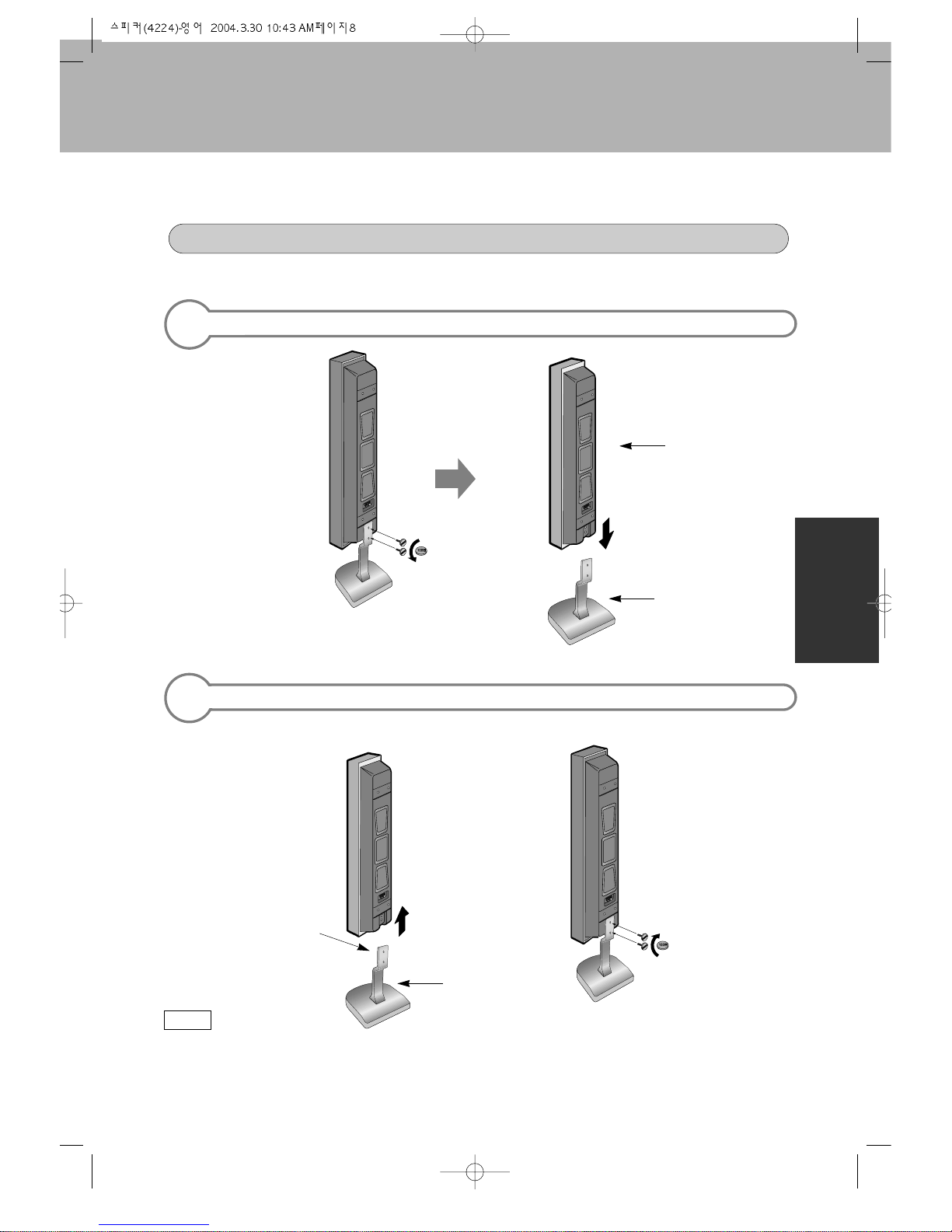
Do not use any parts other than those
enclosed. Do not leave out any part when assembling.
Please install all parts as indicated.
Do not alter or modify any parts Do not use the speakers with other products.
These speakers are specifically manufactured to be
used with the Gold vision Plasma display to
enhance your listening pleasure.
Do not allow a child to cling from or climb unto
the speakers Do not place the speakers on sloped or
unstable surfaces.
WARNING
CAUTION
WARNING : Disregarding these instructions can result in serious injury.
CAUTION : Disregarding these instructions will result in the mistreatment of
the unit and can result in injury or damage to the unit.
(Doing so may cause the speakers to fall off or
tip over causing injury and damage.)

PLASMA DISPLAY SPEAKER
4
S
P
E
A
K
E
R
Please be careful not to stain the speakers with
any gas or oil. When assembling, be sure to use the enclosed
parts and make sure all parts are tightly
screwed as instructed.
Do not place the speakers in a humid or dusty
place. Do not place the speakers near heating units.
Do not place speakers near a humidifier, or
cooking pots where speakers will be exposed
to steam or smoke.
Please be sure to connect (+) inputs and (-)
inputs correctly when connecting speakers to
plasma display.
*
PLEASE FOLLOW THESE SAFETY PRECAUTIONS WHEN INSTALLING OR HANDLING
(Failing to do so will cause the speakers to
vibrate and unable to produce clear sound.)
(Doing so will change the outer appearance)
(Failing to do so may alter the units)
(Failing to do so may cause discoloration or
damage to speakers) (If not connected correctly, it may result in distorted sound)
(Failing to do so will damage the speakers)

5
3. ASSEMBLING INSTRUCTIONS
USING SPEAKERS WHEN ATTACHED TO THE PLASMA DISPLAY
ATTACHING VIBRATION ABSORBENT SPONGES TO SPEAKERS
INSTALLING FIXED BRACKETS TO SPEAKERS
.Clean the surface with soft, lint-free cloth
where sponges will be attached. .Attach the sponge to the side of the
speaker that will be attached to the
plasma display.
Please leave a 5 mm space on the top
and bottom when attaching. Do not
cover the entire side with the sponge
as shown in the picture above.
5mm
(2inch)
5mm
(2inch)
.Install fixed brackets to speakers before
attaching speakers to plasma display.
Please make sure which side the fixed
brackets will be screwed to,
considering the left and right side of
speakers as shown in the picture to
the left.
Fixed brackets
Sponge-attached side
1
2
Note
Note
Bracket (A)
Bracket (C)
Bracket (B)
Bracket (C)

PLASMA DISPLAY SPEAKER
6
S
P
E
A
K
E
R
INSTALLING SPEAKERS TO THE PLASMA DISPLAY
.Place a protective covering over the surface you will be working on and lay
the plasma display as shown below.
.Take the speakers with fixed brackets to the back of the plasma display. Place the hooks onto
the fixed brackets to the squared holes in the back of the plasma display.
.Now tightly secure the
hooks with the M4 screws.
Hooks
3
Note
.Please be sure to secure the screws to avoid
any shaking or looseness.

7
CONNECTING SPEAKER WIRES
.Take the speaker wire(2) and use the red cord to connect to and fro (+) inputs,
and use the black cord to connect to and fro (-) inputs.
4
.Please be sure to connect red cord with (+) and black with (-); otherwise,
speakers will not produce clear sounds.
.Please retain the left over accessories.
.Connecting Clamp Wires:
- It is used keeping a speaker wire (A speaker wire is connected the back
side of main body) as a ficture.
Note

PLASMA DISPLAY SPEAKER
8
S
P
E
A
K
E
R
UNINSTALLING SPEAKERS FROM ITS OWN STAND.
.Please, use a coin to
loosen the special
screws.
INSTALLING SPEAKERS TO ITS OWN STAND OR UNINSTALLING SPEAKERS FROM ITS OWN STAND
Stand
1
.To avoid loose fitting, please be sure that screws are secured tightly.
Otherwise, vibrating or distorted sounds may be produced.
Note
Speaker
INSTALLING SPEAKERS TO ITS OWN STAND.
2
.Use a coin to secure
the special screws
(round head screws)
tightly.
Please be sure to have
the vibration absorbent
sponge onto the side of
the speaker where the
stand will be attached.
Stand

HW
AA
NL
GL
E
R
U
N
I
T
PLASMA MONITOR (DISPLAY)
WALL HANGER UNIT
Thank you for purchasing the Gold vision Plasma Display Wall Hanger Unit. This wall unit
is specifically designed for use with the Gold vision Plasma Display. To ensure the safe
operation of the unit, please read these instructions before installing.
INSTRUCTION MANUAL
GV-H42G

1
TABLE OF CONTENTS
1. Check for enclosed parts .............................. 2
2. Important Safety Instructions ........................ 3
3. Assembly Instructions ...................................6
4. Adjusting angles after installation ................12
*
To install the wall hanger unit, Please
consult an Authorized service center first.

PLASMA DISPLAY HANGER UNIT
2
HW
AA
NL
GL
E
R
U
N
I
T
1. PLEASE CHECK THE ITEMS SHOWN BELOW
(2)
FRAME SET A FRAME SET B
CONNECTING FRAME CONCRETE WALL ANCHOR
M5 SCREWS (20 MM) WALL SCREWS
PAPER PATTERN PLAN M5 SCREWS (30MM)
(2)
(1) (8)
(8) (8)
(1) (2)
Paper pattern plan

3
2. IMPORTANT SAFETY INSTRUCTIONS
WARNING : Disregarding these instructions can result in serious injury.
CAUTION : Disregarding these instructions will result in the mistreatment of
the unit and can result in injury or damage to the unit.
PLEASE KEEP THESE INSTRUCTIONS FOR YOUR SAFETY AND TO PREVENT ANY DAMAGE TO THIS UNIT.
PLEASE FOLLOW THESE INSTRUCTIONS FOR YOUR SAFETY
(Failing to do so may cause the unit to fall and break) (Failing to do so may cause the unit to fall and break)
(Failing to do so may cause the unit to fall and break) (Failing to do so may cause the unit to vibrate and to fall)
(Failing to do so may cause the unit to fall and break) (Failing to do so may cause the unit to fall and break)
To install the wall hanger unit, please consult
an Authorized service center first. The wall hanger unit needs to be installed
securely enough to handle earthquakes or
lengthy periods of vibration.
When assembling, do not use any parts other
than those enclosed and secure all parts tightly. Do not leave out any part when assembling.
Please install all parts to where indicated.
Do not alter or modify any parts Donotusethewallhanger unitwithother products. This
wallhanger unitisspecifically designed tofitthe Gold vision
PlasmaDisplay.
*
PLEASE CONSULT AN AUTHORIZED SERVICE CENTER TO INSTALL THE WALL HANGER UNIT
WARNING
CAUTION

PLASMA DISPLAY HANGER UNIT
4
HW
AA
NL
GL
E
R
U
N
I
T
Special care is needed when installing onto the
wall due to its weight (35Kg)
When installing on a concrete wall
Please be sure to use the enclosed concrete
anchors.
When installing on a wooden walltake special
care as the unit may require extra support to
uphold the weight of the plasma display.
When installing, please wear working gloves.
Be sure that no one is around to distract you
during the installation process.
When installing, please have at least two
people. Please choose a wall that is straight so that the
plasma display can be securely attached onto the
wall.
Place a protective covering over the surface you will
be working on when handling the plasma display and
the wall hanger units.
*
PLEASE FOLLOW THESE SAFETY PRECAUTIONS WHEN INSTALLING OR HANDLING
(If done with bare hands, it may result in injury)
(It may result in injury to you or others)
(If attached on an unstable wall, the unit can fall and
break)
(Because of its weight, the unit may fall and can cause
injury)
(Failing to do so may result in unwanted marks on the
unit)
After installing, please be sure to check to see if the
unit has been secured firmly.

5
It is important to use the paper pattern plan to choose the proper place; otherwise, it can result in
damage to the wall and you will not be able to install the unit
If proper spacing is not allowed, it may cause the plasma display to overheat, which can cause fire or
damage to the unit
When installing, please use the size referenced below to choose a place, and attach
the paper pattern plan to the wall.
When installing, please allow at least 15 cm at the top, bottom, left and right on the
wall, and clear all items away from where the unit will be.
*
PLEASE FOLLOW THESE SAFETY PRECAUTIONS WHEN INSTALLING OR HANDLING
519.5
.Measurement unit : mm
519.5
314
314
15cm
15cm
15cm
15cm
Paper pattern plan

PLASMA DISPLAY HANGER UNIT
6
HW
AA
NL
GL
E
R
U
N
I
T
3. ASSEMBLING INSTRUCTIONS
PREPARATION
WHEN THE PLASMA DISPLAY IS ATTACHED TO THE STAND
TO DETACH THE STAND FROM THE PLASMA DISPLAY
.To avoid unwanted marks on the unit, place
a protective covering over the surface you
will be working on and lay the plasma
display as shown below.
.Unscrew the secured 4 screws completely
and Pull the stand away from the plasma
display to detach.
1

7
INSTALLING THE WALL FRAME SET A ON THE PLASMA DISPLAY
HOW TO DISPOSE OF THE PLASMA MONITOR WRAPPER
HOW TO INSTALL FRAME SET A ON THE UNIT
.First discard the wrapping band and
raise the top box to open. .Afterwards, dispose of the Styrofoam
and remove the vinyl covering.
.To avoid unwanted marks on the unit, place
a protective covering over the surface you
will be working on and lay the plasma display
as shown in the picture below.
.When securing frame set A to the plasma display, make sure that they match the holes correctly.
.If holes are matched incorrectly, installation will not be successful.
.Place frame set A on the left and right
side of the unit and use the enclosed
screws (M5) to secure them tightly.
(left and right 2 each)
1
2
Note

PLASMA DISPLAY HANGER UNIT
8
HW
AA
NL
GL
E
R
U
N
I
T
INSTALLING WALL FRAME SET B AND CONNECTING FRAME
INSTALLING WALL FRAME SET B AND CONNECTING FRAME.
ATTACHING PAPER PATTERN PLAN ON THE WALL
.Place frame set B on the left and right side of
the unit and use the enclosed screws (M5) to
secure them tightly.
.Place the enclosed paper pattern
plan (actual size) on the wall with
glue or tape.
.Drill holes on the wall as indicated
on the paper pattern plan with a
hand drill (power drill) and hammer
in the concrete anchors (8) firmly.
Connecting Frame
Frame set B
Hand drill
Paper pattern plan
Paper pattern plan
1
2
.Please be sure to not force an
adjustment when connecting frame
set B and connecting frame.
.Otherwise, it will create problems
when connecting to frame set A.
Note

9
INSTALL THE WALL FRAME SET ON THE WALL
.Install the wall frame set on the wall by matching the concrete anchors with the holes,
then use the wall screws (8) to secure tightly.
Paper pattern plan
3
INSTALLING ON THE WALL HELD BY SUPPORTING WOODEN STRUCTURE
.If it is not feasible to attach frame set B firmly and completely, due to the distance
between the two supporting woods; attach one side of the frame set B firmly to the
supporting wood, and use appropriate remaining holes(6) to attach the frame set B
to the supporting wooden structures.
4
Paper pattern plan
This manual suits for next models
2
Table of contents