Golden Valley MC107 User manual

OPERATOR’S MANUAL
GOLDEN VALLEY
MC107 MOWER CADDY

Golden Valley Mower Caddy MC107 Page 2
TABLE OF CONTENTS
Introduction...................................................................................... Page 3
Warranty Information....................................................................... Page 3
Dealer Checklist ................................................................................ Page 4
Safety ............................................................................................... Page 5-9
Before Operation .................................................................... Page 6
During Operation .................................................................... Page 7
Highway Transportation.......................................................... Page 8
Maintenance........................................................................... Page 8
Parts List ........................................................................................... Page 11-17
Installation Instructions .................................................................... Page 18
Maintenance Instructions ................................................................. Page 19
U.S. Bolt Torque Specifications ......................................................... Page 20
Warranty Registration

Golden Valley Mower Caddy MC107 Page 3
INTRODUCTION
Thank you for selecting one of our many Golden Valley products. We hope you enjoy many
years of use and productivity of this equipment. Please read this manual before operation to
understand its proper use, and do not use equipment for anything other than its intended
purpose.
LIMITED WARRANTY
Golden Valley, by Bramco Inc., warrants its products to be free from defects in material or
workmanship, under normal intended use, for a period of one year from the date of sale to the
original private owner. The warranty term for commercial use of equipment (including rental) is
limited to six months from the date of original sale.
Golden Valley is not liable for any incidental or consequential loss or damages including but not
limited to loss of use, loss of profits and damage to the equipment to which the Golden Valley
product is attached.
The customer is required to complete and return to Bramco Inc. the Warranty Registration at
the end of this manual prior to any warranty claims or repairs to be performed.
Golden Valley limited warranty covers parts and labor for authorized repairs. All warranty
claims must be authorized prior to starting repairs. Your dealer must request a Warranty
Authorization Form.
The Limited Warranty of the product is void if the equipment has been altered or modified from
its original state in any way. The equipment will not be covered under warranty as well if there
are signs of any misuse, accidents, improper maintenance, or if the serial tag has been
removed, altered, or defaced. Normal wear items are not covered under warranty which
include but are not limited to blades, hoses, tires, couplers, etc.
Golden Valley reserves the right to alter, update, or improve its products at any time without
incurring any obligation to past customers.
For future reference, please complete the information below:
MODEL NUMBER ___________________
SERIAL NUMBER ___________________
PURCHASE DATE ___________________

Golden Valley Mower Caddy MC107 Page 4
DEALER CHECKLIST
Inspect the equipment thoroughly to be certain it is set up properly before items are to be
received by the customer. The following check list is a reminder of points to inspect.
Check off each item if it is found satisfactory or after proper adjustment is made.
__ All component parts are included with the equipment
__ Wheel bolts are tight
__ Fasteners are tight
__ Hydraulic hoses are free
__ Hydraulic fittings are tight
__ Lift arms rotate properly
__ Driveline turns freely
__ Tire pressure has been checked
__ Bearings and wear points are lubricated
__ All decals are installed
__ Guards and shields installed
__ Review operating and safety instructions with the customer
It is recommended at the time of delivery to fill out the Warranty Registration Form (found at
the end of this Operator’s Manual) with the customer. All Warranty Registration information
must be completed and returned to Bramco Inc. for any warranty claims to be valid.

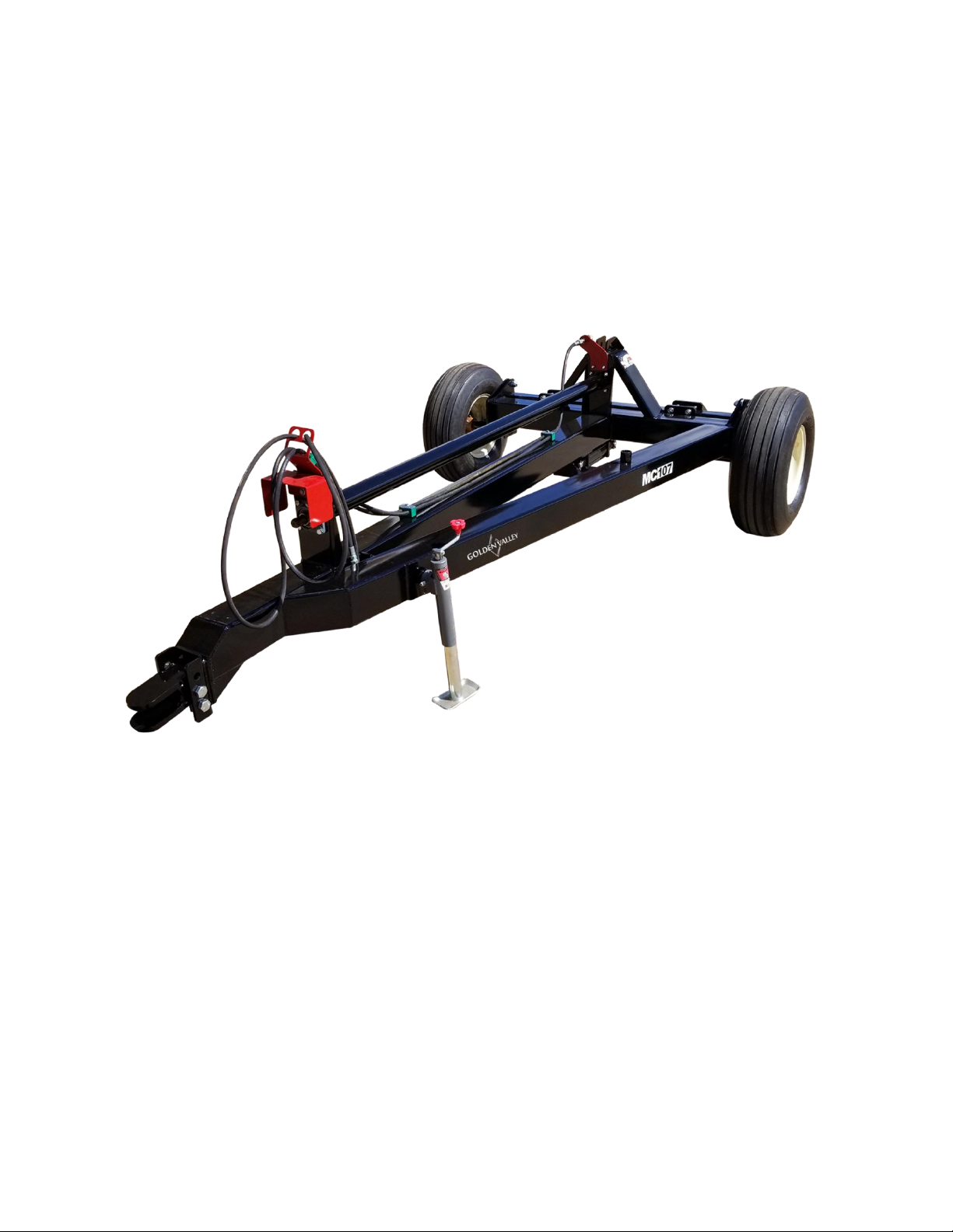
Golden Valley Mower Caddy MC107 Page 5
SAFETY
Your manual contains special messages to bring attention to potential safety concerns, machine
damage as well as helpful operating and servicing information. Please read all the information
carefully to avoid injury and machine damage.
This safety alert sign is used in this book and on your equipment. When you
see this sign, carefully read what it says. YOUR SAFETY IS AT STAKE. The safety
sign will be used with these words: Danger, Warning, and Caution.
IMPORTANT SIGNAL WORDS
DANGER: Indicates an imminently hazardous situation that, if not avoided, will result in death
or serious injury. This work is to reference the most extreme situations, typically for machine
components which cannot be guarded.
WARNING: Indicates a potentially hazardous situation that, if not avoided could result in death
or serious injury. This will include hazards that are exposed when guards are removed, and an
alert against unsafe practices.
CAUTION: Indicates a potentially hazardous situation that, if not avoided, may result in minor
or moderate serious injury. It may also be used to alert against unsafe practices.
SAFETY GUIDELINES
Safety of the operator, as well as those around the operator, is one of the main concerns in
designing and developing a piece of equipment. Designers and manufacturers build in as many
safety features as possible. However, every year many accidents occur which could have been
avoided by a few seconds of thought and a more careful approach to handling equipment. You,
the operator, can avoid many accidents by observing the following precautions in this section.
To avoid personal injury, study the following precautions and insist those working with you, or
for you, to follow them.
Do not attempt to operate this equipment under the influence of drugs or alcohol.
Review the safety instructions with all user annually.
This equipment is dangerous to children and personnel unfamiliar with tits operation. The
operator should be a responsible adult familiar with farm machinery and trained in this

Golden Valley Mower Caddy MC107 Page 6
equipment’s operation. Do not allow persons to operate or assemble this unit until they have
read this manual and have developed a thorough understanding of the safety precautions and
of how it works.
To prevents injury or death, use a tractor equipped with a Roll-over Protective System (ROPS).
Do not paint over, remove, or deface any safety sings or warning decals on your equipment.
Observe all safety signs and practice the instructions on them.
Never exceed the limits of a piece of machinery. If its ability to do a job, or to do so safely is in
questions –DO NOT TRY IT!
SAFETY SIGNS
Good safety practices require that you familiarize yourself with the various safety signs on your
equipment.
Keep safety signs clean and legible at all times
Replace safety signs that are missing or have become illegible
Safety signs can be acquired from your distributor, dealer, or directly from Golden Valley.
BEFORE OPERATION
Carefully study and understand this manual
Do not wear loose fitting clothing which may catch in moving parts.
Always wear proper Personal Protective Equipment (PPE) to suit conditions of the job
Give the units a visual inspection for any loose bolts, worn parts or cracked welds and make any
necessary repairs.
Move tractor wheels to the widest recommended settings to increase stability
Grease all fittings on the moving parts when indicated
Ensure that there are no tools lying on or in the equipment
Always shut off tractor engine, disengage P.T.O., shift to “Park” position (or neutral), set brakes
and allow machine to completely stop before dismounting tractor or working around machine.
Do not stand between tractor and implement to install hitch pin when tractor engine is running.
Never leave running equipment unattended

Golden Valley Mower Caddy MC107 Page 7
DURING OPERATION
Do not carry passengers anywhere on or in the tractor or equipment except as required for
proper operation.
Do not clean lubricate or adjust your equipment while it is moving.
When halting operation even periodically, set the tractor or towing vehicle brakes, disengage
the PTO, shut off the engine and remove the ignition key.
Be very observant of the operating area and terrain. Watch for holes, rocks or other hidden
hazards. Always inspect the area prior to operation. Do not operate near the edge of drop offs
or banks. Do not operate on steep slopes as overturn may result. Operate up and down (not
across) intermediate slopes. Avoid sudden starts and stops.
Pick the most level possible route when transporting across fields.
Maneuver the tractor or towing vehicle at safe speeds.
Avoid overhead wires or other obstacles. Contact with overhead lines could cause serious injury
or death.
Avoid loose fill, rocks, and holes as they can be dangerous for equipment operation or
movement.
Beware of bystanders, particularly children. Always look around to make sure that it is safe to
start the engine of the towing vehicle or move the unit. It is particularly important with higher
noise levels and quiet cabs, as you may not hear people shouting.
Do not walk or work under raised components or attachments.
Keep all bystanders, pets, and livestock clear of the work area.
Operate the towing vehicle from the operator’s seat only
Always turn off the towing vehicle when leaving the operator seat and when leaving equipment
unattended
Do not clean, lubricate, or adjust or equipment while it is moving.
As a precaution, always recheck the hardware on equipment following every 100 hours of
operation. Correct all problems, Follow the maintenance safety procedures.

Golden Valley Mower Caddy MC107 Page 8
After the first few hours of operation, check all bolts, drivelines, locking collar on driveline, and
all parts related to the mower’s safe operation.
HIGHWAY AND TRANSPORT OPERATION
It is the responsibility of the customer to know the lighting and marking requirements of the
local highway authorities and to install and maintain the equipment to provide compliance with
regulations.
Adopt safe driving practices
Keep the brake pedals latched together at all times
Always drive at a safe speed relative to local conditions, and ensure you are slow
enough in the event of an emergency stop
Reduce speed prior to turns to avoid overturning
Avoid sudden uphill turns on steep slopes
Always keep the tractor or towing vehicle in gear to provide engine braking when going
downhill. Do not coast.
Do not drink and drive.
Plan your route to avoid heavy traffic
Be a safe and courteous driver. Always yield to oncoming traffic, including narrow bridges,
intersections, etc.
Be observant of bridge loading ratings. Do not cross bridges rated lower than the gross weight
at which you are operating.
Watch for obstruction overhead and to the side while transporting.
Make allowances for increased length and weight of the equipment when making turns and
stopping.
Never exceed the recommended speed limit rating for your tires.
PERFORMING MAINTENANCE
Good maintenance is your responsibility. Not properly maintain your machine can lead to
damage meaning repairs that could have been avoided.
Make sure there is plenty of ventilation. Never operate the engine of the towing vehicle in a
closed building. The exhaust fumes may cause asphyxiation.

Golden Valley Mower Caddy MC107 Page 9
Before working on the machine –stop the towing vehicle, set the brakes, disengage the PTO
and all power drives, shut off the engine and remove the ignition keys.
Be certain all moving parts on attachments have come to a complete stop before attempting to
perform maintenance.
Always use a safety support and block the wheels. Never use a jack to support the machine
during maintenance.
Follow the torque chart in the manual when tightening bolts and nuts.
Never use your hands to locate a hydraulic leak on attachments. Use a small piece of cardboard
or wood. Hydraulic fluid under pressure can penetrate the skin.
When disconnecting hydraulic lines, shut off hydraulic supply and relieve all hydraulic pressure.
Openings in the skin ad minor cuts are susceptible to infection from hydraulic fluid. If injured by
escaping hydraulic fluid, see a doctor at once. Gangrene can result without immediate medical
treatment.
Replace all shields and guards after servicing and before moving.
After servicing, be sure all tools, parts and service equipment are removed
Do not allow grease or oil to build up on any step or platform
Never replace hex bolts with less than grade five bolts unless otherwise specified. Refer to bolt
torque chart for head identification marks.
Where replacement parts are necessary for periodic maintenance and servicing, genuine
factory replacement parts must be used to restore your equipment to original specifications.
Golden Valley will not claim responsibility for use of unapproved parts and/or accessories and
other damages as a result of their use.
A fire extinguisher and first aid kit should be kept readily accessible while performing
maintenance on any equipment.

Golden Valley Mower Caddy MC107 Page 10
PAGE INTENTIONALLY LEFT BLANK

Golden Valley Mower Caddy MC107 Page 11
MC107 MOWER CADDY PARTS LIST

Golden Valley Mower Caddy MC107 Page 12
MAINFRAME ASSEMBLY

Golden Valley Mower Caddy MC107 Page 13
MAINFRAME ASSEMBLY (CONT.)
ITEM
NO.
PART
NUMBER
DESCRIPTION
QTY.
1
--
MAINFRAME
1
2
401642
CLEVIS HITCH
1
3
018294
7/8" X 7" BOLT
2
4
018301
7/8" LOCKWASHER
2
5
018308
7/8" HEX NUT
2
6
018123
11L X 15 TIRE/WHEEL ASSY
2
7
PAGE 16
HUB/SPINDLE ASSY
2
8
018280
1/2" LUG NUT
12
9
014729
1/2" X 3" BOLT
2
10
014323
1/2" NYLOCK NUT
2
11
018051
5000# JACK STAND
1
12
112712
PTO COVER
1
13
112684
HOSE HOLDER
1
14
018094
TWIN HOSE CLAMP
3
16
014722
3/8" X 1-1/2"
4
17
014579
3/8" FLATWASHER
6
18
014450
3/8" NYLOCK NUT
4
19
018080
CAT 2 TOP LINK
1
20
018087
CAT 2 TOP LINK PIN
1
21
014331
LYNCH PIN
1
22
016162
FEMALE COUPLER
1
23
018144
MOWER HYD. HOSE
1
24
112593
HYD. COUPLER MOUNT
11

Golden Valley Mower Caddy MC107 Page 14
LIFT ASSEMBLY
ITEM NO.
PART NUMBER
DESCRIPTION
QTY.
1
--
LIFT TUBE
1
2
401628
LIFT ARM
2
3
112565
LIFT ARM BOLT PLATE
2
4
018315
3/4" X 6-1/2" BOLT
8
5
011171
3/4" LOCKWASHER
8
6
011163
3/4" HEX NUT
8
7
018322
1" X 3-1/2" BOLT
2
8
013821
1" NYLOCK NUT
2
9
018329
GREASE ZERK
2

Golden Valley Mower Caddy MC107 Page 15
DRIVELINE ASSEMBLY
ITEM NO.
PART NUMBER
DESCRIPTION
QTY.
1
401670
CADDY DRIVELINE
1
2
018044
4 BOLT FLANGE BEARING
2
3
018337
1/2" X 1-3/4" BOLT
8
4
014323
1/2" NYLOCK NUT
8

Golden Valley Mower Caddy MC107 Page 16
HUB/SPINDLE ASSEMBLY
ITEM NO.
PART NUMBER
DESCRIPTION
QTY.
1
018258
HUB CAP
2
2
018244
COTTER PIN
2
3
018237
CASTLE NUT
2
4
018251
WASHER
2
5
018215
OUTER BEARING
2
6
018272
GREASE ZERK
2
7
018280
LUG NUT
12
8
018116
6 BOLT HUB W/RACES
2
9
018265
STUD BOLT
12
10
018222
INNER BEARING
2
11
018230
HUB SEAL
2
12
018101
SPINDLE
2
ITEM NO.
PART NUMBER
DESCRIPTION
QTY.
018287
COMPLETE HUB KIT
2
018344
COMPLETE SPINDLE KIT
2

Golden Valley Mower Caddy MC107 Page 17
HYDRAULIC OPTION
MANUAL OPTION
ITEM NO.
PART NUMBER
DESCRIPTION
QTY.
1
018137
RATCHET JACK ASSEMBLY
1
ITEM NO.
PART NUMBER
DESCRIPTION
QTY.
1
018657
LIFT CYLINDER
1
2
INCLUDED
CYLINDER PIN
2
3
018151
VENT CAP
1
4
016504
90 DEGREE FITTING
1
5
018130
BALL VALVE
1
6
018144
LIFT HYDRAULIC HOSE
1

Golden Valley Mower Caddy MC107 Page 18
INSTALLATION INSTRUCTIONS
The tractor’s drawbar must be set at a distance of 14” from the end of the PTO shaft to the
center of the drawbar pin hole. This distance is standard for 540 PTO drives and will maintain a
proper relationship for driveline angles and help improve the life of the driveline.
The hitch is designed to give three height positions. The hitch must be set to the proper hitch
height to keep the mower caddy parallel to the ground.
NOTE: When installing the TOP LINK, keep the same amount of threads showing on each end.
This will allow a full range of adjustment for the TOP LINK.
Check for proper driveline length –due to variations in tractors and implements, drivelines may
need to be adjusted in length.
Separate the two halves of the driveline, and connect one half to the tractor and the other half
to the caddy
Turn the tractor at a sharp angle to determine the shortest positions of the driveline. There
should be at least 1-1/2” or more clearance from the tubes “bottoming out” at this maximum
compression length. If necessary, shorten the driveline to obtain proper clearance.
Turn the tractor and mower caddy into a straight line to determine the longest position
required of the driveline. Check the driveline length at this maximum extension to make sure
that the metal tubes are always engage at least 8 inches.
CAUTION –Do not shorten more than necessary. Shorten the metal tubes and guards
by the same amount and round off all sharp edges. Grease the metal tubes before assembly.
GREASE DRIVELINES DAILY. If not properly greased, severe damage will occur to drivelines and
attaching components.
When installing the disc mower to the caddy, follow the guidelines that are furnished by the
disc mower’s manufacturer.

Golden Valley Mower Caddy MC107 Page 19
MAINTENANCE INSTRUCTIONS
Before operating equipment for the first time, please read the Operator’s Manual in its
entirety. Review periodically for reminders of safety precautions and maintenance procedures.
Inspect all bolts to ensure that they are tightened properly. You may refer to the U.S.
Bolt Torque Specifications chart at the back of this manual. .
Inspect tires for proper tread, inflation, and tire pressure. Tire pressure should be at 36
psi. Grease wheel bearings with high temperature grease.
Check grease zerks to ensure proper lubrication of rotating parts. Please refer to the
diagram below for grease zerk locations.
Check all hydraulic hoses and fittings for any damage, and that they are properly
secured. Replace any cracked or leaking hoses.
All hardware on equipment should be checked every 100 hours of operation, and
correct any issues before its next use.
Be aware to use only Golden Valley recommended replacement parts for any repairs.
GREASE ZERK LOCATIONS

Golden Valley Mower Caddy MC107 Page 20
U.S. BOLT TORQUE SPECIFICATIONS
U.S. BOLT GRADES
SAE 2
SAE 5
SAE 7
SAE 8
SOCKET HEAD
SCREW CAP
I.D. Marks
No markings
3 lines
5 lines
6 lines
Allen Head
Material
Low Carbon
Medium-
carbon,
tempered
Medium-
carbon,
quenched &
tempered
Medium-
carbon,
quenched &
tempered
High-carbon,
quenched &
tempered
Tensile Strength
(Minimum)
74,000 psi
120,000 psi
133,000 psi
150,000 psi
160,000 psi
U.S. BOLT TORQUE SPECIFICATIONS
Torque in pounds-foot
2
2
5
5
7
7
8
8
Socket
head cap
screw
Socket
head cap
screw
Bolt
Dia.
Thread
per inch
Dry
Oiled
Dry
Oiled
Dry
Oiled
Dry
Oiled
Dry
Oiled
3/8
16
16
12
30
23
40
30
45
35
49
39
3/8
24
22
16
35
25
45
35
50
40
54
44
1/2
13
38
31
75
55
95
70
110
80
113
90
1/2
20
52
42
90
65
100
80
120
90
126
100
3/4
10
157
121
260
200
320
240
380
280
400
320
3/4
16
180
133
300
220
360
280
420
320
440
350
7/8
9
210
160
430
320
520
400
600
460
640
510
7/8
14
230
177
470
360
580
440
660
500
700
560
1
8
320
240
640
480
800
600
900
680
980
780
1
12
350
265
710
530
860
666
990
740
1060
845
Table of contents