goldstein 800 Series User manual

Installation and Operation Manual
800 SERIES GAS V FRYER
Models: VFG-1
VFG-T
VFG-24

2
Manufacturer:
Goldstein Eswood Commercial Cooking PTY LTD
For inquiries please call your nearest state branch or visit our website.
New South Wales –Head Office
Address: 211 –217 Woodpark Road,
Smithfield NSW 2164
Phone: +61 (02) 9604 7333
Fax: +61 (02) 9604 5420
Victoria
Address: 47 Stubbs Street,
Kensington Victoria 3031
Phone: +61 (03) 9372 6577
Fax: +61 (03) 9372 6477
Queensland
Address: Unit 12, 210 Queensport Road,
North Murarrie Queensland 4172
Phone: +61 (07) 3890 1811
Fax: +61 (07) 3890 1788
Western Australia
Address: Unit 2, 9 Meares Way,
Canning Vale Western Australia 6155
Phone: +61 (08) 9456 0559
Fax: +61 (08) 9456 0554
Tasmania
Phone: +61 (03) 9372 6577
Fax: +61 (03) 9372 6477
South Australia
Phone: 1800 013 123
New Zealand
Phone: +64 7 348 8430
Fax: +64 7 347 1833
Sales & Enquiries
Sales: sale[email protected]
Web: www.goldsteineswood.com.au
www.middleby.com.au
Toll Free
Phone: 1800 013 123

Contents
3
1. Contents
1. CONTENTS......................................................................................................................................3
2. INTRODUCTION ...............................................................................................................................4
3. SPECIFICATIONS...............................................................................................................................5
4. DIMENSIONS...................................................................................................................................6
5. INSTALLATION .................................................................................................................................9
6. OPERATION ..................................................................................................................................12
7. CLEANING AND MAINTENANCE ........................................................................................................14
8. TROUBLE-SHOOTING......................................................................................................................16
9. GAS CONVERSION..........................................................................................................................17
10. WIRING DIAGRAMS .......................................................................................................................18
11. SPARE PARTS ................................................................................................................................19
12. WARRANTY ..................................................................................................................................22

Introduction
4
2. Introduction
Congratulations on purchasing your Goldstein commercial cooking appliance. Goldstein Eswood
Commercial Cooking is an Australian company and has been operating since 1911, building high
quality products.
The information contained in this manual will assist your installer and ensure correct location and
connection. Thoroughly read the user instructions and the user maintenance sections, as
understanding your products, its operation, and its cleaning and service requirements will provide
you with long and satisfactory service. Neglecting regular cleaning and maintenance could shorten
the life of the product and decrease its efficiency. Please ensure only authorised service technicians
are called to any difficulties that may arise.
2.1 Safety Notice
The below symbols may be used in isolation or combination throughout this manual. Where used,
these symbols are intended to alert personnel of potential risk, either to themselves or to the
equipment and/ or convey important messages regarding the safe operation and maintenance of
the appliance.
WARNING
Improper installation, adjustment, alteration, service or maintenance can cause property
damage, injury or death. Please read the installation, operating and maintenance instructions
thoroughly before installing or servicing this appliance.
CAUTION
This appliance is intended for professional use and is only to be used by trained, qualified
personnel.
Installation, maintenance and repairs should be performed by an authorized Goldstein Eswood
service agent or other qualified personnel. Installation, maintenance or repairs by an
unauthorized and unqualified personnel will void the warranty.
WARNING
DO NOT store or use gasoline, flammable vapours and liquids or any other flammable material
near this or any other appliance. Do not spray aerosols near this appliance whilst in operation.

Specifications
5
3. Specifications
3.1 General Description
A commercial, heavy duty gas fryer with fast heating and economic oil requirements. The ‘V’ shaped
tank design is automatically controlled by a gas-powered valve with an inbuilt regulator. The body is
made from high grade stainless steel for lasting durability and finish.
3.2 Model numbers covered in this manual:
▪VFG-1 - Single 20L Tank
▪VFG-T - Double 16L per Tank
▪VFG-24 - Single 36L Tank
3.3 Gas Supply Requirements:
Natural Gas
LPG (Propane)
VFG-1
97 MJ/hr
95 MJ/hr
VFG-T
105 MJ/hr
100 MJ/hr
VFG-24
127 MJ/hr
127 MJ/hr
Supply Pressure
1.13 –3.5 kPa (5.0 SIT NOVA)
2.75 –3.5 kPa (5.0 SIT NOVA)
Operating Pressure
1.00 kPa (0.7kPa VFG24)
2.50 kPa
Gas Connection
¾” BSP Male
The operating pressure is factory pre-set and should not be adjusted. However, if further adjustment
is required, measure the operating pressure at the test point and proceed to adjust pressure at the
appliance gas valve with the unit running. Refer to the Gas Conversion section of this manual for
more detailed instructions.
3.4 Injector Sizes
Model
Gas Type
Main Injector
Lighting Injector
Rear Injector
Pilot Injector
VFG-1
NG
1.5
1.4
NA
0.51
LPG
0.95
0.85
NA
0.35
VFG-T
NG
1.5
NA
NA
0.51
LPG
0.95
NA
0.85
0.35
VFG-24
NG
1.95
1.75
1.3
0.55
LPG
1.2
1.05
0.85
0.35
3.5 Rating Plate Data
Rating plates are marked with the appropriate corresponding injector sizes i.e.:
L: Lighting injector M: Main injector R: Rear injector
NOTE: Injectors listed in the data table with N/A are MAIN injector sizes relative to the appropriate
model and gas type. The stamped number on the head of the pilot is not a dimension.

Dimensions
6
4. Dimensions
4.1 VFG-1
Note: Dimensions may change without notice in accordance with product design and development

Dimensions
7
4.2 VFG-T
Note: Dimensions may change without notice in accordance with product design and development

Dimensions
8
4.3 VFG-24
Note: Dimensions may change without notice in accordance with product design and development

Installation
9
5. Installation
Goldstein 800 Series V Fryers are designed to give long and satisfactory service and incorporate the
best possible materials and workmanship. Proper installation and preventative maintenance are vital
for optimum performance and efficiency.
5.1 Receiving Inspection & Unpacking
▪Remove carton, packaging and all plastic protective material from the appliance.
▪Check for damages to the appliance and report any damage to the transport company and
dealer.
▪Ensure all loose packaged items i.e. legs, baskets, basket holder, trays and warranty cards
are provided with the unit and report any missing items to the dealer.
▪Check that the rating plate- located on the back of the door- corresponds with the available
gas supply.
5.2 Installing into Location
▪This appliance must be installed under an exhaust hood with adequate means of ventilation.
Do not block, obstruct or connect a ventilation system directly to the appliance flue.
▪Lift off the base and screw in the adjustable legs provided with the appliance. Do not install
the appliance without the legs or place any obstructions in and around the base. Primary air
for burner combustion is supplied through the base of the appliance and must be kept clear
of obstructions.
▪Position the appliance into the correct position.
▪Level off the unit from left to right with a spirit level by rotating the feet. Also, level front to
back with a fall of 2-3mm to the front to improve appliance ventilation & flue efficiency.
5.3 Installation Clearances
The following table shows the required clearances around this appliance to ensure correct and safe
operation to the user, the appliance and its surroundings. Please refer to AS5601 or AS/NZS5601 for
detailed gas installation requirements.
Combustible material
Non-combustible material
Back
150mm
0mm
Sides
100mm
0mm
WARNING
This appliance must be installed by authorized personnel and in accordance with AS5601 &
AS/NZS5601 –Gas Installations and manufacturer’s specifications outlined in this manual.
Installation, maintenance or repairs by unauthorized and unqualified personnel will void the
warranty.

Installation
10
WARNING
This appliance must be installed by a qualified gas fitter or plumber and in accordance with
AS5601 & AS/NZS5601.
5.4 Gas Connection
This appliance has been tested and pre-set before leaving the factory, however minor adjustments
may be necessary to suit the gas supply pressure. Correct operation of the appliance must be tested
as part of the installation procedure.
Note: Gas fitting must only be carried out by an authorised and qualified person.
1. Have a licensed gas fitter or your gas supply company
connect & check that the gas supply line pressure and
volume are adequate for the appliance being installed.
The required pressure and input rating is shown on the
rating plate behind the door.
2. Install the appliance in accordance with AS5601 &
AS/NZS5601. Ensure that the appliance gas type
corresponds with the gas supply. Different gas types
are NOT compatible; however, the appliance can be converted from one gas type to
another. Please see conversion instructions for more details and contact the dealer for any
necessary components.
3. Fit an individual manual isolating valve to the appliance gas supply.
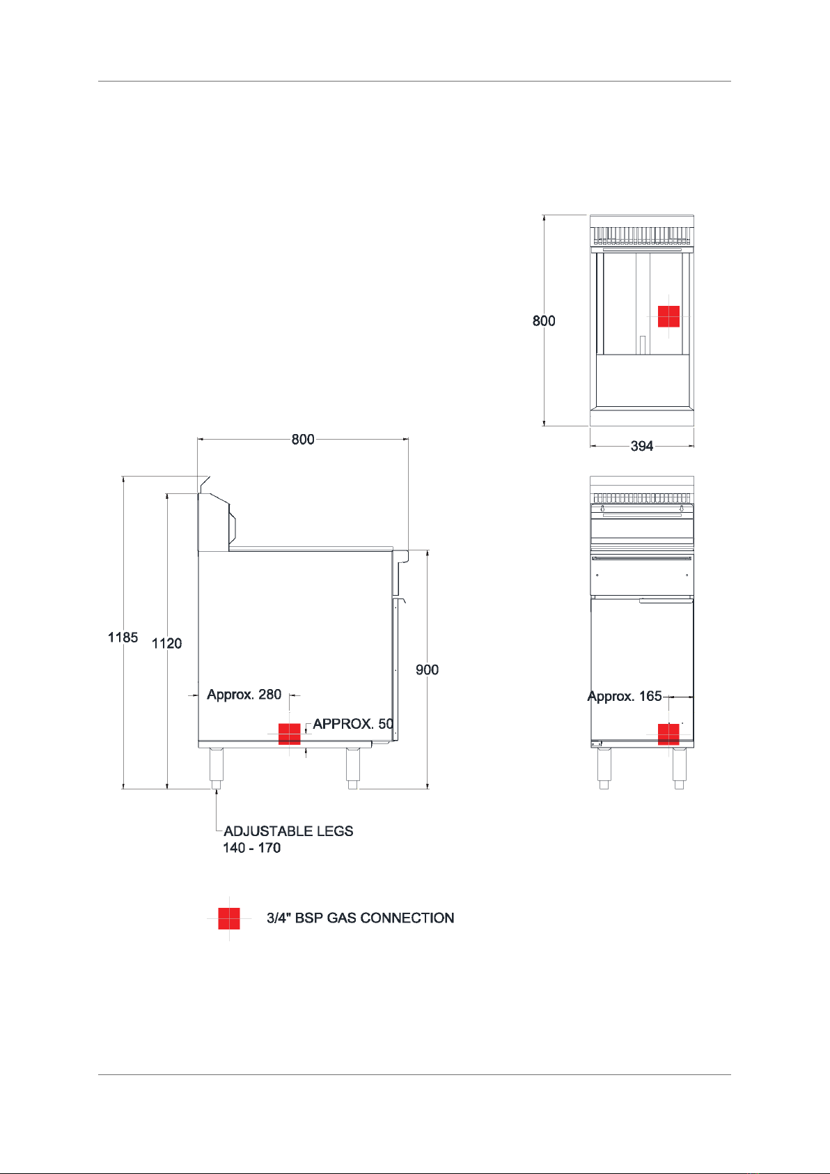
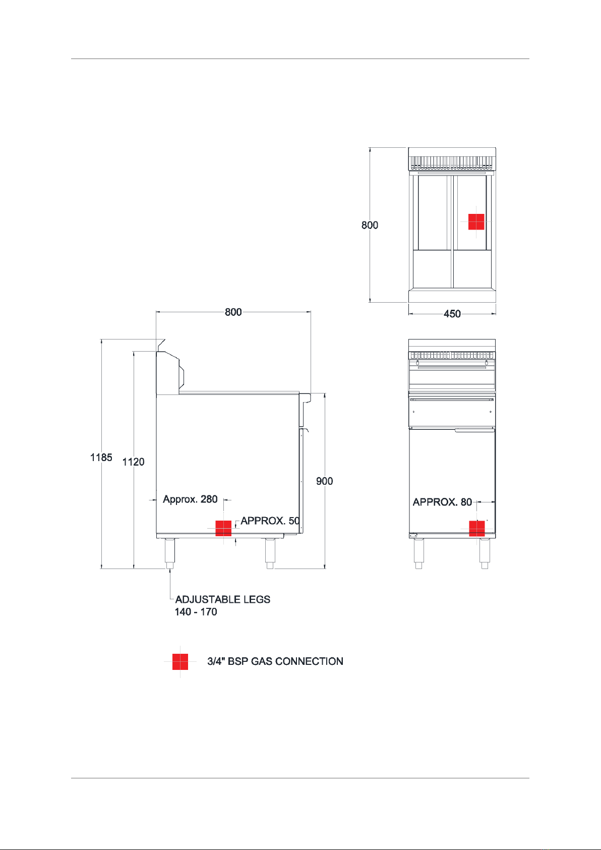
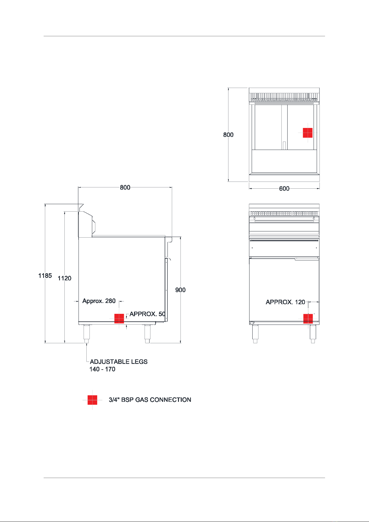
4. Connect the appliance to the gas supply. Location of the connection is shown in Dimensions
section 3 and is at the rear of the appliance with a ¾” B.S.P male fitting.
5. Ensure all gas connections are tight and free of leaks using appropriate gas detecting
equipment.
6. Bleed out any air in the lines.
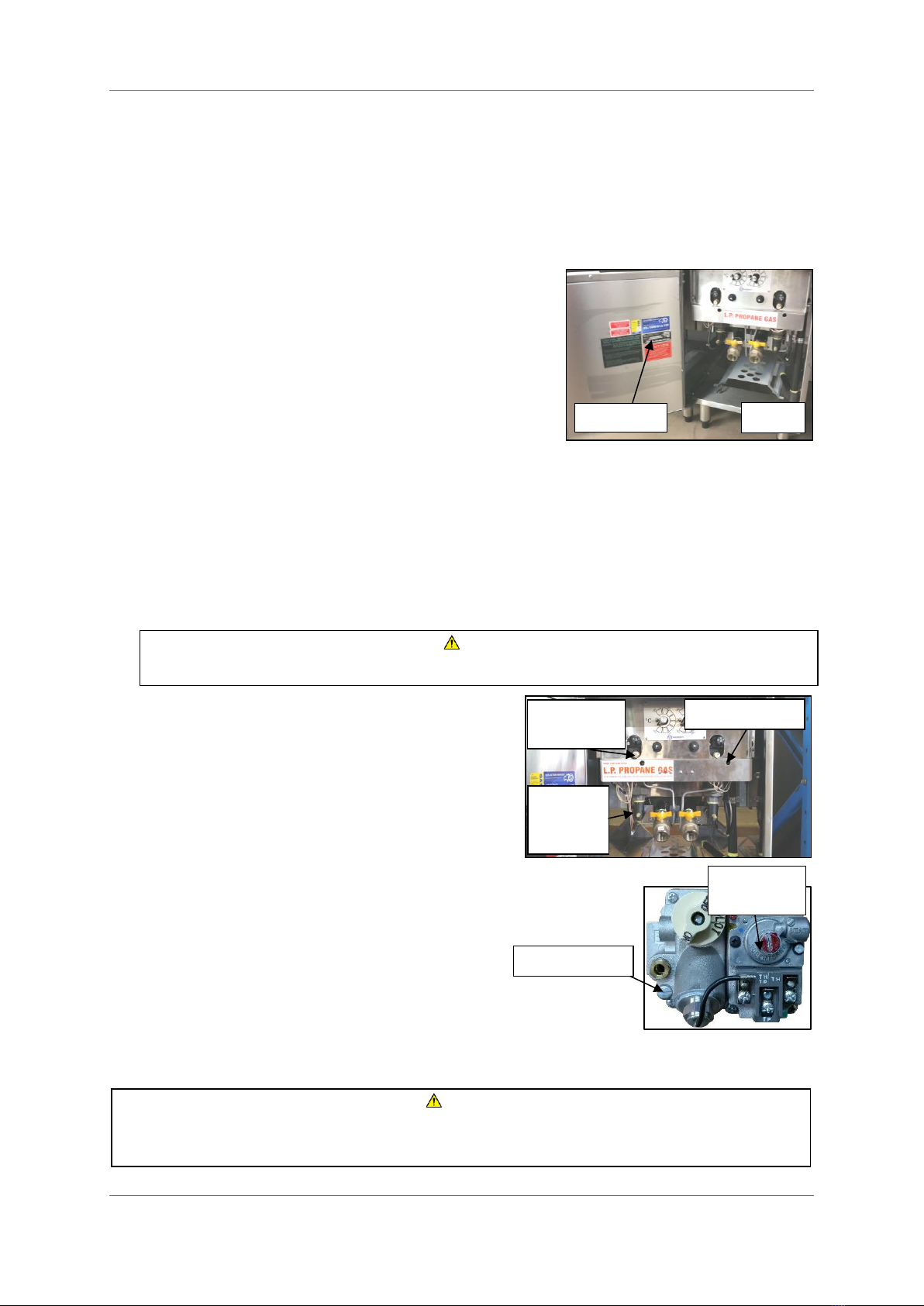
7. Fill the tank and then measure the appliance
operating pressure at the manifold test point
with the appliance running. If required, adjust
the pressure at the gas valve to the value shown
in Specifications section 3.3- Gas Supply
Requirements.
8. Although the pilot is set in the factory, check that
the pilot flame does not interrupt the main burner and ensure it
lights quickly. Final adjustments can be made through the pilot
adjustment hole.
Rating Plate
Img 1
Manifold
Pressure
Test Point
Pilot Adjustment
Gas Pressure
Adjustment
WARNING
Never use an open flame to detect gas leaks and ensure the tank is filled before operating
Pilot Adjustment
Gas Pressure
Adjustment
Alternative gas control valve

Installation
11
5.5 Commissioning
Once the appliance has been installed always ensure its functions are operating as per the following
check list. Refer to Operation in section 6 for further details on how to operate each control.
1. Remove any plastic coating from steel panels.
2. Ensure all gas connections are correct and tight.
3. Ensure all parts are in their correct positions e.g. scrap arrestor, base heat shield, baskets
and basket holder etc.
4. Turn on the gas and check for correct gas pressure as in Specifications section 3.
5. Turn on and check the pilot flame, sparker, thermostat, high-limit switch, gas control and
main burner are all operating correctly.
6. Instruct the operator on correct lighting procedures, filling and draining the oil, starting up
and shutting down the appliance.
5.6 Before First Use
Before initial start-up, clean the protective oil from the interior of the pan with washing soda
solution or other grease dissolving material. If required, the pan may be boiled using water and
detergent solution filled to the oil fill line on the fryer. Drain through the valve in the bottom then
rinse thoroughly. (Note: The tank must be completely rinsed out as even a small particle of cleaner
in the pan will ruin the cooking medium). Also, clean the baskets and strainer. Wipe the tank and all
components dry and ensure NO water remains.

Operation
12
1. Gas Control Valve
OFF Position
PILOT Position
ON Position
2. Thermostat
Temperature Range
A. 100°C - 200°C
B. 150°C - 190°C
3. High-Limit Switch
4. Sparker
5. Pilot Viewing Cavity
6. Oil Drain Valve
WARNING
Never operate this appliance with the fryer tank empty. Fill to the marked level on the tank as
instructed in this section.
6. Operation
6.1 Operational Controls
Flame failure protection and permanent pilots are fitted as standard on all Goldstein fryers as
required by local regulations and safety to the operator. If the pilot flame goes out, the flame failure
protection will shut off any gas to the burner. The permanent pilot allows for the appliance to go on
stand-by and the operator to continuously re-light the main burners without re-ignition.
Note: All gas control valves in this model have the same operation. Please follow the instructions
below on how to operate the controls.
6.2 Lighting the Pilot
1. Turn the gas control knob to the PILOT position. Push and hold the knob in while
simultaneously pressing the SPARKER button. Continue holding in the PILOT position for
approximately 10 seconds to establish the pilot flame.
2. If the pilot does not remain alight after 10 seconds, repeat step 1.
3. Ensure the pilot is lit through the viewing cavity then close the fryer door.
4. Note: After the burner and pilot has been completely turned off, to re-light the burners the
pilot must establish a flame to the power generator (thermopile) for up to 30 seconds
before the main valve can be switched on. If the valve is switched on prematurely and the
pilot flame goes out, re-light the pilot and wait 30 seconds before switching on the valve.
Control Panel A
Control Panel B
1
1
2A
2B
3
3
4
4
5
5
6
6

Operation
13
WARNING
Always completely shut down the fryer including the PILOT before draining oil from the tank.
Ensure the oil has cooled to a safe temperature before draining.
6.3 Filling the Tank with Liquid Shortening
1. Ensure that the oil drain valve is closed and the tank is free of any
residual moisture.
2. Place the scrap arrestor in the tank as shown.
3. Fill the fryer tank to the indicated level. It is recommended to fill
the oil slightly lower than desired. Once heated, the oil will
expand, raising the level slightly.
6.4 Filling the Tank with Solid Shortening
1. Break down the solid shortening and completely pack it into the
tank. Do not leave any large gaps and do not bend or damage the
sensor probes at the front of the tank. Damaging the probes will
cause the appliance to not function properly.
2. Once the shortening has been firmly packed, melt the shortening
by turning on the fryer. It is recommended to turn the burners on
for no more than 30 seconds at a time, at 2 minute intervals until
the shortening has liquefied. This ensures minimal stress to the fryer tank and does not
break down shortening life.
6.5 Turning on the Main Burner
1. Once the pilot is lit and the tank is filled, turn the gas control to the ON position.
2. Turn and select to the desired temperature on the Thermostat.
6.6 Turning off Main Burner and Pilot
1. Turn the gas control knob to the PILOT position to turn off the main burner. The pilot will
remain alight. During service while the fryer is not in use, it is recommended to keep the
pilot alight.
2. To completely shut down the main burner and pilot, push the gas control knob in and turn to
the OFF position and close the fryer door.
6.7 Draining the Oil
1. Shut the fryer down completely and wait until the oil has cooled down before draining.
2. If required, screw on the drain extension tube to the drain outlet. Open the drain valve and
empty the oil into either a filter or steel pan. Do not use glass or plastic containers.
Img 4
REMINDER
Keep the oil temperature in the fryer to a maximum of 180°C. Higher temperatures will cause
rapid breakdown of the oil and give no faster cooking. At 205°C to 210°C the life of the oil is
only one third of its life at 180°C. In addition, increased decomposition causes the oil to smoke
badly even if the temperature is lowered to 180°C again. High temperatures give no
advantages, increases cost and fire danger.

Cleaning and Maintenance
14
7. Cleaning and Maintenance
7.1 General
Build-up of grease, fat and carbon will impede effective heat transfer from the heat source to the
cooking medium. Keeping the fryer clean will ensure it operates correctly and efficiently.
7.2 During Service Cleaning
1. Skim the top of the oil frequently, particularly if breaded products or heavy batter is used.
2. Check and inspect the oil. If the fryer is under heavy use and requires filtering, shut it down
and filter the oil safely as instructed in Operation section 6.7.
3. Use the provided probing rod to remove any blockages or foreign matter in the drain valve.
7.3 After Service Cleaning
1. Drain and filter the oil and remove any matter left at the bottom of the tank with a nylon or
wooden scraper.
2. Wipe off any oil from exterior surfaces and clean with a suitable cloth and cleaning agent.
3. Remove and wash all removable parts i.e. baskets, basket holder, drain extension and scrap
arrestors.
4. The oil can be filtered and stored back into the fryer tank and covered with a night lid.
7.4 Periodic Cleaning
1. Drain and completely empty any oil from the fryer tank. Scrape away any excess oil and
debris using a nylon or wooden scraper.
2. Clean the tank with a good grade cleaner or fill it with hot water and a mild detergent. Bring
to a rolling boil, turn the heat down and let the mixture stand until deposits and/ or carbon
spots can be rubbed off with a brush.
3. Clean the exterior panels with a hot cloth or soft scrubbing brush and cleaning agent suitable
for stainless steel. For stubborn or encrusted deposits, soak the area with the cleaning agent
and hot water and use a wooden or nylon scraper to remove.
4. Scrub the tank walls, then drain and rinse with clean water.
5. Refill the tank with clean water and boil again.
6. Drain, rinse and dry thoroughly.
CAUTION
Never use wash hoses on this appliance. The appliance is not waterproof and caution is
advised when hosing down floors near this appliance. Appliance regulators are commonly
connected near the bottom of the appliance and water in this area can create blockages.
CAUTION
Do not use steel wool, abrasive materials or caustic detergents on this appliance. Do not use
metal knives, spatulas or any other metal utensils to scrape the fryer tank or stainless steel
surfaces. Use protective clothing for cleaning to avoid dangerous contact with hot surfaces.

Cleaning and Maintenance
15
7.5 Periodic Maintenance
Incorporating a regular maintenance schedule will optimise and keep services running efficiently.
Goldstein can provide an MIS (Machine Inspection Service) that delivers regular inspection and
maintenance to reduce problems before they occur. For more information or to setup an MIS,
please contact the nearest Goldstein branch.
•For optimum performance this appliance should be serviced every 12 months.
•If the burners appear to be ‘yellow tipping’ or there are unusual odours emitting from this
appliance, turn the gas off and contact Goldstein Eswood or authorised service agents.
•For service and spare parts contact Goldstein Eswood on 1800 013 123.
CAUTION
This appliance is intended for professional use and is only to be used by trained, qualified
personnel.
Installation, maintenance and repairs should be performed by an authorized Goldstein service
agent or other qualified personnel. Installation, maintenance or repairs by an unauthorized
and unqualified personnel will void the warranty.

Trouble-Shooting
16
8. Trouble-Shooting
Please refer to the following guide as reference to diagnose and repair some of the more common
problems encountered. Should a problem not listed arise, or in doubt, please contact Goldstein or an
authorised service agent.
Fault
Cause
Solution
Pilot does not light.
No gas to appliance.
Pilot injector blocked.
Air in gas line.
Turn on the gas isolation valve
and/ or check LP bottles are
not empty.
Contact Goldstein service.
Hold in pilot position for 30
seconds while attempting to
light.
Pilot lights but does not hold
when releasing gas control
knob.
Knob is released before
heating thermocouple.
Faulty thermocouple
Flame on pilot too small.
Wavy or uneven pilot flame.
Hold the knob in for at least 20
seconds.
Replace thermocouple.
Call Goldstein service.
Gas pressure too low.
Blocked injector.
Contact Goldstein service.
Check and minimise strong
draughts near the appliance.
Burner does not light.
Incorrect gas supply pressure.
Faulty gas control.
Contact Goldstein service.
Piezo sparker not lighting pilot
Sparker lead is loose, damaged
or faulty.
Faulty or cracked electrode.
Faulty piezo sparker.
Repair a loose connection or
replace the lead.
Replace the electrode.
Replace sparker.

Gas Conversion
17
9. Gas Conversion
1. a. (MTHVFG02) Rotate the thermostat knob in
alignment with the control panel cut-out then
undo the screws holding in the control panel and
remove. Do NOT remove or loosen the
thermostat knob when taking off the control
panel as this will cause the fryer temperature to
go out of calibration and will need to be re-
adjusted if removed.
b. (MTHRS205) Pull off the thermostat knob from
the bezel and then undo the fixing screws holding
the thermostat to the control panel.
2. Undo the manifold union. Undo the thermopile
wires and pilot tubes from the gas control for
easier access.
3. Remove the pilot assembly bracket from the
burner and replace the pilot injector with the
new appropriate type.
4. Undo the burner holding screws then the burner
can be dislodged by unhooking the rear bracket.
5. Remove the union and fit it on the new
appropriate burner. Apply new thread sealant
and compound on the union before fitting.
6. Re-attach the appropriate burner assembly to
the tank and manifold in reverse order.
9.1 Commissioning
1. Check all work for leakage using appropriate gas
detecting equipment.
2. Refer to section 4.6 Commissioning for a check list.
3. Replace the rating plate and any markings associated with the gas type with the appropriate
type.
WARNING
Gas conversion procedures should only be performed by an authorized Goldstein Eswood
service agent or qualified personnel. Unauthorized and unqualified personnel will void the
warranty. Gas isolator MUST be turned off before commencing any service work.
Knob Alignment
Img 5. a–MTHVFG02 thermostat
Img 5. b–MTHRS205 thermostat
Pilot Holding Screws
Burner
Holding
Screws
Burner
Bracket Clip
ATTENTION
Gas conversion is not complete until the appliance has been re-commissioned. Please refer to
the Installation section 5.5 Commissioning of this manual for details.
Pilot Adjustment
Img 6

Wiring Diagrams
18
10. Wiring Diagrams

Spare Parts
19
11. Spare Parts
11.1 Parts Diagram –All Models

Spare Parts
20
11.2 Parts List
ITEM No. CODE DESCRIPTION
1
GRG72M05
SINGLE PROBE ELEC SPARKER
1
ESP00008
PIEZO IGNITER (2014 ONWARDS)
1A
ESPVFG01
PIEZO SPARKER (PRE-2014)
2
ESPLVFG1
600mm SPARKER LEAD
3
MCK00005
LPG CONVERSION KIT
4
GCUVFG01
NOVA GAS CONTROL
4
GCUVFG01-1
ROBERTSHAW GAS CONTROL
5
MBKTGF00
STANDARD BASKET
6
FRV00T01
VFG1 BURNER
6A
FRV45T01
VFGT BURNER
6B
FRV60T01
VFG24 BURNER
7
FRV00M02
REFER DWG FRV00M02 FOR SIZES
8
FRV00T02
1 1/4" DRAIN PIPE
8A
FRV45T02
1” DRAIN PIPE
9
FRV00M04
VFG1 SCRAP ARRESTOR
9A
FRV45M04
VFGT SCRAP ARRESTOR
9B
FRV60M04
VFG24 SCRAP ARRESTOR
10
GTC10600
INTERRUPTOR THERMOCOUPLE
10
GTC00601
THERMOCOUPLE
11
GPGVFG01
THERMOPILE
12
GPIBVFG1
PILOT BODY
13
MTAC0032
1 1/4" BALL VALVE
13A
MTAC0025
1’’ BALL VALVE VFGT
14
MCA00007
DOOR MAGNET CATCH
15
STG00P36
DOOR HANDLE
16
FRV00P23
VFG1 BASKET HOLDER
16A
FRV45P23
VFGT BASKET HOLDER
16B
FRV60P23
VFG24 BASKET HOLDER
17
MFT00050
PLASTIC BULLET FEET
Other manuals for 800 Series
1
This manual suits for next models
3
Table of contents
Other goldstein Fryer manuals