Gopel Electronic basicCON 4121 Video Dragon User manual

GOEPEL electronic GmbH
Goeschwitzer Str. 58/60 •D-07745 Jena
+ 49-3641-6896-597 • ats_support@goepel.com • www.goepel.com
basicCON 4121
Video Dragon
User Manual
(Translation of Original docu)
Document Version 1.7

Issue: June 2022
© 2022 GOEPEL electronic GmbH. All rights reserved.
The software described in this manual as well as the manual itself are supplied under license
and may be used or copied only in accordance with the terms of the license.
The customer may make one copy of the software for safety purposes.
The contents of the manual is subject to change without prior notice and is supplied for information
only.
The hardware and software might be modified also without prior notice due to technical progress.
In case of inaccuracies or errors appearing in this manual, GOEPEL electronic GmbH assumes
no liability or responsibility.
Without the prior written permission of GOEPEL electronic GmbH, no part of this documentation
may be transmitted, reproduced or stored in a retrieval system in any form or by any means
as well as translated into other languages (except as permitted by the license).
GOEPEL electronic GmbH is neither liable for direct damages nor consequential damages from
the company’s product applications.
Printed: 29.06.2022
All product and company names appearing in this manual are trade names or registered trade names of their respective owners.

ble of Contents
basicCON 4121 –User Manual i
1INSTALLATION AND WARRANTY ..................................1-1
1.1 SCOPE OF DELIVERY...........................................................1-1
1.2 HARDWARE INSTALLATION ...................................................1-1
1.2.1
Connect the Video Dragon.......................................1-1
1.2.2
Module Change ......................................................1-2
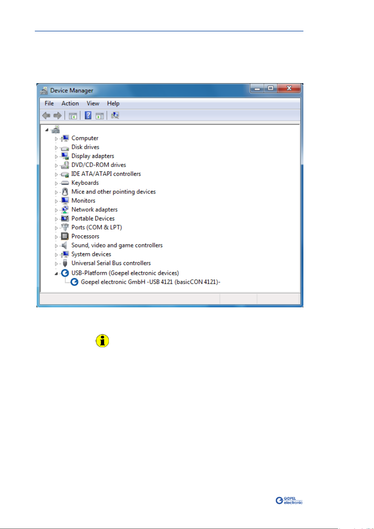
1.3 DRIVER INSTALLATION ........................................................1-3
1.3.1
USB .......................................................................1-3
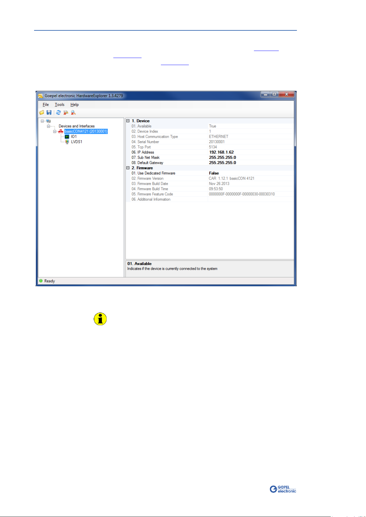
1.3.2
Ethernet.................................................................1-5
1.4 WARRANTY......................................................................1-7
1.5 EMC..............................................................................1-7
2VIDEO DRAGON HARDWARE .........................................2-1
2.1 GENERAL CHARACTERISTICS .................................................2-1
2.2 TECHNICAL DATA ..............................................................2-3
2.2.1
Dimensions ............................................................2-3
2.2.2
Electrical Characteristics ..........................................2-3
2.3 MAINBOARD.....................................................................2-4
2.3.1
Structure................................................................2-4
2.3.2
Connections ...........................................................2-5
2.3.3
Power supply..........................................................2-6
2.3.4
LEDs/ Status display ...............................................2-6
2.3.5
Addressing .............................................................2-7
2.3.6
LAN/ Ethernet ........................................................2-7
2.3.7
USB .......................................................................2-7
2.3.8
S/PDIF Output........................................................2-7
2.3.9
eSATA ...................................................................2-8
2.3.10
HDMI Output..........................................................2-8
2.3.11
UUT Supply ............................................................2-9
2.3.12
Digital IO/ CAN.....................................................2-10
2.3.13
Galvanic Isolation .................................................2-12
2.3.14
Video signal Routing .............................................2-12
2.4 MEDIA INTERFACE MODULES ..............................................2-15
2.4.1
Overview .............................................................2-15
2.4.2
INAP375T ............................................................2-19
2.4.3
INAP375R ............................................................2-21
2.4.4
INAP375T MII ......................................................2-23
2.4.5
INAP375R MII ......................................................2-25
2.4.6
DS90UB947..........................................................2-28
2.4.7
DS90UB948..........................................................2-30
2.4.8
DS90UB925..........................................................2-32
2.4.9
DS90UB926..........................................................2-34
2.4.10
DS90UB913A........................................................2-37
2.4.11
DS90UB914A........................................................2-39
2.4.12
DS90UB905..........................................................2-41
2.4.13
DS90UR906..........................................................2-43
2.4.14
MAX9275 .............................................................2-45
2.4.15
MAX9276 .............................................................2-47
2.4.16
MAX9271 .............................................................2-49
2.4.17
MAX9272 .............................................................2-51
2.4.18
MAX9259 .............................................................2-53
2.4.19
MAX9260 .............................................................2-55
2.4.20
MAX9247 .............................................................2-57
2.4.21
MAX9248 .............................................................2-59
2.4.22
ADV7611..............................................................2-61
2.4.23
RGB888T .............................................................2-63
2.4.24
RGB888R .............................................................2-65

Table of Contents
ii basicCON 4121 –User Manual
3VIDEO DRAGON –FIRST STEPS ....................................3-1
3.1 ASSEMBLY OF THE SYSTEM................................................... 3-1
3.2 DEVICE REGISTRATION .......................................................3-2
3.3 CONFIGURATION ...............................................................3-3
3.4 CAPTURING .....................................................................3-5

Installation and Warranty
basicCON 4121 –User Manual 1-1
1Installation and Warranty
1.1 Scope of Delivery
The following parts belong to a delivery of your GOEPEL electronic
Video Dragon basicCON 4121:
1x Video Dragon basic device
1x Media Interface Module
(according to your order, already installed)
Power supply Unit
CD with Driver, Software and Manual
LAN cable
USB cable
Video cable
(the type depends on the installed Media Interface Module)
1.2 Hardware Installation
Having unpacked your Video Dragon completely, please check
whether the type of the Media Interface Module corresponds with your
order.
Then check if the module is fixed mounted at the Video Dragon.
Please make absolutely certain that all of the hardware installation
procedures described below are carried out with your system
switched off.
We recommend to install/ update the device driver software for USB
before connecting the Video Dragon to the PC/ Laptop
(see Driver Installation/ USB).
Hardware installation for Video Dragon basicCON 4121 means only to
connect the attached power supply unit to the Power socket
(see Figure 2-4), and the USB or Ethernet cable to the control PC/
Laptop.
Please use the supplied USB cable to connect your Video Dragon to
the USB interface of the PC/ Laptop.
Other cables may be inapplicable.
Then, connect the Media Interface Module of the Video Dragon to the
device to be tested (the UUT).
All other connections are not required for video transmission.
Please use them only when needed.
Look for a description of these interfaces in chapter Mainboard.
1.2.1 Connect the
Video Dragon

Installation and Warranty
1-2 basicCON 4121 –User Manual
Media Interface Modules enable your Video Dragon to perform a
multitude of different Test tasks; and they are compatible to diverse
systems. Therefore it can be required to install a new Media Interface
Module for a new Test task.
Please make absolutely certain that all of the hardware installation
procedures described below are carried out with your system
switched off.
Please proceed as follows to change a Media Interface Module:
To remove an already installed module, loosen both knurled
screws (see figure below) completely. Then extract the module
from the Video Dragon by touching it at the knurled screws.
Plug the new module into the Video Dragon (within the guide
rails, that way that all labels have the same direction). Press
the module finally with a little power to the inside connector.
Then fasten manually both knurled screws.
1.2.2 Module
Change
Figure 1-1:
Module change

Installation and Warranty
basicCON 4121 –User Manual 1-3
1.3 Driver Installation
To install the GOEPEL electronic USB drivers on your system, execute
the G-USB driver setup.
For this, start the
G-USB-Setup-*.exe
setup program (the asterisk
stands for the version number) of the delivered CD, and follow the
instructions.
Your Video Dragon basicCON 4121 can be operated under Windows®XP
as well as under Windows®7/ 32 Bit and Windows®7/ 64 Bit.
Before connecting the Video Dragon basicCON 4121 stand-alone
hardware to a USB port of your PC/ laptop, please ensure that the
external power supply of the device is connected and ready for
operation (Video Dragon’s hardware can NOT be supplied via USB).
Then, connect the device by the supplied USB cable to a USB port of
your PC or laptop (see Hardware Installation).
Due to the plug and play capability of Windows®, the operating
system will recognize the device automatically. As soon as it has been
detected, Windows®informs you with the “Found New Hardware
wizard” and guides you through the device driver installation process.
Select the “Install the software automatically (Recommended)” option
and click “Next” to continue.
On completion of the installation process, Windows®will request you
to reboot your computer.
For safe and reliable operation this step is strongly recommended.
1.3.1 USB

Installation and Warranty
1-4 basicCON 4121 –User Manual
After the installation, you can check by the Windows®Device Manager
whether the unit is properly embedded by the system.
As an example, the following figure shows the successful embedding
of one basicCON 4121 device:
Figure 1-2: An installed basicCON 4121 in the Windows
®Device Manager
Please note that the Device Manager shows ALL USB controllers
supported by this driver.

Installation and Warranty
basicCON 4121 –User Manual 1-5
If the Ethernet interface is used for communication with the control PC
or laptop, there is no driver installation required.
Nevertheless, to address the Video Dragon basicCON 4121, you need a
network device that is set up with a valid IP Address and proper
subnet mask. Otherwise the control PC or laptop will not be able to
communicate with the basicCON 4121 in the network.
This setup needs to be done only once, independent of the number of
basicCON 4121 devices you are willing to use.
For setting up, you have to open the Network Connection Properties
dialog of the appropriate network device:
Select the “Internet Protocol Version 4 (TCP/IPv4)” properties.
A new window opens where you set the IP Address and subnet mask
to fixed values (i.e., your Video Dragon has a static IP Address)
regarding the following rules:
The IP Address of the network device has to be different
from that of the basicCON 4121.
The subnet mask has to be set to such a value,
that both IP Addresses (of network device and basicCON 4121)
are in the same subnet.
Example:
The default IP Address of the basicCON 4121 is 192.168.1.62.
You can set up your network device for example to the IP Address
192.168.1.100 and the subnet mask to 255.255.255.0, since both devices
are now in the same subnet 192.168.1.xx.
1.3.2 Ethernet
Figure 1-3:
Network Connection
Properties

Installation and Warranty
1-6 basicCON 4121 –User Manual
If the network device has been set up right, after the Hardware
Installation, the Video Dragon can directly be addressed via the IP
Address (see also Addressing).
This IP Address can be changed by the HardwareExplorer.
The newly set IP Address becomes effective after a restart of your
Video Dragon.
Figure 1-4: IP Address in the GOEPEL electronic HardwareExplorer
Changing the static IP Address is required then if you want to
operate several Video Dragon devices in the same network.
In this case, always connect initially only the device for that you
have to change the IP Address.
Then change the corresponding IP Address.
If all Video Dragon devices have different IP Addresses, you can
operate them jointly in the same network.

Installation and Warranty
basicCON 4121 –User Manual 1-7
1.4 Warranty
Warranty Conditions
GOEPEL electronic GmbH guarantees the Test system’s faultlessness for
24 months, beginning with its delivery.
Warranty is NOT granted for faults resulting from inappropriate use,
modifications or unintended use.
Designation of Warranty cases
We may ask you to designate cases of warranty clearly. Repairing
orders without the notification of a warranty claim are initially
executed with costs.
Of course, we repair your Test system if necessary even in the case
our warranty duty has expired, after submitting an offer and your
order.
1.5 EMC
To meet the required conditions of Electromagnetic compatibility, the
Test system may only be operated in the as-delivered condition.
Mechanical or electrical modifications, regardless of type, are not
permitted.


Hardware
basicCON 4121 –User Manual 2-1
2Video Dragon Hardware
2.1 General Characteristics
Video Dragon basicCON 4121 is a GOEPEL electronic GmbH test system
with USB 3.0 and Gigabit Ethernet Interface to transmit or receive
video data. The test system has been especially adapted to the
requirements and transmission standards of the automotive industry.
This way, in addition to the video data, also audio data and control
data can be handled.
The Video Dragon stands out by its easily changeable Media Interface
Module, by that the system can be quickly adapted to current test
tasks. So, the Video Dragon is transformed to a Frame Grabber from a
Frame Generator or vice versa by a few actions only. Moreover, it
supports a multitude of different transmission standards.
With this, the GOEPEL electronic Video Dragon is optimally prepared for
executing present and future Test tasks.
The following performance characteristics make the Video Dragon to
be an extremely multifunctional Video test system:
High-Performance ARM Cortex A8 Processor
with three Video Coprocessors
1 GByte DDR3 operating memory
128 MByte NAND Flash
USB 3.0 and Gigabit Ethernet interfaces for control and data
exchange with the PC (see USB and LAN/ Ethernet chapters)
HDMI 1.3 compatible Monitor output for checking the live
stream of the video data, and with this also for the
configuration of the entire test structure
(see HDMI Output chapter)
external SATA II interface to connect external mass storage
devices (see eSATA chapter)
S/PDIF Audio output for checking Audio data
(see S/PDIF Output chapter)
Media Interface Slot for inserting a Media Interface Module for
the technical system adaptation to the test object
(see Media Interface Module chapter)
Currently available Media Interface Modules
support the APIX, FPD-Link, GMSL and HDMI standards for
transferring video, audio or control data
Universal, digital IO interface for triggering or status output
as well as for the interaction with test objects
(see Digital IO/ CAN chapter)
CAN interface for configuration or restbus simulation of the test
environment (see Digital IO/ CAN chapter)
Status Visualization by four LEDs
(see LEDs/ Status display chapter)
Real Time Clock for time synchronization
0°C …+55°C operating temperature range
(with passive cooling)

Hardware
2-2 basicCON 4121 –User Manual
Video Dragon basicCON 4121 is a stand-alone device to be connected to
a PC or laptop. It was developed for applications out of complex test
systems.
Figure 2-1:
Video Dragon –Front view
Figure 2-2:
Video Dragon –Rear view

Hardware
basicCON 4121 –User Manual 2-3
2.2 Technical Data
(Length x Width x Height):
203mm x 172mm x 66mm (without Media Interface Module)
216mm x 172mm x 66mm (with Media Interface Module)
The following table shows the electrical characteristics of the device-
specific interfaces (without mentioning the standardized interfaces like
HDMI, Ethernet, USB, eSATA and S/PDIF as well as the interfaces
depending on the Media Interface Module; these are described in the
Media Interface Modules chapter).
Symbol
Property
Min.
Typ.
Max.
Unit
Annotation
Power supply
VSS
Supply voltage
7
12
28
V DC
ISS
Supply current
1200
1600
mA
at 12V DC
PSS
Power consumption
20
W
Digital Inputs
N
Number
4
VIH
High level input voltage
2.3
28
V
UIL
Low level input voltage
0.8
V
fMAX
Maximal switching frequency
1
MHz
at 28V
Digital Outputs
N
Number
6
VOH
High-level output voltage
5
27
V
Depends on VBat
(ext. Vsupply)
IO
Output current
10
mA
per channel
fMAX
Maximal switching frequency
10
kHz
at 28V
UUT Supply (optionally)
UUUT
UUT Supply Voltage
22
V DC
IUUT
UUT Supply Current
1000
mA
CAN / CAN FD (optionally)
C
Transmission rate
5
MBaud
at High Speed
VBATint
Internal battery voltage
12
V
disengageable
VBAText
External battery voltage
27
V
depending on the
transceiver
RA
Terminating resistor
High Speed transceiver
120
Ω
disengageable
RA
Terminating resistor
Low Speed transceiver
10
kΩ
2.2.1 Dimensions
2.2.2 Electrical
Characteristics

Hardware
2-4 basicCON 4121 –User Manual
2.3 Mainboard
By its open hardware concept (see Figure 2-3), the GOEPEL electronic
Video Dragon basicCON 4121 with its changeable Media Interface Module
and the following FPGA is optimally prepared for executing a multitude
of current and future test tasks.
Video Dragon consists of a mainboard in a passively cooled box and a
changeable Media Interface Module supporting the different
transmission standards. So the Media Interface Module offers the
possibility that the Video Dragon acts as a transmitter or receiver of
Multimedia data. The focus of the supported Standards concentrates
clearly on the automotive industry.
There are two Module classes, which have influence over the
functionality and the flow of data of the Video Dragon.
By a “Generator Module”, the Video Dragon becomes a transmitter/
generator of Multimedia data. This can be used, for example, for the
output of stored pictures or videos to check a connected display.
The “Grabber Module”converts the Video Dragon to a receiver of
Multimedia data, for checking the functionality of Video sources, for
example DVD players or combi-instruments.
Moreover, “Grabber Modules” can route through the received data to
the real receiver (a display, for example). Thereby the system
structure has not to be changed.
The Video Dragon automatically detects the inserted Module and its
type and preconfigures itself accordingly.
Each Media Interface Module contains a special IC different from the
others required for the corresponding transmission standard. Generally
the Video Dragon supports all functions for video, audio and data
transmission offered by the corresponding IC.
Output
HDMI
Out
LAN
eSATA
Media
Interface
Modul µC
FPGA
NAND
128MB DDR3
1GB
Digital IO
Input
USB
USB3.0
Controller
ETH PHY
Driver
CAN
CAN
TRX
S/PDIF
Out
RT
Clock
Status 1..4
Power
UUT Power In
The components on Video Dragon’s mainboard are identical for
Generator operation as well as for Grabber operation.
Please find more information in the following chapters.
2.3.1 Structure
Figure 2-3:
Video Dragon –
Block diagram

Hardware
basicCON 4121 –User Manual 2-5
The following two figures show all connections of the Video Dragon:
(1) Power
Power supply input (7 to 28V DC)
(2) IP Reset
Reset button for resetting the IP address
(3) LAN
Gigabit Ethernet connector for connection to the control PC
(4) USB
USB connector for connection to the control PC
(5) S/PDIF Out
S/PDIF output for audio recording with external devices
(6) eSATA
eSATA II connection to connect an external hard disk
(7) HDMI Out
HDMI 1.3 output for monitor connection
or for video recording by external devices
2.3.2 Connections
Figure 2-4:
Connections –Rear side
1
2
3
4
5
6
7

Hardware
2-6 basicCON 4121 –User Manual
On the front side, you find the following elements:
(8) UUT Power In
UUT Supply –depending on the Media Interface Module
(9) Digital IO/ CAN
15-pole DSUB socket for connecting the digital I/Os as well as
the integrated CAN bus
(10) Media Interface
Media Interface Module included in the Media Interface Slot
(11) Status
four Status LEDs
Power supply of the Video Dragon is provided via the Power (1)
connector by a coaxial power plug (2.1 x 5.5mm/ plus polarity inside).
The device can be supplied via the delivered power supply unit or an
own voltage source.
The range of the supply voltage should be between 7 and 28V DC, the
provided power should be 20 Watts at least.
The LEDs (11) indicate the current operating status of the Video
Dragon according to the following table:
LED1
LED2
LED3
LED4
Annotation
Alternately blinking
Bootloader software runs
blinking
Firmware runs
ON (shortly)
Execution of a Firmware command
ON
Ethernet connection established
ON
Video output active (Generator mode)
Video lock active (Grabber mode)
Figure 2-5:
Connections –Front side
2.3.3 Power supply
2.3.4 LEDs/
Status display
9
10
11
8

Hardware
basicCON 4121 –User Manual 2-7
The Video Dragon has an Ethernet and a USB interface, alternatively
used for the control. Addressing for several connected devices is
effected as follows:
In the case the Ethernet interface (3) is used, the device can be
addressed by the Default IP Address 192.168.1.62, Port 5134
(see chapter Ethernet). If you want to operate two or more devices in
the same network, then their IP Addresses have to be changed. For
this, connect always one device to the Video Dragon and change the
corresponding IP Address.
Generally, there are two ways for this:
HardwareExplorer: Select the Video Dragon device,
under Device set the required IP Address;
the new IP Address is active after restart
G API command G_Common_Ethernet_IpAddress_Set;
the new IP Address is active after restart
This procedure is required for all devices. Please do not forget to write
down the new IP Addresses and the belonging Serial numbers.
Only when all devices have different IP Addresses, you can operate
them jointly in the same network.
Addressing via USB (4) is effected exclusively via the serial numbers:
The device with the LEAST serial number is always the device with
the number 1(that means, DeviceNumber = 1.)
For configuration and control, a PC or laptop can be connected to the
Video Dragon by a standard network cable (CAT-5e or better) via the
RJ45 socket LAN (3).
The Video Dragon is compatible to networks of type
10/100/1000Base-T,
and it supports the IEEE 802.3, 802.3u and 802.3ab standards.
For configuration and control, a PC or laptop can be connected to the
Video Dragon also via USB.
For this, a cable with USB B plug has to be connected to the USB
socket (4).
You may use a USB2.0 cable as well as a USB3.0 cable, as both
Standards are fully supported.
To be able to output/ record audio data received or transmitted by the
Media Interface Module via an external audio sink (for example a sound
system) plug a coaxial cable with cinch plug to the S/PDIF Out audio
output (5).
The cable should have an impedance of 75 Ohms. It can be connected
to any digital audio input (S/PDIF).
2.3.5 Addressing
2.3.6 LAN/ Ethernet
2.3.7 USB
2.3.8 S/PDIF Output

Hardware
2-8 basicCON 4121 –User Manual
By means of the Video Dragon, input data can be recorded, and output
data can be buffered on an externally connected hard disk.
Thereby, the Video Dragon can be operated without a control PC.
Hard disks of SATA I/II/III types can be connected. But best
performance results when connecting a SATA II type hard disk, as the
interface is designed for that.
The connector is an 11 pole eSATAp plug, providing also the supply of
the connected hard disks additionally to the SATA interface. But only
hard disks with 5V DC voltage and a maximal current consumption of
350mA can be supplied (usually 2.5” devices.
The eSATAp connector combines a USB plug, whereby the hard disk is
supplied, with an eSATA connector for data transmission.
The pin assignment is as follows:
1 2 3 4567891011
USB
eSATA
Pin
Signal
Pin
Signal
1
5V DC
5
Ground
2
not connected
6
A+TX
3
not connected
7
A-TX
4
Ground
8
Ground
9
B-RX
10
B+RX
11
Ground
For the display of video data live streamings received or transmitted
by the Media Interface Module, a monitor can be connected to the HDMI
Out (7) video output of the Video Dragon.
2.3.9 eSATA
Figure 2-6:
eSATAp Plug structure
2.3.10 HDMI Output
Table of contents
Popular Test Equipment manuals by other brands

Tektronix, Inc.
Tektronix, Inc. TLS 216 user manual

Viavi
Viavi T-BERD/MTS 5800 Quick Card User Guide

Pittsburgh
Pittsburgh 93547 Instructions and precautions

Agilent Technologies
Agilent Technologies 54830 Series Service guide

LeCroy
LeCroy LC Series Operator's manual

Huazheng
Huazheng HZ-384A instruction manual