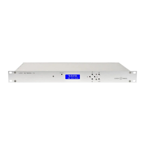
Gorgy Timing LEDI NETWORK TDS V1 User manual

MDE-LEDI-NETWORK-TDS-4099V2.0
1
LEDI
®
NETWORK TDS V1
LEDI
®
NETWORK TDS GPS
RAIL DIN TH35
TIME SERVER
USER MANUAL

2
MDE-LEDI-NETWORK-TDS-4099V3.0
WARNING! The following section provides the safety instructions for installation.
Please read it carefully before installing your device.
To protect your device, plug it into a grounded outlet.
The device must be connected to an electrical installation which is in accordance with
the NF C15-100 standard.
The wiring installation must include an easily accessible breaking device (circuit
breaker or disconnecting switch). This device must withstand the nominal voltage and
current values indicated on the device.
In Europe: in accordance with European regulations on the protection of individuals
and the environment, it is your responsibility to dispose of this equipment at a collection
site designed for this purpose (separately from household waste). For further
information, contact your reseller, your collection site or the relevant local authorities.
Any modification or opening of the product without the consent from the Customer
service department will void the warranty.
The LEDI® NETWORK TDS must only be installed, maintained and handled by
competent and knowledgeable persons.
All maintenance operations must be carried out with the power off, including for
systems connected to any relay outputs.
As a general rule, to avoid any interferences, the power (230V supply) and signal (time
information) cables must not be too close to each other. (keep a few centimetres apart)
CAUTION!After unpluggingthe LEDI®NETWORKTDS, thereis a risk of electric shock
from the power connector/plug socket for up to 2 seconds.
To avoid the risk of electrical interference, position the LEDI® NETWORK TDS as far
as possible from sources of radiation (Loudspeakers, antennas, high-frequency
equipment, electromagnetic alarms…).
Gorgy Timing disclaims all liability in the event of accident or damage caused by
improper use of LEDI® NETWORK TDS.
All GORGY TIMING products comply with the following standards: CE, EN60950-1,
EN55022 class B, EN50024.
IMPORTANT SAFETY INSTRUCTIONS

MDE-LEDI-NETWORK-TDS-4099V3.0
3
ENGLISH
General hazard –there is a risk of damage to the product if instructions are not followed
Electrical hazard –there is a risk of electrocution or personal injury if instructions are not
followed.
Equipment fully protected by double insulation.
Warnings
Please follow the precautions and instructions indicated below in order to ensure the safety of you and
your environment, and to prevent any potential damage to your device.
WARNING: An isolating switch in compliance with EN60947 standards is used as a
disconnecting device. It must be easily accessible and installed close to the power supply. It
must disconnect all active poles.
The LEDI® NETWORK TDS is intended for indoor use only, at an altitude of less than 2000
metres.
Waste disposal by users in private households within the European Union
This symbol on the product or its packaging indicates the product must not be disposed of with
your general household waste. Instead, it is your responsibility to dispose of your waste by
taking it to a designated collection point for the recycling of electrical and electronic appliances.
The separate collection and recycling of your waste contributes to the conservation of natural
resources and helps to ensure that recycling is environmentally and health friendly. For more
information about your nearest recycling centre, pleasecontact the shop where you purchased
your device, the household waste disposal services or your local authorities.
Technical features
TDS v1
TDS GPS Rail Din TH 35
Power supply
Voltage
110-250 Vac
18-72 VDC
Frequency
50-60Hz
Maximum current
0.1-0.2 A Max
Dimensions
Length
482 mm
209 mm
Width
266 mm
136 mm
Height
44 mm
73 mm
Operating conditions
Maximum operating temperature
50°C
55°C
Humidity (non-condensed)
90 %
EXPLANATION OF SAFETY SIGNS ON THE PRODUCT

4
MDE-LEDI-NETWORK-TDS-4099V3.0
CONTENTS
CONTENTS..........................................................................................................................4
1. INTRODUCTION........................................................................................................7
1.1. LEDI® NETWORK TDS V1 RACK....................................................................................7
1.2. LEDI® NETWORK TDS GPS –RAIL DIN TH35................................................................9
1.2.1. Version < 100m cable (solution with antenna GPS converter Part Number: 3Gxx)10
1.2.2. Version > 100m cable (solution with RTBGPS Part number: 4048/xx)).................10
A. RTB GPS antenna (part number: RTBGPS-4080) ................................................12
2. QUICKSTART .........................................................................................................13
2.1. PRODUCT CONNECTION..............................................................................................13
2.2. MANUAL NETWORK CONFIGURATION........................................................................14
2.3. TIME OUTPUT CONFIGURATION..................................................................................14
2.4. ALARM CONFIGURATION .............................................................................................14
3. GENERAL INFORMATION .....................................................................................15
3.1. TIME ZONES ..................................................................................................................15
3.2. LEAP SECOND...............................................................................................................16
3.2.1. Definitions............................................................................................................16
3.2.2. Protocols incorporating a leap second..................................................................16
3.2.3. LEDI®Network TDS performance.........................................................................16
3.2.4. Configuration recommendations...........................................................................17
3.3. SYNCHRONISATION CONCEPTS .................................................................................17
3.4. NOTIONS OFTHENTP PROTOCOL...............................................................................18
3.4.1 Client/Server mode ...............................................................................................19
3.4.2. Broadcast mode...................................................................................................20
3.5. TIME SERVER STATUS.................................................................................................20
3.6. SNMP (SIMPLE NETWORK MANAGEMENT PROTOCOL) AND MIB (MANAGEMENT
INFORMATION BASE)...........................................................................................................21
3.7 TIME INPUT INSTABILITY DETECTION..........................................................................23
4. FRONT LCD DISPLAY............................................................................................24
4.1. LIGHTS AND BUTTONS.................................................................................................24
4.2. STARTUP .......................................................................................................................25
4.3. TIME DISPLAY................................................................................................................25
4.4. ALARM DISPLAY............................................................................................................26
4.5. IPV4 / IPV6 CONFIGURATION........................................................................................28
4.5.1. Display current IP addresses................................................................................28

MDE-LEDI-NETWORK-TDS-4099V3.0
5
ENGLISH
4.5.2. Menu....................................................................................................................28
4.5.3. IPv29....................................................................................................................29
4.5.4. IPv6 .....................................................................................................................31
4.6. RESTARTING................................................................................................................33
5. WEB INTERFACE...................................................................................................34
5.1. PRESENTATION.............................................................................................................34
5.2. DESCRIPTIONOF WEB PAGES ....................................................................................35
5.2.1. Navigation menu..................................................................................................35
5.2.2. "Index" Page ........................................................................................................38
5.2.3. "Network" Page....................................................................................................40
5.2.4. "Alarms" Page......................................................................................................43
5.2.5. "SNMP" Page.......................................................................................................45
5.2.6. "NTP" Page..........................................................................................................48
5.2.7. NTP Server Statistics Page..................................................................................54
5.2.8. "Input" Page.........................................................................................................55
5.2.9. "Output" page.......................................................................................................59
5.2.10. "Interface" Page.................................................................................................64
A. User Accounts ......................................................................................................64
B. Front LCD.............................................................................................................65
C. Other interfaces....................................................................................................66
D. File system...........................................................................................................68
E. SNMP Interface....................................................................................................69
F. Telnet and SSH Interface......................................................................................70
G. Command prompt.................................................................................................70
H. File transfer..........................................................................................................74
I. "Restart" Button .....................................................................................................74
5.2.11. Update...............................................................................................................75
5.2.12. "Diagnostics" Page.............................................................................................78
6. APPENDIX A –CONNECTIONS.............................................................................81
6.1. INSTALLATION VIEW.....................................................................................................82
6.2. DCF-GPS ANTENNA ......................................................................................................84
6.2.1. DCF Antenna.......................................................................................................84
6.2.2. GPS antenna (converter unit)...............................................................................85
6.3. AFNOR-NFS-87500 / IRIG-B OUTPUT ...........................................................................86
6.4. SERIAL IMPULSION OUTPUT........................................................................................86
7. APPENDIX B –OUTPUT CODES FORMAT ..........................................................87
6
MDE-LEDI-NETWORK-TDS-4099V3.0
7.1. AFNOR/IRIG-BNFS87500 ..............................................................................................87
7.2. DESCRIPTION OF DCF AND TDF TIME CODES...........................................................90
7.3. POLARISED MINUTE PULSES ......................................................................................92
8. APPENDIX C –MAINTENANCE.............................................................................94
8.1. CARD REPLACEMENT +IMPULSION CARD POWER SUPPLY....................................94
8.2. MICROCONTROLLERS REPLACEMENT.......................................................................95
8.3. OUTPUT CARDS ADDRESSES SWITCHES..................................................................96
8.4. TOP AND IRIG-B DCLS TIME CODE OUTPUT SIGNALS..................................................97
8.5. SUPERVISION PROTOCOLS.........................................................................................98
8.5.1. Syslog messages catalogue...................................................................................98
9. APPENDIX D –TROUBLESHOOTING...................................................................99

MDE-LEDI-NETWORK-TDS-4099V3.0
7
ENGLISH
1. INTRODUCTION
This document is the instruction manual for the LEDI®NETWORK TDS V1 and the LEDI®
NETWORK TDS GPS Rail Din TH 35. These products are accurate and easily configurable
time servers.
Each server communicates through the following network protocols:
►IPv4 et IPv6
►HTTP(S)
►SNMP v1, v2c, v3
►Telnet
►SSH
►FTP
►SMTP
►Syslog
►(S)NTP
►ENDMI (to detect Gorgy Timing
products on the IP network)
Security features ensure that the server delivers reliable and continuous timing information.
1.1. LEDI® NETWORK TDS V1 RACK
The server synchronises through an NTP Ethernet 10/100 base T or DCF or GPS time input.
In case of a DCF or GPS input, the heart of the time base is a temperature-compensated
quartz oscillator (TCXO) which limits deviation when the time source is unavailable.
There are 3 available time outputs: AFNOR NFS 87500 / IRIG B, IMPULSION, NTP.

8
MDE-LEDI-NETWORK-TDS-4099V3.0
The use of the LEDI® Network TDS V1 has several advantages:
►Ethernet + IPnetwork interfacing.
►Simplified installation.
►Easy remote configuration and diagnostics.
►1U 19” rack easily mounted in many installations.
►3 configurable outputs:
- AFNOR NFS 87500 / IRIG-B
- NTP (V2, V3, V4): Unicast, Multicast et Broadcast
- Minute Impulses 24V //
ASSEMBLY
The rack must be fixed in a 19'' frame using 4 screws and cage nuts, shown in the image
below. (Screw 10-32 M6, tightening torque: 1.13Nm).
BOX CONTENTS
The box should contain the following items
►The 19" 1u rack, with the words "LEDI® NETWORK TDS" on the front panel
NOTE: The device code and configuration can be checked on the identification label on the
bottom or back of the device. It must correspond to the following number: 94031/opt (opt
depending on the device options).
►A non-locking IEC 60320 C13 mains power cable
NOT: only for models with alternative current (AC) supply.
►A 2-pin connector for DC power input
NOTE: only for DC models.
►One RJ45 network cable
►A DVD containing software and documentation
☛Please contact customer service if an item is missing

MDE-LEDI-NETWORK-TDS-4099V3.0
9
ENGLISH
1.2. LEDI® NETWORK TDS GPS –RAIL DIN TH35
The time server has GPS synchronisation input providing SNMP supervised NTP time
synchronisation.
Both an alarm visible on the front LED display and quick configuration from the front panel
buttons are available.
209 x 73 x 136 mm (WxHxD)

10
MDE-LEDI-NETWORK-TDS-4099V3.0
1.2.1. Version < 100m cable (solution with antenna GPS converter Part Number: 3Gxx)
MOUNTING
Fixing by rear panel in Rail Din (see image below).
►Kit contents (cable and GPS antenna not included):
- LEDI®Network TDS Rail Din
- One RJ45 network cable
- A DVD containing software and documentation
☛Please contact customer service if an item is missing.
►Power supply:
Direct current (DC) supply 24Vdc (18-72Vdc) on screw terminal block –10W max
1.2.2. Version > 100m cable (solution with RTBGPS Part number: 4048/xx))
►Mounting:
Rear panel mounting in Rail Din
Antenna to be positioned on the roof of the property and cable (not included) to be
routed to the time server. See reference table for model selection (IRIGB input).

MDE-LEDI-NETWORK-TDS-4099V3.0
11
ENGLISH
►Contents of kit (cable and RTB GPS antenna not included):
- LEDI®Network TDS Rail Din (RTB GPS),
- One RJ45 network cable
- A DVD containing software and documentation
☛Please contact customer service if an item is missing
►Power supply:
Continuous power supply 24Vdc (18-72Vdc) on screw terminal block –10W max

12
MDE-LEDI-NETWORK-TDS-4099V3.0
A. RTB GPS antenna (part number: RTBGPS-4080)
The RTB GPS generator is a GPS (Global Positioning System) satellite system receiver
device delivering time in IRIG B or AFNOR NFS 87500 code.

MDE-LEDI-NETWORK-TDS-4099V3.0
13
ENGLISH
2. QUICKSTART
2.1. PRODUCT CONNECTION
It is strongly recommended to make a note of the serial number (written on the identification
label), the location and a brief description of the device. The table in Appendix A - 6.1
Installation View can be used for this purpose.
►Connect the synchronisation output cables to the devices to be synchronised. (See
appendix A - Connections)
►Connect the server to the network by using the supplied network cable or any other
compatible cable.
NOTE: The server can be connected directly to a computer using a crossed network cable.
This can also be done for configuration/test purposes.
►Connect the power supply to the server using an IEC 60320 C13 cable and switch ON
to start it.
►The server will take around 1 minute to initialise.
NOTE: If there is nonetwork cable connection, initialisation may take longer (up to 3 minutes).
The system is set up to obtain its IPv4 and IPv6 addresses from a DHCP server by
default. If such a server is present on a network, the server can be accessed
immediately. Press any of the arrow keys on the server’s LCD front screen to find out
the IP addresses.
►The GT Network Manager software (supplied on the DVD) can also detect the server on
the network and display the IP address.
If you have more than one device to install, it is strongly recommended that you use the
document attached in Appendix A –6.1 Installation View to make a note of the serial
number and physical location of each device during installation for future reference.
If it does not have an NTP input, the LEDI®Network TDS will automatically synchronise
and generate time signals on its output.
However, by default, all the output cards are configured to transmit UTC time.

14
MDE-LEDI-NETWORK-TDS-4099V3.0
2.2. MANUAL NETWORK CONFIGURATION
In the case of an NTP input, local time outputs and/or specific configurations of time outputs,
LEDI®Network TDS server configuration is required to synchronise equipment.
By default, the server is configured to obtain its IP addresses (v4 and v6) on a DHCP server.
There are several ways in which the IPv4 and IPv6 configurations can be manually modified:
►By accessing the web interface, on the ‘Network’ page. (See section 5.2.3)
►By using the buttons on the front (see section 4.5.2)
►By using the Telnet and SSH consoles (see 5.2.10. section F)
Additionally, the server will automatically take an IP address within the 169.254.0.0/16 and
fe80::/10 predefined scopes. The IP addresses of the LEDI®NETWORK TDS can be viewed
on the LCD display on the front panel at any time by pressing one of the arrow keys.
2.3. TIME OUTPUT CONFIGURATION
The default configuration for the output cards is to deliver their time code in UTC format and
only when the server is synchronised.
For most cards, the output time code format as well as the time zone and DST (Daylight
Saving Time) policy can be modified.
Refer to section 5.2.9. ‘Output’ page to change these settings.
2.4. ALARM CONFIGURATION
►The LEDI® NETWORK TDS has an embedded alarm system that alerts administrators
in the event of a problem.
►The LDC front screen displays the current alarm messages, and its backlight flashes to
indicate that at least one alarm is in progress.
►SNMP traps can be sent to one or several supervision stations.
►The server can send an email with details of the situation.
►The server can send Syslog data to one or two servers.
These 3 features are configurable in the ‘SNMP’ and ‘Alarm’ webpages
(see sections 5.2.4 and 5.2.5)

MDE-LEDI-NETWORK-TDS-4099V3.0
15
ENGLISH
3. GENERAL INFORMATION
This section introduces the basic concepts of the LEDI®Network TDS. It can help you to
understand the functioning of the product in various circumstances.
The LEDI®Network TDS contains firmware that manages the time flow in the product and
the user interfaces.
3.1. TIME ZONES
The time zone defines the time offset from UTC (meridian time without DST policy) to
generate local time. It has two parameters: a fixed offset and optionally a DST which adds
summertime. For example, in France, the local time is set to UTC+1 :00 plus one hour in
summer by the European DST.
Here are the different summer/winter time changeover policies:
European Union
Start: Last Sunday in March at 1:00 UTC
End: Last Sunday in October at 1:00 UTC
USA / Canada / St. Johns /
Bahamas / Turks and Caicos
Islands
Start: Second Sunday in March, at 2:00 local time
End: First Sunday in October at 2:00 local time
Australia –Standard
Start: First Sunday in October at 2:00 local time
End: First Sunday in April at 3:00 local time
Chile
Start: First Sunday after September 1st at 00:00 local time.
End: First Sunday after 1 April, at 00:00 local time
Egypt
No more summer/winter changes since 2015
Namibia
No more summer/winter changes since 2018
Iraq
No more summer/winter changes since 2008
Syria
Start: Last Friday in March at 00:00 local time
End: Last Friday in October at 00:00 local time
New Zealand
Start: Last Sunday in September at 2:00 local time
End: First Sunday in April, at 3:00 local time
Paraguay
Start: First Sunday in October at 00:00 local time
End: Fourth Sunday in March, at 00:00 local time
Falkland Islands
No more summer/winter changes since 2010
State of Mexico
Start: First Sunday in April at 2:00 local time.
End: Last Sunday in October at 2:00 local time

16
MDE-LEDI-NETWORK-TDS-4099V3.0
3.2. LEAP SECOND
3.2.1. Definitions
What is a leap second, what is its purpose, when does it occur?
Find answers here: https://en.wikipedia.org/wiki/Leap_second
3.2.2. Protocols incorporating a leap second
NTP, DCF, TDF and IRIG-B IEEE 1344 protocols include a field intheir messages to indicate
that a leap second will occur. This information is given throughout the last day in NTP, the
last hour in TDF/DCF or the last minute in IRIG-B before it takes effect.
Unlike NTP, TDF and IRIG-B, the DCF code does not indicate whether a second should be
added or removed. In practice only additions are made.
3.2.3. LEDI®Network TDS performance
When an LEDI®Network TDS has a leap second indication (configured or received in NTP),
it continues to operate normally by propagating the indicator until the precise moment of
occurrence of the event (30th June or 31st December at midnight). At midnight, it will
authorise the jump of the second so as not to trigger an alarm, apply the insertion and stop
transmitting the indicator to the time outputs.
If the manual setting of the leap indicator (see section 5.2.8 > “input” page > Manual setting
of the leap indicator) is configured, the time entry indicator is ignored. This configuration will
be cancelled in January or July. The setting Manual setting of the leap indicator (see section
5.2.8. > “input” page > Return to "No additional second) allows you to select whether the
manual indicator returns to the deactivated state or “No additional second” at this
cancellation.
An LEDI®Network TDS that receives a second input more than 1 minute late or early can
invalidate the time input and continue autonomously or deactivate its time outputs if the
safety threshold is set to one second.

MDE-LEDI-NETWORK-TDS-4099V3.0
17
ENGLISH
3.2.4. Configuration recommendations
To comply with legal time, if there is no indicator on the time input of an LEDI®Network TDS,
check in the latest IERS Bulletin C if a leap second will be inserted in June or December at
least one month in advance and configure the manual indicator on this product accordingly.
Certain NTP clients refuse to synchronise with servers that do not provide a leap second
indicator. On these NTP servers, the manual indicator must therefore be configured and its
return to 0 at insertions (by default it is disabled at insertions) in order to the clients to
synchronise.
3.3. SYNCHRONISATION CONCEPTS
Synchronisation refers to the process of setting a local clock (known as “internal”) by aligning
the information with a distant clock (the “reference”).
A local clock runs using a reference frequency, created by an oscillator. The LEDI®
NETWORK TDS integrates a temperature-compensated oscillator (TCXO).
In order to achieve this synchronisation, the device which is to be synchronised (called the
client) compares its clock with that of a reference device (called the server) and calculates
the following information:
►Offset: this is the instantaneous difference between the client’s time and the server’s
time. For example, if the server indicates 2:10:13 and the client displays 2:11:14, the
offset is 1:01.
►Drift: this is the difference in frequency between the two clocks. If not corrected, the
offset between the two clocks is constantly increasing or decreasing.
The following diagram shows how the two clocks evolve with or without drift:

18
MDE-LEDI-NETWORK-TDS-4099V3.0
The aim of synchronisation is to reduce offset and drift as much as possible. The accuracy
and stability of the client clock are closely related to the efficiency of the reduction process.
3.4. NOTIONS OF THE NTP PROTOCOL
NTP (Network Time Protocol) allows time synchronisation of different devices via an IP
network.
Several communication modes are possible in NTP. They are described below.
The time information exchanged over the network is in UTC (GMT+0). Therefore, clients
(e.g., clocks) have to convert this time using their own time zone information. Section 3.1.
Time zones explains how time zones function.
A signature can be included in NTP time packets. When present, the receiver can verify the
identity of the sender and ensure the authenticity of the packet. In order to a receiver to verify
a signature, the same secret 128-bit key must be configured on the client and the server to
the same key number (from 0 to 4294967295 (232 numbers)) and the initiator of the
communication must be configured to use this key number. The identification codes contain
the key number and the signature (128-bit MD5 hash) of the packet (see section 5.2.6. "NTP"
page).
In addition to the NTP client software for Windows issued by Gorgy Timing (Gt Synchro),
other NTP client software for various devices can be found at www.ntp.org/software.

MDE-LEDI-NETWORK-TDS-4099V3.0
19
ENGLISH
3.4.1 Client/Server mode
This mode is the most widely used as it is compatible with conventional network
infrastructures and is highly accurate.
The client regularly evaluates the current offset in relation to its servers. This measurement
is done using a message exchange mechanism as shown in the following diagram:
When the data contained in the server response and the time of receipt, the NTP client
calculates the offset of its clock by subtracting the server date from its clock to compensate
for transmission delays. For greater accuracy by simply subtracting the server’s sending date
from the client’s receiving date or the server’s receiving date from the client’s sending date,
the client can obtain the sum of the offset and transmission delay, but this would cause an
error in correcting its clock. In order to remove the transmission time from the result, the
client subtracts the average ofthe two server dates. The result obtained is equal to the offset
plus an error equal to half the difference between the two transmission times.
On average, over several acquisitions of the offset and over a single network, this error is
zero. The client can therefore increase the accuracy as the exchanges progress.
Starting from the second offset calculation, each calculation estimates the drift of the client
clock. Depending on the client, the drift can be used to regulate the clock in order to reduce
future drifts.

20
MDE-LEDI-NETWORK-TDS-4099V3.0
Depending on the client software, the accuracy provided can be close to a few tens of
microseconds.
For added security, clients can be configured to use a different secret key for each server.
3.4.2. Broadcast mode
An NTP server configured in broadcast mode regularly sends an NTP packet to a
configurable IP address. This address can be a broadcast address (all devices on the
network receive a packet), a multicast address (all devices configured to monitor the address
receive a packet) or a unicast address (only the device at the address receives the packet).
Caution: routing of packets to a broadcast or multicast address is usually disabled by default
on commercially available routers.
This mode can be used to synchronise clients with less network traffic (traffic with several
clients in this mode is then lower than with a single client in client/server mode) but the
transmission will not be compensated unlike in client/server mode.
3.5. TIME SERVER STATUS
The following diagram shows the different states of the time server:
Other manuals for LEDI NETWORK TDS V1
1
This manual suits for next models
1
Table of contents
Other Gorgy Timing Network Time Server manuals
Popular Network Time Server manuals by other brands

KYLAND Technology
KYLAND Technology PTS-DR200 Operation manual

Bueno Electric
Bueno Electric GPS IRIG-B/NTP manual

GlobalTime Electronic
GlobalTime Electronic GTT-200 manual

Meinberg
Meinberg LANTIME M600 Technical reference

Meinberg
Meinberg IMS LANTIME M1000 manual

KYLAND Technology
KYLAND Technology PTS-10A Operation manual