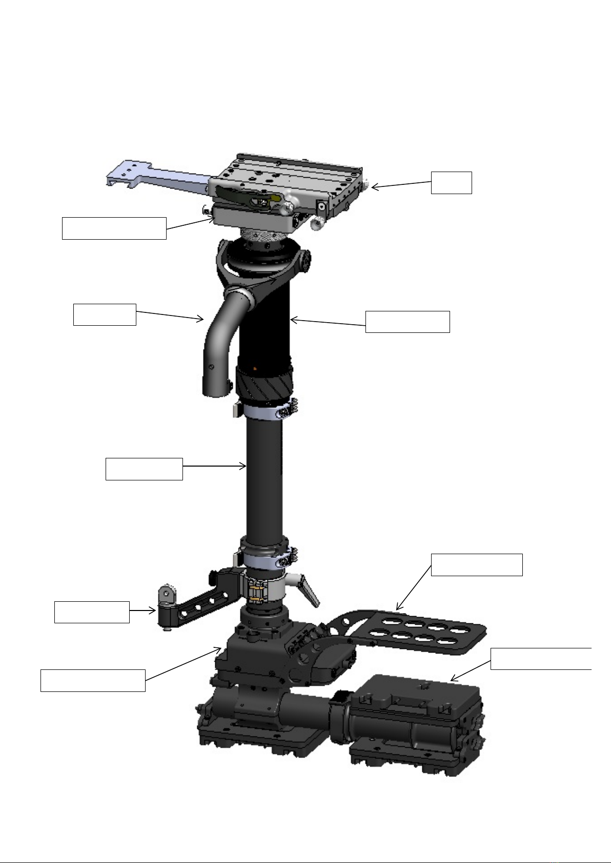
GPI PRO SLED II User manual


FIGURE 1:
DB-III
Upper Junction box
VZ Gimbal Grip
VZ Gimbal
Recorder Mount
Gen 3 Battery Rack
Lower Junction Box
Monitor Arm
Center Post II

FIGURE 2:
This third generation camera-mounting platform offers the following:
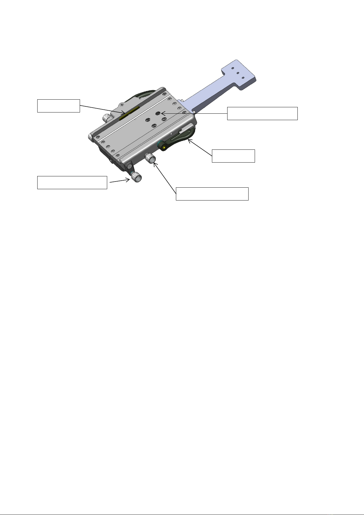
“Cross Roller Bearings” which, by their line contact, as opposed to the point contact of ball
bearings, and their increased length of engagement, multiply the stiffness of the D-Box III, and
allow smooth easy movement fore/aft and side/side.
Access to each of the four mounting screws at once, without the need to adjust the fore/aft or
side/side controls.
A “drop in/out” feature and an independent safety mechanism, so that in the event of a failure in
the locking mechanism, the camera is still secure when the safety lever is in place.
Tool-less rough adjustment of the camera, via the clamp lever located on the right side.
Quick change from hi to lo-mode.
Side/side and fore/aft controls on both the right and left side, for easy access regardless of the
mode you are operating in; high or low, or the side from which you operate; left or right.
Fine thread lead screws and captured lead nuts enable the operator to make small, accurate
adjustments.
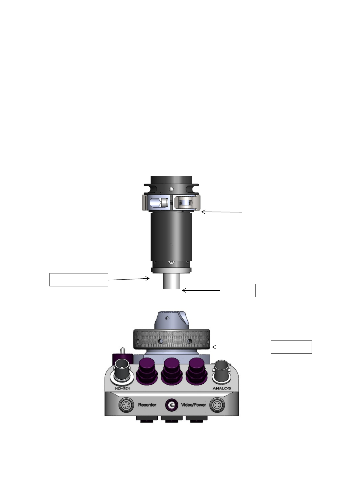
Once the camera has been placed in the Donkey Box, lock the safety lever in place. Then,
ensuring that the clamp lever is in the up and locked position, tighten the locking screw, if this
screw is over-tightened the rough adjustment via the clamp lever will be defeated. For rough
adjustments to the camera’s fore/aft position first turn the clamp lever down (clockwise) then
push or pull to slide the camera into the desired position. Return the clamp lever to it’s locked
position and then use the controls on either side of the Donkey Box for final adjustments, fore
and aft and side to side.
Safety Lever
Fore/Aft Control Knob
Locking Screw

FIGURE 3: ()
Lubrication: Apply lubrication to the locking screw, and the bearings as dictated by shooting
conditions.
Cleaning: Wipe down the visible areas with a light solvent.
Tightening: Do not over-tighten the locking screw, this will defeat the function of the clamp
lever. Set-screws and bearing rails are locked to preset torques at the factory. In the case of any
type of field repair pay close attention to how these screws are put back into place, the preset for
the bearing rails is 17 lbf-in, while the preset for the set screws is 2.2 ozf-in.
Clamp Lever
8-32 Mounting Screws
Side/Side Control Knob
Clamp Block
Fore/Aft Control Knob

Tension Adjustments: In order to adjust the tension or resistance in the knobs it is necessary to
use the D-Box III tool.
For
side/side adjustments it is necessary to first remove the side/side knob on the left side of the D-
Box. The knob is held in place by a set-screw, which is accessible through a hole in the
underside of the D-Box. It will be necessary to remove this set screw using an allen tool. Once
the knob has been removed slide the square-lug end of the tool over the shaft and tighten the
locking nut, while checking the side/side control for the desired tension/resistance.
For fore/aft adjustments use the wrench end of the D-Box III tool to access the locking nut. The
locking nut is located on the underside of the D-Box towards the fore/aft controls. Tighten the
locking nut while checking the fore/aft controls for the desired tension/resistance.

THIRD GENERATION: UPPER JUNCTION BOX
Overall, the upper junction box delivers power to the camera, the focus system and the video tap via your
cables. It is attached directly under the Donkey Box.
BNC Connector
Analog
Provides 12/24vdc
to camera
Provides 12vdc and
video signal
BNC Connector
HD
Figure 1: UPPER JUNCTION BOX (front view)
Provides 12vdc for use with
Arri III High Speed Camera
Provides 12/24vdc
to camera
Provides 12/24vdc
to camera
Provides 12vdc
and video signal
Figure 2: UPPER JUNCTION BOX (rear view)

The PRO™ Gimbal’s design and construction guarantee a precise intersection of all three axes,
while the correct application of bearings provides a smooth, deflection-free pan, roll and tilt. A
locking mechanism achieves concentric clamping about the post, ensuring that all axes converge
at post center. The PRO™ Gimbal is compatible with all 1.5 inch center posts.
For various shot requirements, the gimbal can be moved easily up and down the post by
loosening the clamp screw, sliding to desired position and re-tightening. Once in place fine
adjustments may be made by turning the vernier ring located just below the grip. Approximate
range of fine adjustments is ½an inch in both directions.
FIGURE 6:
-DO NOT OVER TIGHTEN ANYTHING ON THE GIMBAL
I) When tilting the camera, the PRO™ Gimbal is designed to distribute the load of the
camera evenly between its two (2) radial side bearings. If you notice that one side of
the Gimbal yoke is tilting unevenly, the Gimbal yoke may be bent and need replacing.
It is unusual for this problem to occur unless the rig has been dropped or hit.
II) If the Gimbal appears to stick when panning, the pan bearing is most likely dirty
(especially if the operator has been working in very dusty conditions).
To clean, take the following steps:
1. Use the gimbal wrench to remove the outer retaining ring, (while the gimbal is clamped
on the post). Slide outer housing up the post.
2. Clean out the bearing with a non-residue electrical contact cleaner.
3. Re-lubricate with one drop of very light camera oil (ie: Arri Camera Oil)
4. Spin bearing to distribute oil. Re-assemble.
Clamp Lever
Trunnion Cap
Vanier Adjustment
VZ Grip Body
Outer Retaining Ring
Handle

The Generation II system makes use of a quick connect/disconnect assembly at each end of the
post. Inside the post is a coiled cable consisting of (18) conductors all of which are terminated at
each end by a LEMO EGG.3B.856.CLM3 connector. The Generation II Center post does away
with the slotted inner post of the Generation I model. The slot is replaced by a pair of channels
running the length of the innerpost. By doing away with the slot, the Generation II Center post
maintains the rigidity of a fixed post without sacrificing the benefits of an adjustable post.
FIGURE 12:
Outer Post Scales
Outer Post Receiver
Inner Post Receiver
Outer Post
Inner post
Monitor Arm Spacer
Clamp Lever

Located at the top center of the Lower Junction Box is a large 18-pin Lemo jack which provides
the electrical connection point for the Center post Assembly. The Center post Assembly
is attached to the Lower Junction Box as follows:
1. Insert the center post Lemo plug into the Lower J-Box Lemo jack.
2. Attach the post by threading the Locking Ring onto the Post Receiver.
The Generation II Center post utilizes a clamp lever system identical to that of the VZ Gimbal
and Gen III Battery hanger to lock the post at a specific length. To adjust the Center post length,
release the clamp lever and
extend the post to the desired length and close the lever. Maximum post length is 26” end to end.
FIGURE 13:
Clamp Lever
Inner Post Receiver
Locking Ring
Lemo Plug

The Monitor Arm is normally clamped about the spacer, but can also be clamped about the outer
post.
A Kipp handle and a swing arm are used to loosen/tighten the monitor arm clamp about the post.
For quick inversion of the monitor, loosen the thumb screw, twist the monitor arm 180 degrees
and re-tighten the thumb screw.
Locating pins will indicate when the exact 180 degree position has been reached.
The Monitor Arm is connected to the monitor itself via a screw and washer. This screw should
be tight. To tilt the monitor, do it manually – do not loosen the screw.
The Monitor Arm mounting screw needs to be lubricated regularly.
FIGURE 14:
FIGURE 15:
Use the monitor arm extension to position the monitor out further from the sled. Insert the
extension between the two existing monitor arm components using the 10-32 cap screw.
Kipp Handle
Post Clamp
Monitor Arm
10-32 Spud Screw
Monitor Spud
10-32 Monitor Arm Tensioning Screw
Monitor Arm
Monitor Arm extension
1, 2, 3 and 4” Options
Post Clamp
10-32 Screw

The third generation Lower Junction Box (attached directly above the Battery Rack) has been re-
designed to ensure even greater
It’s purpose is to distribute 12 or 24 volt power from each Battery in the battery rack to
respective destinations throughout the sled, namely to: Camera, Monitor, Video Tap, Video
Transmitter, Wireless Lens Control System, On-Board Recorder and Accessories.
FIGURE 16:
12/24 Switch
Recorder Video/Power
Record/Play Back Switch
Video/Power
Monitor Lemo

THIRD GENERATION: LOWER JUNCTION BOX
REAR VIEW
BNC Connector
HD
BNC Connector
Analog
5 amp Breaker
10 amp Breaker
Lemo 0B305
Regulated 9vdc
Recorder power
Lemo 0B304
12vdc and video
signal
Record/Play back
switch
12/24 Safety
switch
Lemo 1B308
12vdc and video
signal
Lemo 3B.856

12
BATTERY MOUNTING SYSTEM
(Gen III and Gen IV)
The PRO™ Gen III Battery Mounting System consists of a tough, tubular structure. The
Battery System incorporates three removable mounting brackets for batteries and is attached to
the Lower Junction Box. The Battery Rack can also house accessories such as an electronic
level sensor, video recorder and video transmitter.
This battery system can utilize any of the Anton Bauer batteries that will physically fit the
allotted space. Be sure to read the instructions that accompany each battery.
FIGURE 17: Gen III BATTERY RACK (front left view)
FIGURE 18: Gen IV BATTERY RACK (front left view)
ThePRO™ Gen IV Battery mounting system has two fixed battery positions and rear telescoping
section. 12/24 volt power for camera and accessories. This unit only comes with (1) jumper
block.

FIGURE 18:
Battery
Legend:
A - Auxiliary
C - Camera Battery
M - Monitor Battery
Three Batteries:
This is the "standard" configuration of the PRO™ Sled. It should be used with 24-volt camera
systems where a separate monitor battery is desired. In this configuration:
1. The (M) supplies 12 volts to the monitor and all video related accessories.
2. The (C) supplies 12 volts to the three camera jacks on the upper J-box.
3. The (A) is able to:
a) in conjunction with the rear lower battery supply 24 volts to separate pins on the
same three jacks
b) supply 12 volts to the Aux. jack on the upper J-Box.
FIGURE 19:
Two Batteries:
a. These two configurations can be used for 12 or 24-volt camera systems but since there is no
separate battery for the monitor in either case, video noise may be present. In both of these
configurations, the (C/M) serves as a 12-volt supply to the three camera
jacks on the upper J-box, as well as to the monitor and all video accessories. By use of the
12/24-volt switch, the second battery (A) can be placed in series with the
(C/M) to supply 24 volts to the three camera jacks on the upper J-box, separated to supply
12-volts to the Aux. jack on the upper J-Box. The choice between the two configurations is
driven by and dependent upon the balance and inertia requirements of the operator, and the
configuration of the other masses on the sled.
b. In situations where only one battery is required the Auxiliary battery (A) in either of
the Two Battery configurations can be removed. This configuration will leave the
(C/M) to supply 12-volts to the camera, monitor and all video
accessories.

1. Whenever possible, turn off Gyros when not in use to save battery power and to limit heat
buildup in the gyro.
2. The inverter can be powered by 12 or 24 volt block batteries, for either gyro spin-up prior to
use or continual use during a shot.
Gyros can be mounted on the PRO Sled by a variety of methods:
1. The AB (Anton Bauer) Gyro Mount can be used to mount a gyro to any of the Anton Bauer
battery mounts at the bottom of the sled.
2. The Camera Plate Gyro Mount can be used to mount a gyro on the low mode bracket camera
plate.
3. The Post Clamp Gyro Mount can be used to mount a gyro to the Center post
FIGURE 25:
The above mounts allow an operator to utilize a number of different possible gyro
locations and orientations. However, because the desired effect depends upon the shot
requirements and equipment variables, specific configurations are impossible to foresee,
and are therefore left to the discretion of the operator.

Spring tension adjustment is accomplished by inserting the Gimbal wrench (5/32”) through the
guide hole at the end of the cartridge and engaging the lead screw. Clockwise rotation of the
wrench effects an increase in the spring tension, counterclockwise a decrease. This adjustment can
be accomplished:
a. before the spring canister is installed in the arm,
b. after installation but before loading the arm,
c. when the arm is under load.
NOTE: It is only necessary to adjust the tension of one (1) spring canister in each arm section.
To install a spring canister, insert it into the arm bone and engage the trunnions with the trunnion
saddles. Align the bores of the drawbar bearings with the locating holes on the vertical link and
the access holes in the bone, and insert a drawbar retaining screw. (see drawing on page 23) Do
not over tighten this screw. To remove a canister, remove the drawbar retaining screw and slide
the canister out of the bone. (The arm must not be under load during these operations.)
Using white lithium grease, lubricate the two drawbar needle bearings and all canister pin (shafts
and threads). This should be done once a month or more frequently depending on the conditions
under which the arm is used. PRO™ ARM
See Next Illustration


Titan and Atlas Arm
Orientation
Orientation of the socket block adapter assembly is critical in that, the
Arm
should never be mounted in such a way that the weight is applied
parallel
to the axis. This incorrect axis orientation is always present
when
using
back mounted
vests.
While utilizing the Titan or Atlas arms on any kind of vehicle
mount.
NEVER! EVER! Place the arms socket block adapter
assembly in
a
situation where the incorrect orientation is possible
or present. This
could
result in a catastrophic failure. Misuse of this
equipment may lead to
injury
of personnel or damaged
equipment.
See Next Illustration

Incorrect
Correct Left Side Mount Correct Right
This manual suits for next models
2