gm-elektronik.swiss | adm@gm-elektronik.swiss D at a sh e et 1811. 0 01
MICROPHONE CONSOLE VA-FMCT-500
Page 7 | 12
Indicator Colour System condition Status Meaning
red Manual emergency
activated
Steady ON, with ALARM LED ON Pre-recorded evacuation
announcement under way
red Manual emergency
activated
Flashing, with ALARM LED ON Pre-recorded alert
announcement under way
green Idle condition Steady Hands-free service
announcement under way
yellow
Fault condition Flashing Zone in failed condition or
unavailable due to amplifier failure
yellow Fault condition Steady Zone set in a «disabled condition»
green
(key)
All Steady Zone selected
28
UK TSC6000-EN
3.4 Sending out messages selectively to broadcasting zones
The keypad of the TSC6000-EN station can be used to pre-select one or more zones to which to send
out hands-free or pre-recorded messages.
Each zone key has three indicators showing its condition:
3.4.1 Sending out messages selectively hands-free
After activating the emergency with the EMERGENCY key (all the keys turn green to indicate general
pre-selection), press the buttons corresponding to the required zones. These will remain green to
conrm that they have been selected. At this point, press the PTT key and hold it down. The microphone
will be activated and it will be possible to send out the announcement hands-free.
At the end of the announcement, release the PTT key and press EMERGENCY again to exit the emergency
mode.
Indicator Colour System condition Status Meaning
Red Manual emergency
activated
Steady ON, with
ALARM LED ON
Pre-recorded evacuation
announcement under
way
Red Manual emergency
activated
Flashing, with
ALARM LED ON
Pre-recorded alert
announcement
under way
Green Idle condition Steady
Hands-free service
announcement
under way
Yellow Fault condition Flashing
Zone in failed condition
or unavailable due to
amplier failure
Yellow Fault condition Steady Zone set in a “disabled
condition”
Green
(key) All Steady Zone selected
27
UK
TSC6000-EN
The status of the EMERGENCY key indicates the condition of the system:
• OFF = emergency de-activated.
• Flashing = emergency under way, activated by another station or by local commands
by the system.
• Steady ON = manual emergency activated from the station itself.
All the keys are active so as to enable the operator to manage the emergency.
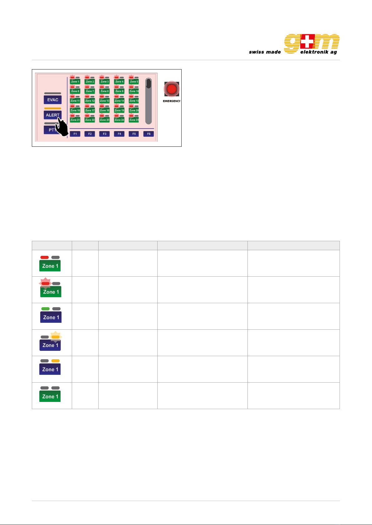
3.3 Sending out pre-recorded evacuation/alert messages
To send out pre-recorded evacuation or alert messages (stored in the memory of the control unit
connected to the TSC6000-EN), after activating the emergency mode (see point 3.2) press ALERT
or EVAC to send out an alert or evacuation message respectively in the broadcasting zones.
The indicators (I) will turn red: if the evacuation message (EVAC) was selected they will remain steady
ON. If the alert message (ALERT) was selected they will be ashing.
Again in this case, if no particular zone was selected beforehand, the selected message will be sent
out by default to all the zones. If you wish to send the message out only in some zones or groups of
zones, consult point 3.4, Sending out messages to selected broadcasting zones (page 28).
To stop pre-recorded messages, hold the RESET/ACK button down until the messages are deactivated
(about 2 seconds).
By pressing the EMERGENCY button again, the messages will be deactivated and the station will
exit the emergency mode. Remember to close the lid again.
Again in this case, if no particular zone was selected beforehand, the selected message will be sent out by default to all the
zones. If you wish to send the message out only in some zones or groups of zones, consult point 2.4, Sending out messa-
ges to selected broadcasting zones (page xx). To stop pre-recorded messages, hold the RESET / ACK button down until the
messages are deactivated (about 2 seconds).
By pressing the EMERGENCY button again, the messages will be deactivated and the station will exit the emergency mode.
Remember to close the lid again.
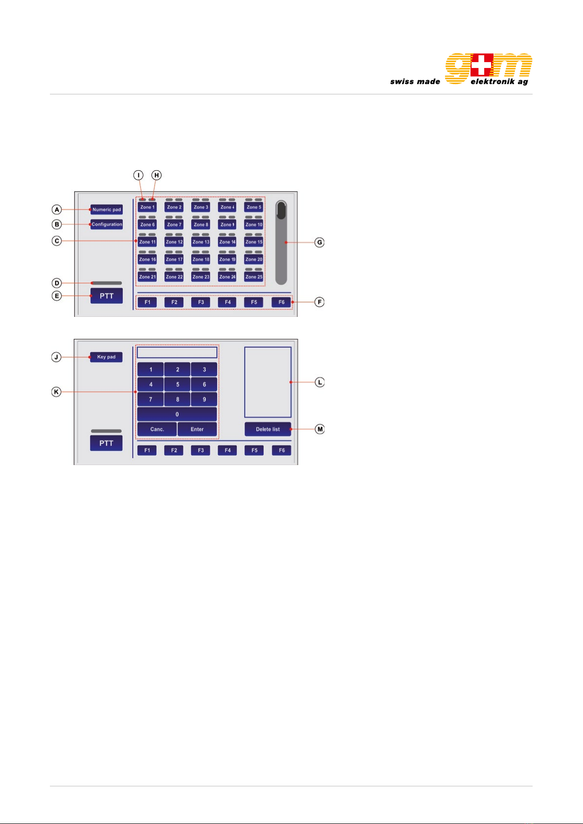
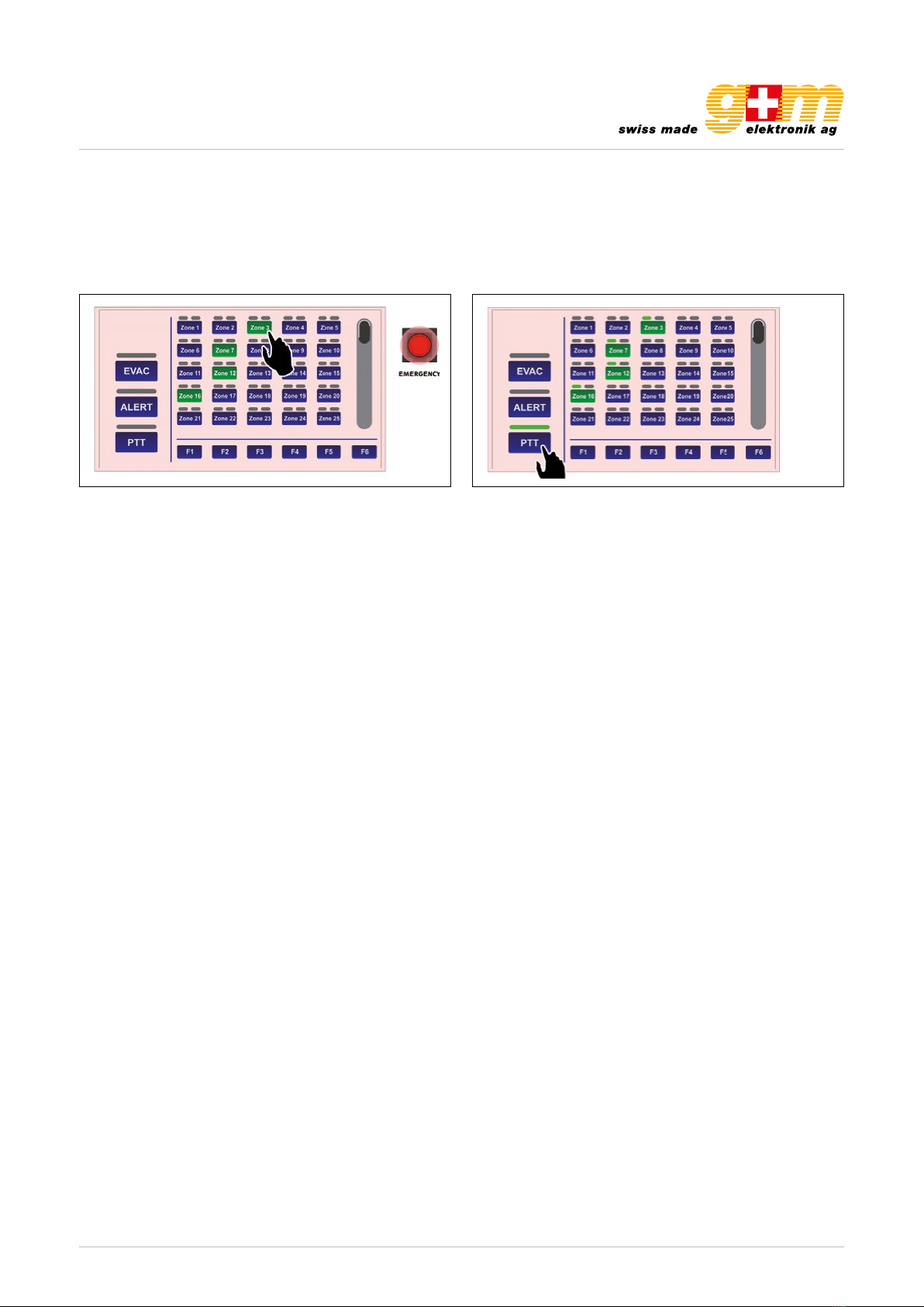
2.4. Sending out messages selectively to broadcasting zones
The keypad of the VA-FMCT-500 station can be used to pre-select one or more zones to which to send out hands-free or
pre-recorded messages. Each zone key has three indicators showing its condition:
28
UK TSC6000-EN
3.4 Sending out messages selectively to broadcasting zones
The keypad of the TSC6000-EN station can be used to pre-select one or more zones to which to send
out hands-free or pre-recorded messages.
Each zone key has three indicators showing its condition:
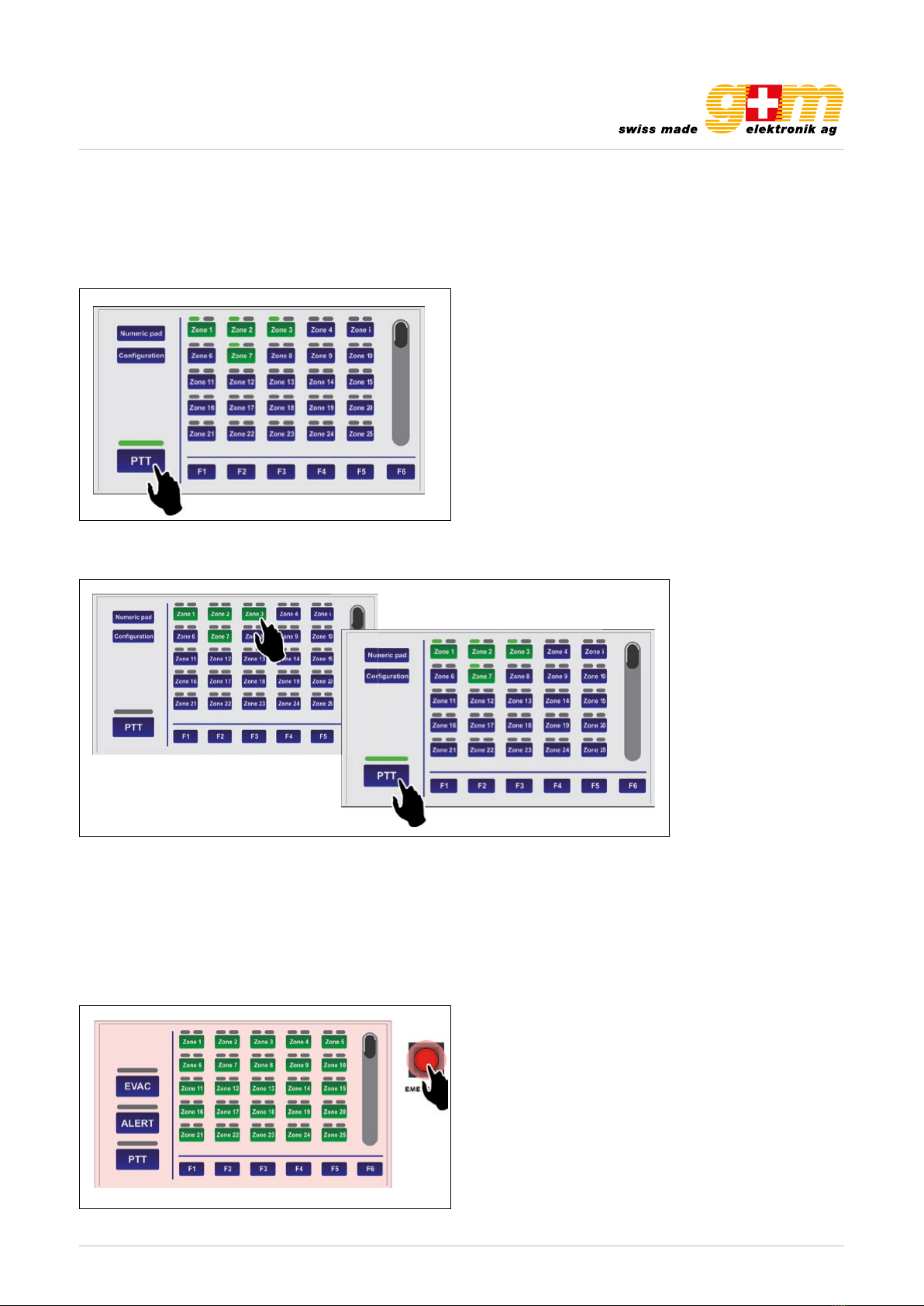
3.4.1 Sending out messages selectively hands-free
After activating the emergency with the EMERGENCY key (all the keys turn green to indicate general
pre-selection), press the buttons corresponding to the required zones. These will remain green to
conrm that they have been selected. At this point, press the PTT key and hold it down. The microphone
will be activated and it will be possible to send out the announcement hands-free.
At the end of the announcement, release the PTT key and press EMERGENCY again to exit the emergency
mode.
Indicator Colour System condition Status Meaning
Red Manual emergency
activated
Steady ON, with
ALARM LED ON
Pre-recorded evacuation
announcement under
way
Red Manual emergency
activated
Flashing, with
ALARM LED ON
Pre-recorded alert
announcement
under way
Green Idle condition Steady
Hands-free service
announcement
under way
Yellow Fault condition Flashing
Zone in failed condition
or unavailable due to
amplier failure
Yellow Fault condition Steady Zone set in a “disabled
condition”
Green
(key) All Steady Zone selected