Nitek TS510 User manual

Rev.080906
NITEK
®
5410 Newport Drive • Rolling Meadows, IL 60008
Phone: (800) 528-4343
Fax: (847) 259-1300
E-mail: info@nitek.net • Web: www.nitek.net
USA Office: De Schans 19-21 2a • 8231 KA Lelysted
Phone: +31(0)320 -23005
Fax: +31(0)320 -23005
E-mail: info@nitek.nl • Web: www.nitek.nl
Europe Office (Netherlands):
Installation and Operation Manual
Model TS510
Active receiver for UTP Transmission
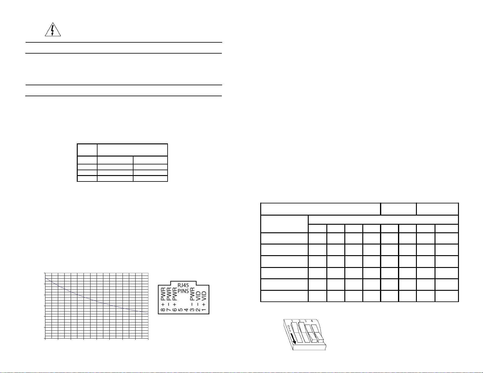
Unmarked Positions are Off Video
Level Gain Video
Peaking
Distance Switch Position
1234567 8
<100-400 ft.
(30-121 m)
400-700 ft.
(121-213 m) ON
700-900 ft.
(213-274 m) ON ON ON
900-1,100 ft.
(274-335 m) ON ON ON
1,100-1,300 ft.
(335-396 m) ON ON ON ON
>1,300 ft.
(396 m) ON ON ON ON ON
1) Check the twisted pair connections for continuity. This is best
donebyshorting thepairof wiresat oneendand use anohmmeter
to check the resistance at the other end. The chart below will give
you the length of your wires for a measured resistance. Use a
multimeter to make sure there is no voltage on the line.
TheTS510Misdesignedtopoweralowwattagestationarycamera.
The unit is designed to work with standard 4 pair network cable. It
will provide power from the receiver unit to the camera end. The
chart belowshowsthe maxiumrecommenededoperationdistance
for cameras on 24AWG wire. For distances greater then the chart
a camera may be powered from a sperate supply of its own. The
TS510Misnotrecommendedfordistancesgreaterthen1,500feet.
Installation
WIRE
GAGE DISTANCE IN FEET
(METERS)
500 (152) 1,000 (304)
22 16 32
24 26 51
26 41 82
Reduce risk of fire or electrical shock do not
expose this product to rain or moisture.
Sample
Switches1 and2 are in“OFF” position
Switches3 and4arein “ON” position
SystemComponents
1 TR510M Active Receiver Unit
1 VB43ATF Transceiver Unit
2) At the camera, connect video to theVB43ATFvia attached
BNC connector.
3) Connect power from the VB34ATF screwless terminals to the
camera using the enclosed twisted pair wired.
4) Plug inCategory3 or better cabling connecting VB43ATF to the
TR510M
5) Using a power supply connect power to the screw terminals of the
TR510Mactive receive. Theunit can bepowered using12 to 24volts
of AC or DC current. There is no polarity to the power connection.
6)ConnectvideofromtheTR510MtothemonitororDVRusingacoax
jump cable.
7) DIP switches are provided so that the unit can be adjusted for
best picture. The following settings are factory recommended for
normal conditions. For added sharpness adjust switches 7 and 8.
For more gain adjust 5 and 6. Switches 1, 2 and 3, 4 must be
operatedinpairs.
0
200
400
600
800
1000
1200
44.5 5 5.5 6 6.5 7 7.5 8
Operating Distance Chart
Camerawattage
Distyance inFeet

Troubleshooting
Video inverted or rolling and unstable.
• Reverse the wires of the twisted pair at either
the transmitter or receiver.
No video out at the receiver.
• Check to make sure that there is video in at
the transmitter.
• Make sure that the pair of wires you are using
is not open or shorted between the transmit
and receive points.
• Check power to the receiver. The receiver must
be powered with the supplied wall pack.
Ghost image at the receiver
• Bridge tap or "T"tap on the twisted pair video
line. Remove tap.
Power Requirements
Power In - Screw Terminals
24-28 VAC 300mA 50/60 Hz
Class 2 SELV
Power Out - RJ45
24-28 VAC 250mA 50/60 Hz
TR510M VB43ATF


