Studiomaster Professional NT Series User manual

1. .......................................................................................................................................................Features
2...........................................................................................................................................Systems Options
3..................................................................................................................................Operating Instructions
4..................................................................................................................................Basic Troubleshooting
5...............................................................................................................................Technical Specifications
6........................................................................................................................................Safety Instructions
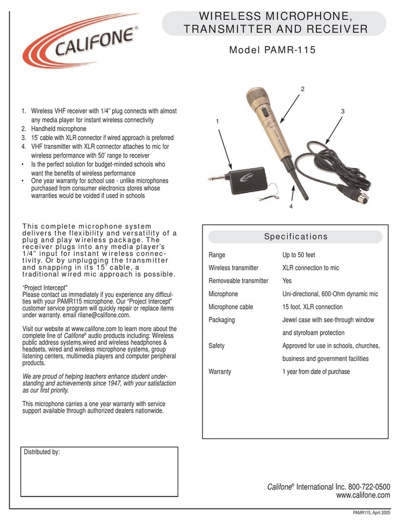
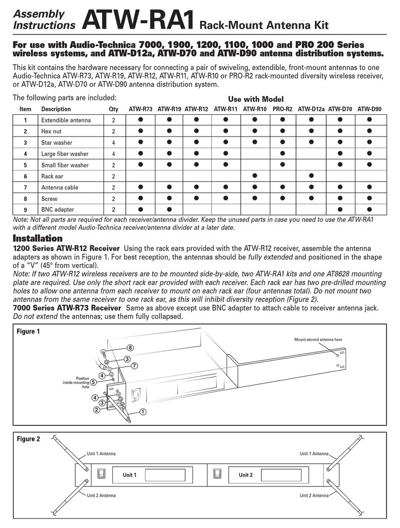
The Studiomaster Professional NT Series is a high quality UHF Wireless technology system engineered for
the most demanding touring environments & installations. This NT Series Wireless systems offers unprecedented
flexibility & versatility. To ensure optimum performance & safety, please follow this instruction manual
carefully. Please retain this manual for future reference. For any complaint, feedback or testimonials please
contact our distributor / dealer.
Professional UHF Wireless Microphone Systems
NT Series

1. Features
2
• High Quality UHF Wireless Microphone System.
• Single Fixed Frequency.
• Backlit Display for Frequency Indication.
• Balanced XLR and Unbalanced 1/4” Jack Output.
• Power On Button & Indication.
• Can be powered by Power Bank (standard USB
connector).
• Rotary Volume Control with Blue LED RF Indication Ring.
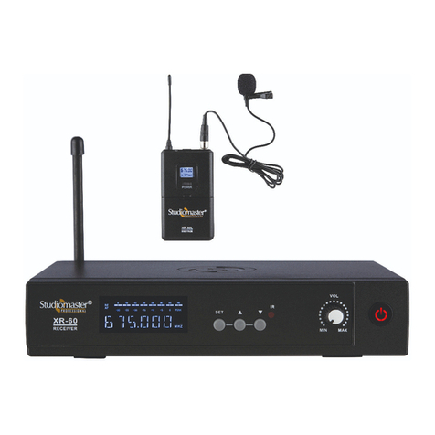
NT-50 RECEIVER
2. System Options
Model:
• NT - 50H (Handheld) • NT - 50L (Lapel)
• NT - 60H (Handheld) • NT - 60L (Lapel)
3. Operating Instructions
3.1 Receiver Description: Front & Rear Panel
Rear Panel NT-50, NT-60
1
RISK OF
ELECTRIC
SHOCK
2 3 4 1
NT-60 RECEIVER
• High Quality UHF Wireless Microphone System.
• 16 Changeable Frequencies.
• Easy Setup via Infrared (IR).
• Backlit Display for Frequency, Channel, RF, AF, Mute
& Transmitter battery level Indication.
• Balanced XLR and Unbalanced 1/4” Jack Output.
• Power On Button & Indication.
• Can be Powered by Power Bank (standard micro
USB connector).
• Rotary Volume Control with Blue LED RF Indication Ring.
NT-50 TRANSMITTER NT-60 TRANSMITTER
• Anti-roll Microphone Grille Design.
• Clear and Crisp Voice Pickup.
• Backlit Display for Frequency Indication.
• Power on/off push button.
• Anti-roll Microphone Grille Design.
• Clear and Crisp Voice Pickup.
• Backlit Display for Frequency Indication, Channel &
Transmitter battery level Indication.
• Selector to Choose Between the 16 Preset Frequency
Channels on-the-fly.
• Power On/Off Push Button.
1. Antenna: The antenna receives signals from the
transmitter. For better signal strength, keep the antenna
fully extended.
2. Power Jack: This standard micro USB connector is
provided for 5V DC input voltage to power up the unit.
3. Balanced Audio Output: This 3-pin XLR male
connector is provided to connect to the input of a mixer/amplifier/powered speaker.
4. Aux Out: This ¼” (6.35mm) unbalanced TRS female connector is provided to connect the Aux out to the input
of a mixer/amplifier/powered speaker.
Front Panel NT-50
1. Power ON/OFF Switch: It is used
to switch the receiver ON/OFF.
2. Power ON LED: This RED LED glows
to indicate the power ON status of the
receiver.
3. Display: The screen is provided to display the fixed channel frequency.
4. LED Ring: This Blue LED ring indicates power on status and availability of the transmitter.
5. Volume Control: It is used to control the audio output signal level from the receiver.
NT 50
RF
1 2 3 54

3
Front Panel NT-60
1. Power ON/OFF Switch: It is used to switch the receiver ON/OFF.
2. IR Sensor: The IR sensor is used for transmitter synchronization.
3. IR Switch: Long press the IR switch to match (synchronize) and set the frequencies between the transmitter
and receiver.
4. Set Switch: Long press the set switch to enter frequency setting menu and single press to switch between
all the 16 preset channels.
5. Display: This LCD screen displays the selected channel, Frequency, RF and AF reception level, Mute and
Battery indication.
NT 60
1 2 5 7643
NT 60
e
a
b
fgh
cd
a. Antenna symbol represents the reception from the transmitter.
b. RF Bargraph shows the transmitter reception level (strength).
c. AF Bargraph shows the audio level from the transmitter.
d. These 3 digits indicate the preset channel number from 001 to 016.
e. These 6 digits indicate the actual operating frequency of the respective/selected channel from 001 to 016.
Please refer to the following table for the channel number & respective operating frequencies.
CH. No. CH. No. CH. No. CH. No.
512.300
512.600
513.000
513.500
514.600
517.000
518.500
520.300
533.300
530.100
524.100
534.600
525.500
535.400
527.200
528.200
Frequency Frequency Frequency Frequency
001 005 009 013
002 006 010 014
003 007 011 015
004 008 012 016
f. It indicates the battery-level of the transmitter.
g. This symbol flashes when the receiver is searching/synchronizing with the receiver via IR (Infrared).
h. This symbol indicates the Mute status of the transmitter. It is visible in following conditions.
• When the transmitter is off.
• When the transmitter battery is dead.
• When there are no batteries inserted into the transmitter.
• Either the transmitter or receiver channel/frequency is different.
6. LED Ring: This Blue LED ring indicates power on status of the transmitter.
7. Volume Control: It is used to control the audio output signal level from the receiver.
Last saved setting (after power ON)
NT 60
001 512.300
Display (OFF)
NT 60
off

4
3.2 Handheld Transmitter Description: NT-50, NT-60
1. Grill: It protects the capsule from damage. It also acts as an effective wind & pop filter.
2. Display: The display on the handheld transmitters of the NT-50 & NT-60 series show different useful operating
parameters as mentioned below.
NT-50: It displays the fixed channel frequency.
NT-60: It displays the selected channel number, frequency and battery indication.
3. Power ON/OFF Switch: Long press to switch the microphone ON or OFF.
4. Battery Cover: Slide down the battery cover to access battery compartment.
5. Battery Compartment: Use 2 x 1.5V AA batteries to power Handheld Microphone.
1
2
3
7
6
15V AAAA
Only for NT-60:
6. IR: This is the IR (Infrared) receiver of the transmitter.
7. Channel Selector Button: Located at the bottom panel of the transmitter, these Up/Down buttons are used to
quickly toggle and choose between the 16 preset frequency channels.
Transmitter ON
512.300
MHZ
FREQUENCY
Transmitter OFF
off
Power ON
888.888
000
CH:
RF-HI RF-LO
CH A CH B
Transmitter ON
512.300
001
CH:
Transmitter OFF
off
3.3 Body Pack Description
1. Antenna: This is the transmission antenna of the body pack transmitter.
2. Power ON/OFF Switch: Long press to switch the microphone ON or OFF.
3. Mic Input: Input socket to connect the supplied lapel microphone.
4 5
4
3
7
5
2
10
9
6
1
Lapel Microphone
8

5
4. Display: The display on the body pack transmitters of the NT-50 & NT-60 series show different useful operating
parameters as mentioned below.
NT-50: It displays the fixed channel frequency.
NT-60: It displays the selected channel number, frequency and battery indication.
5. Battery Cover: Open downward for access to the battery compartment.
6. Battery Compartment: Use 2 x 1.5V AA batteries to power Bodypack unit.
7. Belt Clip: To hang on belt.
8. Microphone (Lapel).
Only for NT-60:
9. IR: This is the IR (Infrared) receiver of the transmitter.
10. Channel Selector Button: Located in the battery compartment of the transmitter, these Up/Down buttons are
used to quickly toggle and choose between the 16 peset frequency channels.
3.4 Frequency response curve for Transmitter
Transmitter ON
512.300
MHZ
FREQUENCY
Transmitter OFF
off
Power ON
888.888
000
CH:
RF-HI RF-LO
CH A CH B
Transmitter ON
512.300
001
CH:
Transmitter OFF
off
NT-50 Transmitter NT-60 Transmitter
Transmitter is Off
Receiver Display
NT 60
001 512.300
1. Check Connections: Confirm if the connections between the receiver and the mixer/amplifier/powered
speakers are correct. Turn down the volume on the mixer/amplifier/powered speakers.
2. As the NT-50 is a single channel fixed frequency wireless microphone system, it auto connects as soon as the
transmitter and receiver are powered up.
1. Check Connections: Confirm if the connections between the receiver and the mixer/amplifier/powered speakers
are correct. Turn down the volume on the mixer/amplifier/powered speakers.
2. Receiver Settings: Switch on the NT-60 receiver, it will display the last selected channel number.
There will be no RF & AF bargraph indication or audio because the transmitter is OFF.
Receiver Display
(When power ON)
NT 60
3.5 Operating the NT-50 Wireless Microphones System
3.6 Operating the NT-60 Wireless Microphones System

6
5. Setting Channel frequency:
3. Transmitter Settings: Switch on the transmitter. The receiver display shows the RF bargraph reception level,
as shown below.
• If the transmitter and receiver frequencies are same.
Receiver Display
4. Testing the Transmitters:
Transmitter Display
512.300
001
CH:
NT 60
001 512.300
Receiver Display Transmitter Display
NT 60
011 527.200
Transmitter: No Audio
Receiver Display
NT 60
001 512.300
Receiver Display
NT 60
Transmitter: Audio
001 512.300
• If the transmitter and receiver frequencies are different.
512.300
001
CH:
• When the user speaks, the audio level will be
indicated by AF reception level (AF).
1) Auto selection:
• Suppose the receiver frequency is at 512.300 (CH 001)
and the transmitter frequency is at 527.200 (CH11)
as shown in figure.
There are two ways to set the transmitter or receiver frequencies, follow the steps given below.
1) Auto Selection 2) Manual Selection
Receiver Display
NT 60
001 512.300
Transmitter Display
527.200
011
CH:
NT-60 Transmitter
NT 60
001 512.300
Before Transmitter
Synchronisation
527.200
011
CH:
512.300
001
CH:
After Transmitter
Synchronisation
Receiver Display
NT 60
001 512.300
Transmitter Display
527.200
016
CH:
• Bring the transmitter and receiver closer and ensure their IR sections are facing each other.
• Long press the IR switch. The transmitter will auto select the frequency of receiver.
• During the synchronization process, the IR symbol flashes on the receiver’s display.
2) Manual selection:
Receiver:
• Suppose the receiver frequency is at 512.300 (CH 001) and the transmitter frequency is at
527.200 (CH 011) and you want to set the receiver frequency same as transmitter i.e. 527.200.
• When the microphone is active, it is indicated
by signal strength (RF) on the receiver.

7
- Make sure you can always see the receiver antenna from the transmitter’s position.
- Keep the distance from the transmitter to the receiver as short as possible.
- Avoid obstructions between the transmitter and receiver.
- Perform a ‘’Walk Test’’ before the performance or presentation. If dead spots are found, change the location
of the receiver. If dead spots remain, mark and avoid them.
Usage Tips
Transmitter:
• Find the channel selector buttons on the transmitter. On the handheld transmitter,
it is located on the bottom panel. On the body pack transmitter it is located inside the
battery compartment.
Step 1: Long press the channel selector buttons (UP/DOWN) to enter the frequency
setting Menu.
Step 2: Single press to switch between 001 to 016 channels.
Step 3: The channel number icon on the transmitter will flash 6 times and the chosen frequency is set.
No Voice; (Signal is normal) • Check whether the level control of the receiver is set enough.
• Check whether the connection between receiver & mixer, mixer & amplifier or
amplifier & speaker are connected. Also check mixer or amplifier volumes are ok.
No Voice; (RF signal is normal
but AF signal is weak)
• Check whether the transmitter battery is fully charged.
• Check whether the level control of the receiver is set enough.
When transmitter is ON, there
is noise or interruption in the
receiving signal.
• Check whether the battery is charged fully.
• Eliminate the RF source of the disturbance nearby which causes interference.
• If the signal is too weak, place the receiver closer to transmitter as far as possible.
4. Basic Troubleshooting
Solution
Problem
No Voice;
(No signal on receiver)
• Check whether power switches of transmitter & receiver are ON.
• Check whether the battery connections are correct & battery polarity is right in
transmitter.
• Make sure that there is no obstruction between the antenna & the transmitter.
• Change the channel number on the NT-60 receiver unit using the Set button.
Step 1: Long press the Set button to enter the frequency select function.
Step 2: Single press the Set button to switch between channels 001 to 016.
Step 3: After selecting the required frequency, the channel number icon
on the receiver will flash 6 times and the chosen frequency is set.
After frequency set
NT 60
011 527.200
Transmitter Display
527.200
011
CH:
Before frequency set
NT 60
001 512.300
Transmitter DisplayReceiver Display Receiver Display
527.200
011
CH:

Rev00/NT Series/16Aug2019
RECEIVER
Operating Frequency Range
Receiving Frequency
Frequency Response
Nominal deviation / peak error
Total harmonic distortion
Dynamic Range
Power Requirement
Current Consumption
S/N Ratio
583-683MHz
NT-50 NT-50
Fixed Variable
40Hz-16KHz
± 15KHz
<1%
> 100dB
DC 5V with standard USB connector
180mA
5. Technical Specifications
TRANSMITTER
Carrier frequency
Frequency stability
Frequency response
Total Harmonic radiation
Dynamic Range
583-683MHz
+0.03%
40Hz-16KHz
<0.02%
>100dB
Use Battery
Current Consumption
Battery Life
2 x 1.5V (AA)
100mA
5-7 hours
6. Safety Instructions
• Keep the wireless receiver in a good location to ensure good signal strength.
• Please keep the product away from direct sunrays & rain.
• Please keep the product away from heavy magnetic or electromagnetic fields, it could affect product performance.
• Please switch off when removing the batteries.
• Please remove the batteries/ power supply when the product is not being used for a long time.
• Do not open any of the components yourself, for repairs please contact an authorised Studiomaster Professional dealer.
• Do not use systems with the same frequency at the same place, please separate them by a considerable distance.
MODEL NAME NT-60
90dB
A1/A2, Giriraj Industrial Estate, Mahakali Caves Road, Andheri (East), Mumbai - 400 093 India.
Tel.: +91-22-42869000 / 001 Whatsapp.: +91-8879028079 E info@audioplus-india.com
W www.audioplus-india.com / www.studiomasterprofessional.com
* Design and specification are subject to change without notice
is a registered trademark of Audioplus in India. © Copyright Audioplus, 2008. All rights reserved.
Any unauthorised reproduction or use of logos, images or design elements is strictly prohibited by law. No part of the
compilation may be reproduced in any manner or translated without written permission.
This manual suits for next models
2
Table of contents
Other Studiomaster Professional Microphone System manuals
Popular Microphone System manuals by other brands
ARCHEAN
ARCHEAN Audio ACCESSIBILITE DCSTS-K015 Installation & user guide
Listen Technologies
Listen Technologies Portable FM 863 MHz brochure
Hollyland
Hollyland LARK M1 user manual
vds
vds VDS6500 installation guide
Maplin
Maplin Prosound N47QR instruction manual

FITNESS AUDIO
FITNESS AUDIO SDR-5716 operating manual
