GPS Insight 3600 User manual

3600 Installation Guide
www.gpsinsight.com |866.GPS.4321 |support@gpsinsight.com
Light/Medium/Heavy Duty •Universal

www.gpsinsight.com |866.GPS.4321 |support@gpsinsight.com
Page 2
Table of Contents
Getting Started
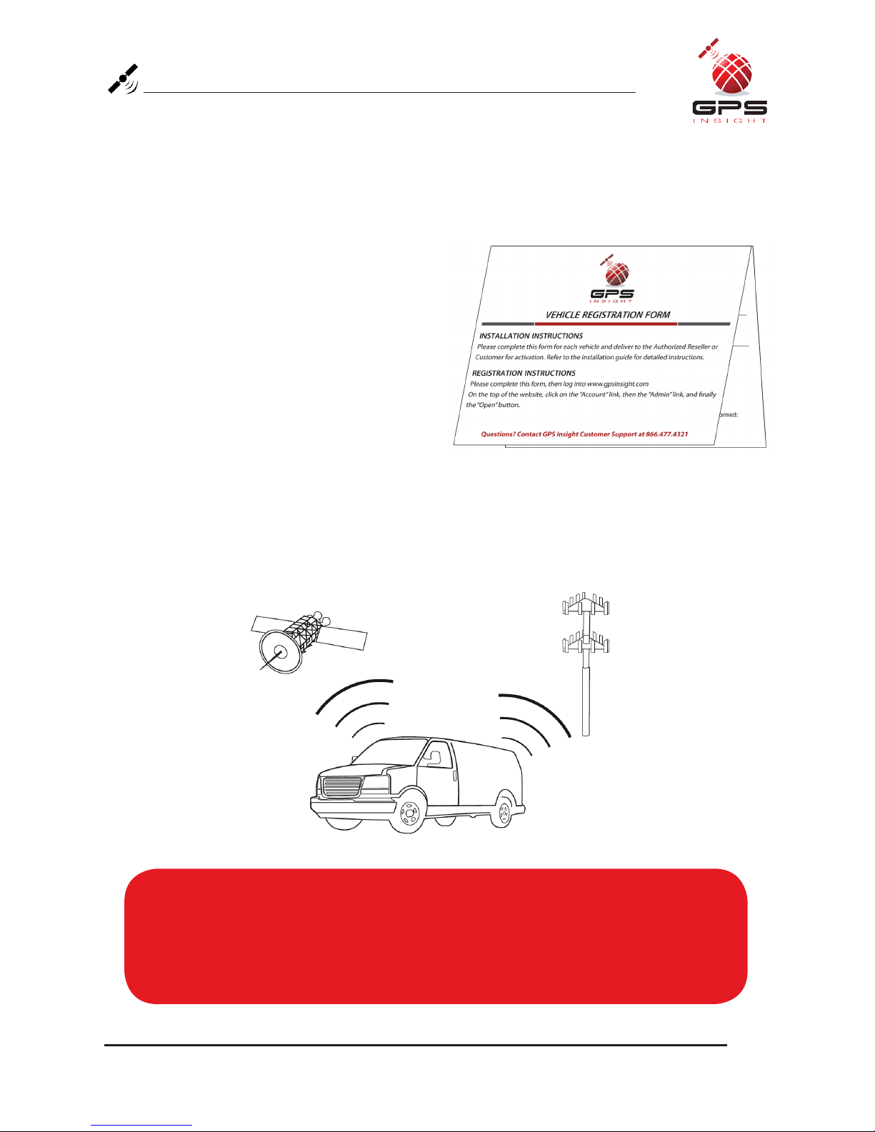
Registration Form...........................................................................................................3
3600 Product Line
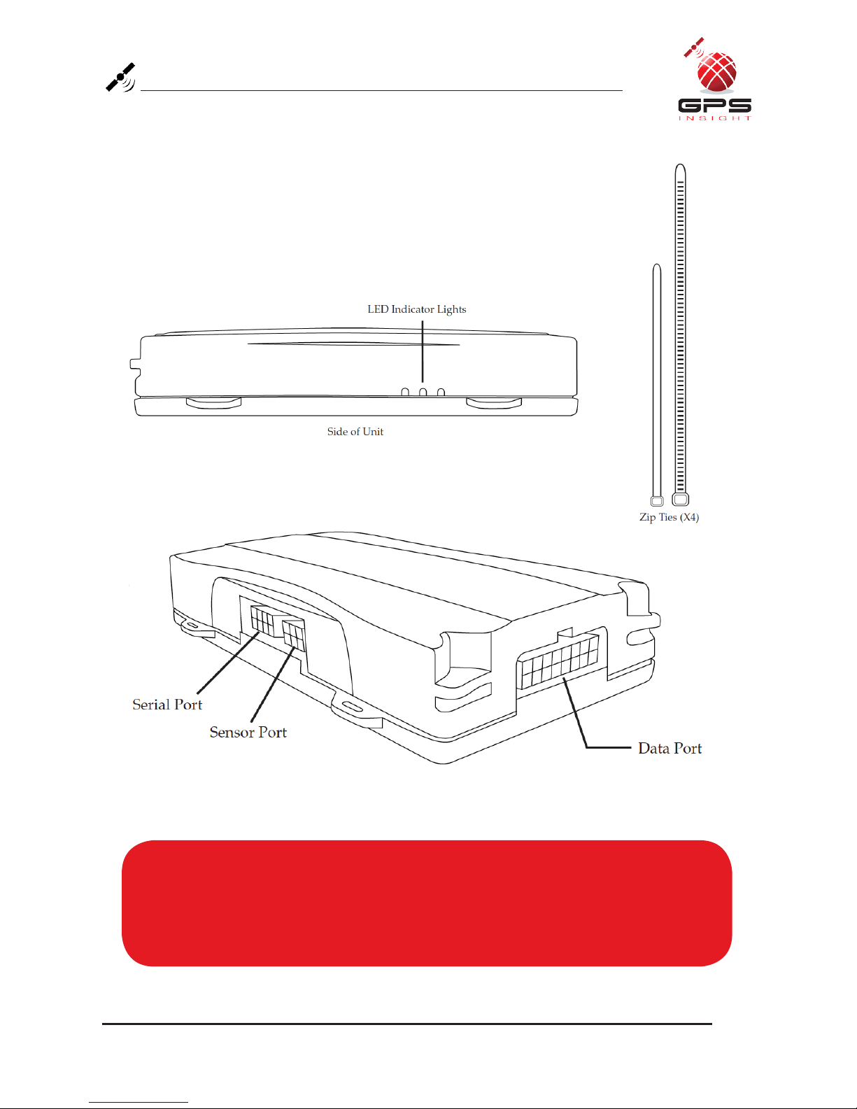
Unit Overview.................................................................................................................4
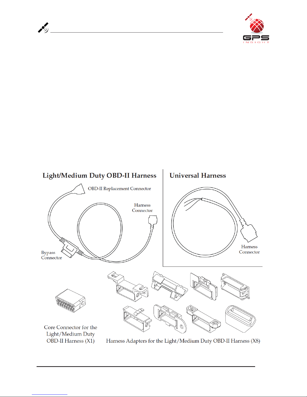
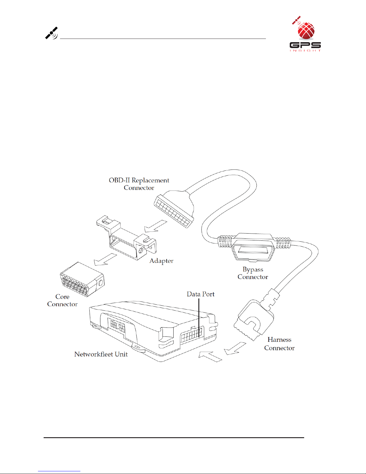
Harness Options for the 3600 Product Line..............................................................5-6
Installation Instructions
Light/Medium Duty OBD-II Harness Installation.....................................................7-9
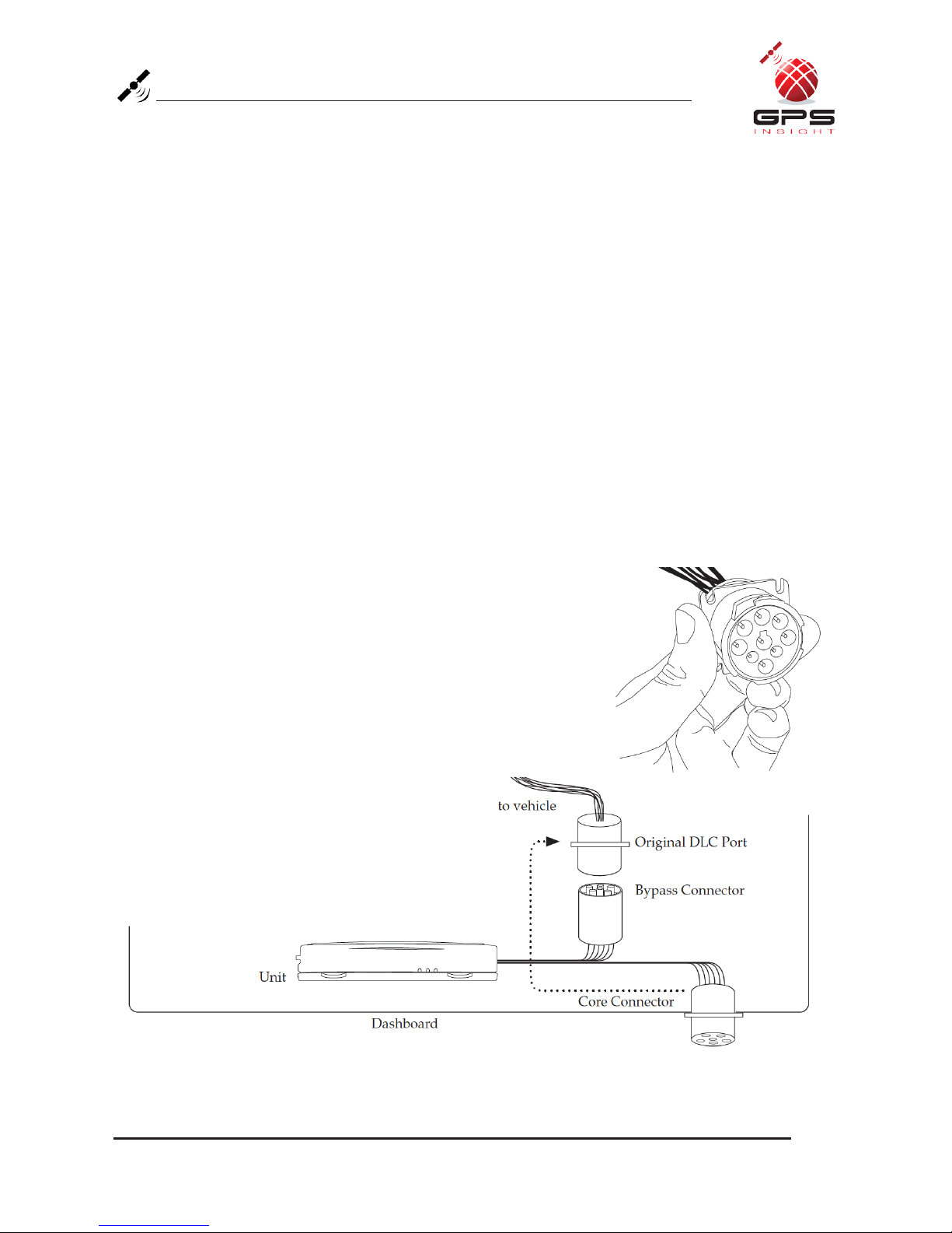
Heavy Duty Harness Installation.................................................................................10
Universal Harness Installation................................................................................11-12
Optional Window-Mount GPS Antenna Installation Instructions.............................13
Verifying Successful Installation...................................................................................14
Creating Tamper Evidence..........................................................................................15
Completing Installation................................................................................................16
Securing the Device......................................................................................................17
Appendix
Troubleshooting Light Indicators................................................................................18
Frequently Asked Questions........................................................................................19
Contact Information.......................................................................................Back Cover

www.gpsinsight.com |866.GPS.4321 |support@gpsinsight.com
Page 3
Registration Form
Fill out the enclosed registration form before completing installation.
Record the following information:
• Vehicle Identification Number (VIN)
• License Plate
• Year
• Make
• Model
• Unit’s Serial Number (10 digits)
1300915003
Installation Tip:
Metal walls and tall buildings may interfere with the reception from GPS satellites and
the cellular network. Perform installation when the vehicle is in clear view of the sky.
Conduct final installation verification after the vehicle has been running outside for
10–15 minutes.

www.gpsinsight.com |866.GPS.4321 |support@gpsinsight.com
Page 4
3600 Product Line Unit Overview
Note:
All 3600 units are shipped with a knock-out panel covering the sensor/serial ports.
In order to access those ports, you must use an X-ACTO knife to slice off 2 of
the 3 tabs in order to remove the knock-out panel.

www.gpsinsight.com |866.GPS.4321 |support@gpsinsight.com
Page 5
Harness Options for the 3600 Product Line
Prior to installation, you must select and order the appropriate harness for
your vehicle type. Please refer to the list below to verify harness compatibility for
each of the 3600 series devices:
3600 (Diagnostic Capable Hardware)
•Light/MediumDutyOBD-IIHarness
•HeavyDutyHarnesses
(6-pin, 9-pin, or 9-pin “D”)
3600 (Non-Diagnostic Hardware)
•UniversalHarness
•Light/MediumDutyOBD-IIHarness
•HeavyDutyHarnesses
(6-pin, 9-pin, or 9-pin “D”)

www.gpsinsight.com |866.GPS.4321 |support@gpsinsight.com
Page 6
Harness Options for the 3600 Product Line
There are 3 different harness options for Heavy Duty vehicle installations:
6-pin Harness, 9-pin Harness, and 9-pin “D” Harness.

www.gpsinsight.com |866.GPS.4321 |support@gpsinsight.com
Page 7
Light/Medium Duty OBD-II Harness Installation
Select an Adapter that most resembles the shape of the OBD-II port of the
vehicle. Use these guidelines to match an adapter to the vehicle it is most
likely to fit (each adapter is stamped with a number).
Ford, GM (1), (6), or (8)
Honda, Lexus, Toyota, Chrysler (2)
Toyota*, Chrysler* (2a)
GM, Saturn (3)
Mercedes, BMW (4)
Porsche, Audi, Volkswagen (5)
Volvo (6)
Saab (7)
* For certain Toyota and
Chrysler vehicles, you may
need to adjust the #2 adapter
by removing the clips on the
top and bottom of the adapter.
To the right is an example of
the adjusted adapter labeled
(2a).

www.gpsinsight.com |866.GPS.4321 |support@gpsinsight.com
Page 8
Light/Medium Duty OBD-II Harness Installation
Core Connector Assembly
1. Snap the selected plastic adapter to the back of the Core Connector.
2. Attach the Core Connector to the OBD-II Replacement Connector.
Data Port Connection
1. Connect the Harness Connector to the Data Port.

www.gpsinsight.com |866.GPS.4321 |support@gpsinsight.com
Page 9
Light/Medium Duty OBD-II Harness Installation
Connecting to the OBD-II Port
1. With the vehicle’s engine OFF, remove the vehicle’s OBD-II port.
•TheOBD-IIConnectormaybehiddenbehindahushpanel.
•Toremovetheconnector,youmayneedtoremovescrewsordepresstheclips.
2. Connect the Bypass Connector to the vehicle’s OBD-II port that was
previously removed.
3. Attach the Core Connector to the position where the original
OBD-II connector was installed. Secure it with the screws or
clips removed from the OBD-II Connector’s original
position (if applicable).

www.gpsinsight.com |866.GPS.4321 |support@gpsinsight.com
Page 10
Heavy Duty Harness Installation
Connecting to the Diagnostic Link Connector (DLC) Port
1. With the vehicle’s engine OFF, unscrew the DLC port from its position under the
dashboard*. In most cases, the DLC port is located under the dashboard on the left side
of the steering wheel, facing toward the floorboard.
2. Plug the Bypass Connector of the harness into the DLC port that was previously
removed from the vehicle in step 1. For the 9-pin connector, turn the rotating cap
clockwise to lock into place.
3. Mount the Core Connector of the harness into the place in which the DLC port
originally resided.
*Note: DLC Port Connector may also be located near or behind the driver seat.

www.gpsinsight.com |866.GPS.4321 |support@gpsinsight.com
Page 11
Universal Harness Installation
Connecting to Ground and Power
Black Wire - Ground
• With the vehicle’s engine OFF, attach the Black Wire directly to a chassis
ground point or to a ground line (chassis ground) by splicing directly to a
ground lead or by using a wire tap (recommended).
Red Wire - Continuous Power
• With the vehicle’s engine OFF, use the voltmeter to locate a 12-volt BATTERY
lead and attach the Red Wire by splicing directly to the lead or by using a wire
tap (recommended). If attaching to a fused lead or using an in line fuse (not
necessary), verify that it is at least 5 amps.
• Be careful not to confuse a “Retained Accessory Power (RAP)” line with a true
Continuous Power line (12 volt, always ON line).
• To determine a true Continuous Power source:
1. Ensure the Driver Door is OPEN
2. Select a wire
3. With vehicle’s engine OFF, use a voltmeter to measure the DC voltage on the
wire. It should show 12 VDC or higher
Note:
Please ensure that the Driver Door is OPEN during the ENTIRE installation process.

www.gpsinsight.com |866.GPS.4321 |support@gpsinsight.com
Page 12
Universal Harness Installation
Blue Wire - Switched Power
• With the vehicle’s engine OFF, use the voltmeter to locate an IGNITION line with
switched power and attach the Blue Wire to the line by splicing directly to the lead
or by using a wire tap (recommended).
• Do NOT use an in line fuse on this line.
• Do NOT use accessory Power.
• To determine a switched power source:
1) Ensure the Driver Door is OPEN
2) Select a wire
3) With engine OFF, use voltmeter to measure the DC voltage on the wire
It should show 0 VDC
4) Start the engine and confirm that the voltage of the same wire is 13.1 VDC or higher
5) Turn the vehicle’s engine OFF and confirm that the voltage of the same wire is 0 VDC
3600 Unit Ground
Yellow Wire
Green Wire
Red Wire
Constant Power (Battery)
Switched Power

www.gpsinsight.com |866.GPS.4321 |support@gpsinsight.com
Page 13
Optional Window-Mount GPS Antenna Installation
To Install
1. Units are shipped with a knock-out panel covering the sensor/serial ports. First,
use an X-ACTO knife to slice off 2 of the 3 tabs in order to remove the knock-out
panel.
2. Use enclosed alcohol preparation pad to clean the inside windshield where the
antenna is to be placed. For proper operation, the antenna should be placed on flat,
clear glass on the driver’s side interior lower corner of the windshield.
Ensure that the antenna does not extend more than 4 ½ inches from the bottom of
the interior windshield and is located outside the area swept by the windshield
wipers.
Do NOT place the antenna in the following areas - Behind stickers or decals
already on the glass, on the shade band of the glass, on a curved area of the glass, on
a moist or damp area of the glass, or on an area that will obstruct the driver’s view
3. Connect the window-mount GPS antenna to the serial port on the side of the unit.
4. Run the cables up the door seam or up through the dashboard.
5. Remove the protective strip from the antenna to expose the adhesive.
6. Carefully affix the antenna to the glass that was prepped in Step 2. Press the
antenna firmly to the glass while being careful not to damage the antenna.
Installation Tip:
Please note that the ideal temperature range to perform the installation is between
70°F to 100°F (21°C to 38°C) with a minimum suggested application temperature
of 60°F (15°C).

www.gpsinsight.com |866.GPS.4321 |support@gpsinsight.com
Page 14
Verifying Successful Installation
1. Start the vehicle’s engine. All lights (Red, Yellow, and Green) on the device should
turn on solid for 15 seconds and then begin blinking rapidly (twice a second).
2. The device is operating normally when the rapid blinking ceases and the Green
and Yellow lights begin to blink in a slow pattern (ON for 5 seconds and OFF for
1 second). The Red light pattern will continue to vary and should not be used to
verify installation.
3. The vehicle must be idled or driven for at least 15 minutes to reach normal
operating mode and ensure activation is complete.

www.gpsinsight.com |866.GPS.4321 |support@gpsinsight.com
Page 15
Creating Tamper Evidence
Once the vehicle harness is plugged in, slide the zip ties through the two slots provided
on the harness connector. Once the zip ties are in place, tighten and remove the excess
plastic. If possible, position the zip ties so that the “DO NOT REMOVE” message is
showing.

www.gpsinsight.com |866.GPS.4321 |support@gpsinsight.com
Page 16
Completing Installation
Before securing the device under the dashboard, make sure that you have recorded
the VIN, hardware serial number, and odometer reading on the registration form.
Also verify that you have checked the light indicators.
vehicle registration form
Time of Install______________________________Date __________________________
Serial #
(10 digit number usually located on back of device)
Vehicle Label____________________________________________________________
VIN#
(must be 17 characters)
Odometer______________________________________________________________
(enter exact mileage at the time of installation)
Country________________________________________________________________
License State_____________________License Plate # __________________________
Color____________________________Make __________________________________
Model___________________________ Model Year______________________________
Installed by______________________________________ Date ___________________
(print name)
Have you veried successful installation using the light indicators?
(see installation guide for instructions)
Yes No
Please check only one box to indicate the location where installation was performed:
Installer Site Customer Site

www.gpsinsight.com |866.GPS.4321 |support@gpsinsight.com
Page 17
Securing the Device
Use zip ties to fasten the hardware securely to a stable bracket or wire bundle under the
dash.
IMPORTANT: The device must be installed high in the dashboard area and secured with
the top of the unit facing the sky (the side of the unit with the manufacturer logo). Also
verify that the device is not covered by metal and check that the green LED is blinking in
a slow pattern, which verifies that the unit is getting GPS data (as explained on page 13).
To avoid damage from condensation, ensure that the unit is not at the lowest
point of the installation and secure it away from moving parts.

www.gpsinsight.com |866.GPS.4321 |support@gpsinsight.com
Page 18
Appendix: Troubleshooting Light Indicators
Issue: Red light continues to blink rapidly
Solution: - Verify that the unit is not surrounded by metal.
- Contact Customer Care to confirm network coverage availability and
the SIM is active.
Issue: Yellow light continues to blink rapidly
Solution: - Contact Customer Care to verify engine computer compatibility.
- If incompatible, install a Universal device.
Issue: Green light continues to blink rapidly
Solution: - With the vehicle’s engine OFF, unplug the device for 3 minutes and
check each item below before reconnecting.
- Verify that the unit is not surrounded by metal.
If using the window-mount GPS antenna:
- Disconnect the GPS Antenna wire and check the antenna wire and
connector for damage.
- Reconnect the GPS antenna wire to the serial port.
- Reconnect device, start engine and keep the vehicle running or drive it
for 10-15 minutes.
Issue: Yellow light stays on solid
Solution: - Verify that you are in an area with wireless coverage.
- Wait 15 minutes with the vehicle’s engine on.
- Verify web portal activation has been completed.
Issue: Green light stays on solid
Solution: - Verify that the unit was installed properly. The side of the unit with the
manufacturer logo should be facing the sky.
- Make certain that the unit is not blocked by underground parking
structures, metal, or trees.
If using the window-mount GPS antenna:
- Disconnect the GPS Antenna wire and check the antenna wire and
connector for damage.
- Reconnect the GPS antenna wire to the serial port.
- Reconnect device, start engine and keep the vehicle running or drive it
for 10-15 minutes.

www.gpsinsight.com |866.GPS.4321 |support@gpsinsight.com
Page 19
Frequently Asked Questions
Q: Are the 3600 series harnesses interchangeable between all other GPS Insight product
lines?
A: No.
Q: When installing the 3600 device, are fuses involved or can the device be “wired hot”?
A: We recommend splicing the 3600 harness to fused leads, though the device can be
“wired hot” since there is an internal re-settable fuse. An in line fuse is not necessary,
however if one is used, it should be at least 5 amps.
Q: Can the window-mount GPS antenna be installed in the A-Pillar?
A: No, the antenna is designed so that it will only function properly with a clear view of
the sky which is best achieved by placing it on the glass windshield.
Q: I need to do a unit transfer. Can I re-use the window-mount GPS antenna? How do I
remove it from the glass?
A: Yes, however the adhesive on the antenna is one-time use only and will not function
properly after it is removed.
Re-installation kits are available - contact Customer Care at 866-477-4321 for more
information.
Instructions for Window-Mount GPS Antenna Removal
Because of the strength of the antenna adhesive, use a razor or Goo Gone (a household
solvent) for removal.
1. To remove the antenna with a razor, peel a small section of the antenna off of the glass
and slide the razor between the glass and the antenna.
2. Using a sawing motion, carefully remove the antenna from the glass and discard.

www.gpsinsight.com |866.GPS.4321 |support@gpsinsight.com
GPS Insight offers 24/7/365 Customer Support
Please contact us today if you have any additional questions about this product.
Toll Free: 1.866.477.4321
Email: [email protected]
Web: www.gpsinsight.com
Table of contents
Other GPS Insight GPS manuals