Graco LineDriver ES Series Use and care manual

Operation, Repair, Parts
LineDriver™ES 3A6623C
EN
For the propulsion of line striping and removal equipment. Not approved for use in
explosive atmospheres or hazardous locations. For professional use only.
Models: 25N555, 25N556
10 mph (16 kph) Maximum Operating Speed
Important Safety Instructions
Read all warnings and instructions in this manual and in related LineLazer,
GrindLazer and ThermoLazer manuals before using the equipment. Save
these instructions.
Related Manuals:
710-0138 Delta-Q Battery Charger
3A6720 Hitch Receiver Kit
LineDriver ES
Model Cord Adapter
--- 25N555 North America
25N556
North America
Australia
CEE 7/7
Denmark
Italy
Switzerland
United Kingdom
Use only genuine Graco replacement parts.
The use of non-Graco replacement parts may void warranty.

23A6623C
Contents
Warnings . . . . . . . . . . . . . . . . . . . . . . . . . . . . . . . . . 3
Component Identification . . . . . . . . . . . . . . . . . . . . 5
Operation . . . . . . . . . . . . . . . . . . . . . . . . . . . . . . . . . 6
Setup . . . . . . . . . . . . . . . . . . . . . . . . . . . . . . . . . . 6
Startup . . . . . . . . . . . . . . . . . . . . . . . . . . . . . . . . 7
Trailer Loading & Unloading . . . . . . . . . . . . . . . . 8
Charging the Batteries . . . . . . . . . . . . . . . . . . . . 9
Maintenance . . . . . . . . . . . . . . . . . . . . . . . . . . . . . . 11
Manual Brake Adjustment or Replacement . . . 11
Throttle Linkage Adjustment . . . . . . . . . . . . . . . 12
Hitch Adjustment . . . . . . . . . . . . . . . . . . . . . . . . 13
Accelerator Calibration (Using Kit 25N880) . . . 14
Transaxle Service . . . . . . . . . . . . . . . . . . . . . . . 15
Repair . . . . . . . . . . . . . . . . . . . . . . . . . . . . . . . . . . . 16
Battery Pack Replacement . . . . . . . . . . . . . . . . 16
Battery Disposal . . . . . . . . . . . . . . . . . . . . . . . . 16
Transaxle Replacement . . . . . . . . . . . . . . . . . . 17
Traction Motor Replacement . . . . . . . . . . . . . . . 17
Motor Controller Replacement . . . . . . . . . . . . . 17
Troubleshooting - LineDriver . . . . . . . . . . . . . . . . 18
Troubleshooting - Motor Controller . . . . . . . . . . . 19
Parts Drawing . . . . . . . . . . . . . . . . . . . . . . . . . . . . . 23
Parts Drawing . . . . . . . . . . . . . . . . . . . . . . . . . . . . . 24
Parts Drawing - Detail Views . . . . . . . . . . . . . . . . . 25
Parts Drawing . . . . . . . . . . . . . . . . . . . . . . . . . . . . . 26
Parts List . . . . . . . . . . . . . . . . . . . . . . . . . . . . . . . . . 27
Wiring Diagram - Harness 25N661 . . . . . . . . . . . . 29
Wiring Diagram . . . . . . . . . . . . . . . . . . . . . . . . . . . 30
Wiring Diagram - Harness 25E406 . . . . . . . . . . . . 31
Technical Specifications . . . . . . . . . . . . . . . . . . . . 32
CALIFORNIA PROPOSITION 65 . . . . . . . . . . . 32
Graco Standard Warranty . . . . . . . . . . . . . . . . . . . 33
Graco Information . . . . . . . . . . . . . . . . . . . . . . . . . 34

Warnings
3A6623C 3
Warnings
The following warnings are for the setup, use, grounding, maintenance, and repair of this equipment. The exclamation
point symbol alerts you to a general warning and the hazard symbols refer to procedure-specific risks. When these sym-
bols appear in the body of this manual or on warning labels, refer back to these Warnings. Product-specific hazard sym-
bols and warnings not covered in this section may appear throughout the body of this manual where applicable.
GROUNDING
This product must be grounded. In the event of an electrical short circuit, grounding reduces the risk of elec-
tric shock by providing an escape wire for the electric current. This product is equipped with a cord having a
grounding wire with an appropriate grounding plug. The plug must be plugged into an outlet that is properly
installed and grounded in accordance with all local codes and ordinances.
• Improper installation of the grounding plug is able to result in a risk of electric shock.
• When repair or replacement of the cord or plug is required, do not connect the grounding wire to either flat
blade terminal.
• The wire with insulation having an outer surface that is green with or without yellow stripes is the grounding
wire.
• Check with a qualified electrician or serviceman when the grounding instructions are not completely under-
stood, or when in doubt as to whether the product is properly grounded.
• Do not modify the plug provided; if it does not fit the outlet, have the proper outlet installed by a qualified
electrician.
• This product is for use on a nominal 120V or 230V circuit and has a grounding plug similar to the plugs illus-
trated below.
• Only connect the product to an outlet having the same configuration as the plug.
• Do not use an adapter with this product.
TRAFFIC HAZARD
Vehicle strikes may result in serious injury or death.
• Do not operate in traffic.
• Use traffic control.
120V US 230V

Warnings
43A6623C
MOVING VEHICLE HAZARD
Careless and reckless behavior causes accidents. Falling from vehicle, running into people or object, or being
struck by other vehicles may result in serious injury or death.
•
Do not operate unless attached to line striping or line removal equipment.
•
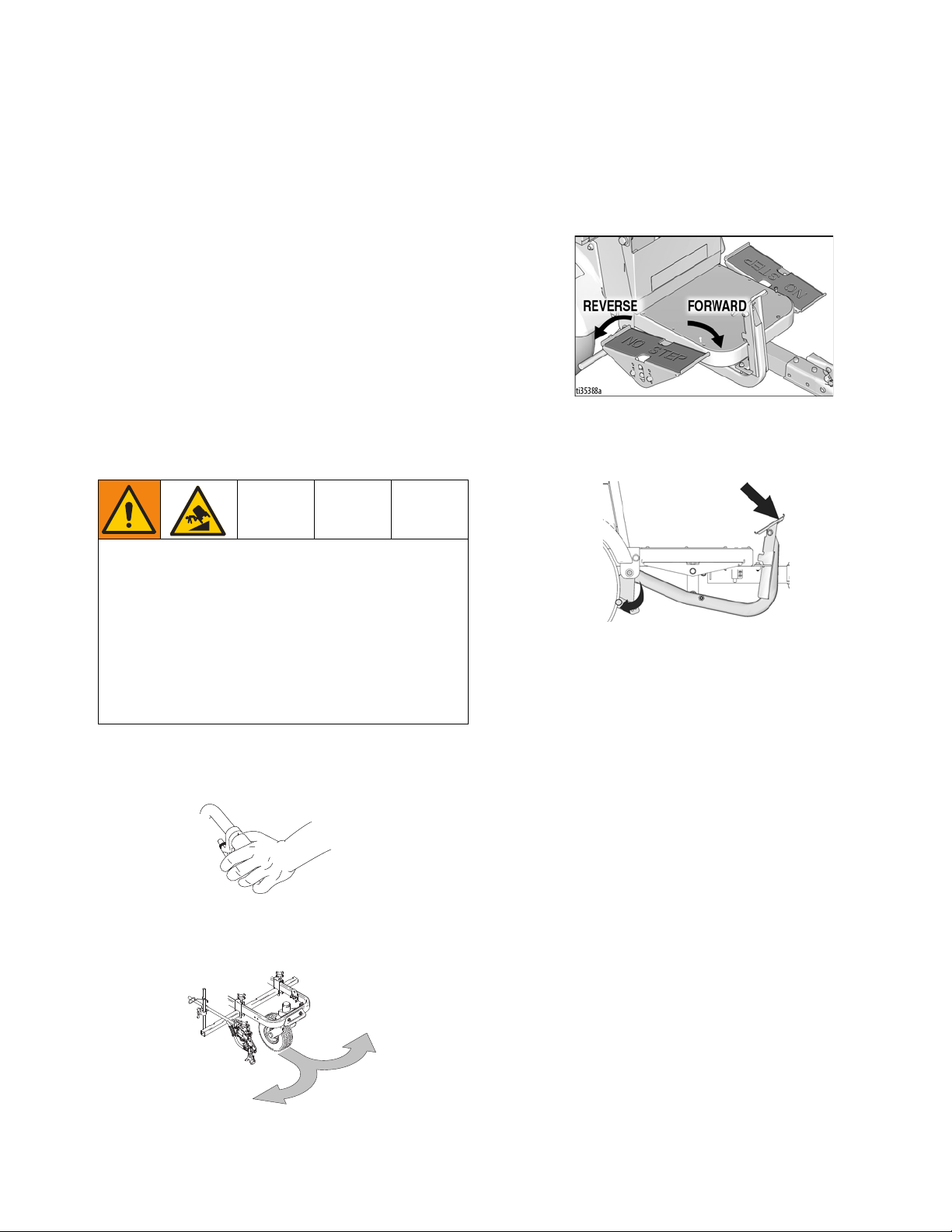
Do not step on forward/reverse pedals.
•
Make turns slowly. Do not make turns greater than 45°.
•
Loss of traction may occur going downhill.
•
Do not operate on slopes greater than 7.5°.
•
Do not carry passengers.
•
Do not tow.
•
Use with line striping or line removal equipment only.
•
Use appropriate traffic control in all traffic areas. Refer to manual on Uniform Traffic Control Devices (MUTCD), U.S.
Department of Transportation, Federal Highway Administration or local highway and transportation regulations.
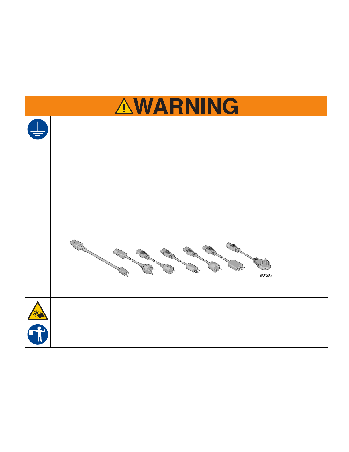
ELECTRIC SHOCK HAZARD
This equipment must be grounded. Improper grounding, setup, or usage of the system can cause electric
shock.
• Turn off and disconnect power cord before servicing equipment.
• Connect only to grounded electrical outlets.
• Use only 3-wire extension cords.
• Ensure ground prongs are intact on power and extension cords.
• Do not expose to rain. Store indoors.
EQUIPMENT MISUSE HAZARD
Misuse can cause death or serious injury.
• Do not operate the unit when fatigued or under the influence of drugs or alcohol.
• Check equipment daily. Repair or replace worn or damaged parts immediately with genuine manufacturer’s
replacement parts only.
• Do not alter or modify equipment. Alterations or modifications may void agency approvals and create safety
hazards.
• Make sure all equipment is rated and approved for the environment in which you are using it.
• Use equipment only for its intended purpose. Call your distributor for information.
• Keep children and animals away from work area.
• Comply with all applicable safety regulations.
BURN HAZARD
Equipment surfaces and fluid that is heated can become very hot during operation. To avoid severe burns:
• Do not touch hot fluid or equipment.
BATTERY HAZARD
Lead-acid batteries produce explosive gases and contain sulfuric acid that can cause severe burns. To avoid
sparks and injury when handling or working with a lead-acid battery:
• Only use the battery type specified for use with the equipment. See Technical Data.
• Read and follow the battery manufacturer’s warnings.
• Exercise caution when working with metallic tools or conductors to prevent short circuits and sparks.
• Keep all sparks, flames, and cigarettes away from batteries.
• Always wear protective eyewear and protective equipment for face, hands, and body.
• If you have direct contact with battery fluid, flush with water and consult a physician immediately.
• Installation and maintenance must be performed by knowledgeable personnel only.
PERSONAL PROTECTIVE EQUIPMENT
Wear appropriate protective equipment when in the work area to help prevent serious injury, including eye
injury, hearing loss, inhalation of toxic fumes, and burns. Protective equipment includes but is not limited to:
• Protective eyewear, and hearing protection.
• Respirators, protective clothing, and gloves as recommended by the fluid and solvent manufacturer.

Component Identification
3A6623C 5
Component Identification
1 Headlight
2 Direction/Speed Pedals
3 Step Plate
4 Hitch
5 Coupler
6 Safety Pin Location
7 Handle Open
8 Handle Locked
9 Manual Brake
10 Tool Tray
11 Seat Adjustment
12 Operator Seat
13 Serial ID
14 Power Switch
15 Speed Switch
16 ExactMil™Speed Control
17 Voltage Meter
18 12V Aux. Power
19 Light Socket
20 Motor Controller Diagnostic Light
21 Battery Charger
22 Seat Lid
23 Buzzer
24 Seat Cover

Operation
63A6623C
Operation
Setup
1. Install supplied ramp onto pallet.
2. Connect Hitch Receiver to line striping or line
removal equipment - Hitch Receiver Kit 25N787
Manual 3A6720.
3. Install LineDriver coupler to striper or grinder hitch
ball.
4. Latch coupler to locked position (M).
NOTE: If coupler is too tight to latch or is loose after
latching, coupler needs adjustment. Refer to Hitch
Adjustment, page 13.
5. Insert safety pin in latch
6. Adjust seat forward/backward with lever below seat.
7. Adjust height of pedals to desired position by
removing/replacing bolts (Y).
8. Loosen two bolts (C) on topside of pedals. Rotate
pedal to desired position. Tighten bolts.
9. Continue onto Startup, page 7.
ti11087a
ti10936a
M
ti11086a
ti11085a

Operation
3A6623C 7
Startup
1. Check battery charge level. Charge if not fully
charged.
2. Sit on seat to actuate safety switch. Ensure pedals
are not depressed.
3. Disengage Manual Brake on LineDriver and
attached equipment.
4. Turn power switch ON. Buzzer will sound in a few
seconds.
5. Operate control to release attached equipment.
NOTE: Interlocks in the LineDriver control system
remove drive power if the Power Switch is OFF, the
Direction/Speed Pedals are engaged when switching
power ON, or the driver lifts themself off the seat.
NOTE: LineDriver motion is forward and reverse. Turns
are made with the striper or grinder.
6. Push striper or grinder handle bars to begin desired
turn.
7. Move pedals to drive LineDriver, as shown below.
Switching from forward to reverse creates a braking
action.
NOTE: LineDriver stops when both feet are removed
from pedals.
8. Set Manual Brake when not operating LineDriver.
This prevents rolling when on an incline.
Operating on an Incline
• Engage the Manual Brake before turning the Power
Switch to OFF when parking on an incline.
• Turn the Power Switch to ON and allow the machine
to initialize before releasing the Manual Brake when
starting on an incline.
Enable ExactMil™Speed Control
ExactMil ensures a consistent paint thickness by holding
the speed steady.
1. Stop moving. Turn speed control knob all the way
counterclockwise.
2. Set Speed Switch to ExactMil position.
3. Depress foot pedal to go forward. Adjust speed con-
trol knob to desired speed setting.
NOTE: ExactMil speed control is only active when mov-
ing forward. Reverse speed is not impacted. ExactMil
speed control limits the maximum speed that can be
obtained with the pedal.
FREEWHEEL HAZARD
Loss of drive power causes LineDriver to freewheel,
which allows it to roll freely.
• Stay fully seated in the driver’s seat while operat-
ing the LineDriver.
• If loss of drive power occurs while LineDriver is in
motion, use the Manual Brake to bring LineDriver
to a stop.
• Always engage Manual Brake before turning
Power Switch OFF or standing up from seat.
ti10937a
ti10935a
ti11009a

Operation
83A6623C
Disable ExactMil Speed Control
• Return Speed Switch to center position.
Enable ECO Mode
ECO Mode can be compared to half-throttle on a gas
powered unit. It is helpful when greater control is
needed, such as loading and unloading, driving in con-
gested areas, and operating on slopes. It also extends
battery life.
• Set Speed Switch to ECO position.
NOTE: ECO Mode limits forward speed to 4 mph and
reverse speed to 2.6 mph.
Disable ECO Mode
• Return Speed Switch to center position.
12V Auxiliary Ports
• 12V auxiliary power ports are provided to power
accessories.
Trailer Loading & Unloading
1. Always keep LineDriver connected to striper or
grinder.
2. Use a level surface to load and unload. Leave suffi-
cient space behind ramps.
3. Use loading ramps sufficiently long and capable of
handling weight of unit and operator.
4. Adjust striper or grinder handlebar to highest posi-
tion. Slide seat back as far as possible.
5. Use right foot to engage Manual Brake. Use left foot
to control speed. Use ECO Mode to limit speed.
6. Slowly drive straight up/down ramps (do not drive at
an angle).
7. Keep a firm grip on handlebars as the ramp is nego-
tiated.
NOTE: Striper or grinder handlebars swing up/down as
the ramp is engaged/disengaged. Keep legs clear.
NOTE: Check Manual Brake clearance to tire and tire
pressure to ensure they are adjusted properly. Refer to
Manual Brake Adjustment or Replacement, page 11.
NOTICE
12V auxiliary ports must be used to power accessories.
Battery damage can result if other means are used to
power accessories.

Operation
3A6623C 9
Charging the Batteries
The charger may be used any time the LineDriver is not
being used. When the batteries are fully charged, the
charger automatically stops. If the LineDriver is stored
for an extended period, the batteries may self-discharge
enough for the charger to automatically recharge the
batteries. For optimum battery life, always leave the
charger plugged in.
Batteries are fully charged when leaving the factory.
Due to self-discharging of the battery, charge battery
before first use. It takes ~18 hours to charge a fully
depleted battery, and ~8 hours to charge the battery 3/4
full.
NOTE: Battery life depends on the depth of discharge
per cycle. A battery that is discharged to 50% depth will
get over twice as many cycles in its life compared to it
being discharged to 100% depth each cycle.
1. Place unit in dry, well-ventilated area and away from
flammable or combustible materials, including
paints and solvents.
2. Position the driver so the wheels are on a true
grounded surface, not on pavement.
3. Ensure power switch is in OFF position.
4. Plug charging cord into charging port on the unit.
Connect an extension cord, per charger manual, to
the charging cord and plug it into wall power.
Always use an outlet that is properly installed and
grounded in accordance with all local codes and ordi-
nances.
Do not modify the plug provided; if it does not fit the
outlet, have the proper outlet installed by a qualified
electrician.
Power Requirements
• All models use the same battery charger. Refer to
Technical Specifications, page 32, for power
requirements.
Replace and charge battery only in well-ventilated
area and away from flammable or combustible mate-
rials, including paints and solvents. The charger may
become hot while charging. Do not touch. Refer to
Charger Manual for additional information.
NOTICE
Lead acid batteries can self-discharge in as little as 3
months depending on storage temperatures. The hotter
the storage temperature, the faster the self-discharge
occurs. To prevent damage to the battery, it is import-
ant to keep the battery in a charged state.
This equipment must be grounded to reduce the risk
of static sparking and electric shock. An electric
shock or static spark can cause fumes to ignite or
explode. An improper ground can cause electric
shock. A good ground provides an escape wire for
the electric current.

Operation
10 3A6623C
5. The Charging Output Indicator means that the char-
ger output is active.
6. When power is connected, charger will immediately
begin charging.
NOTE: Battery will charge to ~30 volts while charging
and then it will come back down to ~27 volts after fully
charging.
NOTE: The Charge Display may show codes to indicate
different conditions. Refer to charger manual for addi-
tional information.
• ‘F’ codes meaning that an internal fault condition
has caused charging to stop.
• ‘E’ codes meaning that an external error condition
has caused charging to stop.
7. When battery charge indicator is solid green, the
charge is complete.
DISPLAY
CHARGING
OUTPUT
INICATOR
USB PORT
STATE OF
CHARGE
INDICATOR
FAULT
INDICATOR
ti35137a

Maintenance
3A6623C 11
Maintenance
Manual Brake Adjustment or
Replacement
1. Block tires so LineDriver will not move. Release
Manual Brake.
2. Ensure power switch is in OFF position.
3. Inflate tires to operating pressure per tire sidewall.
Remove two bolts securing brake rod.
4. Select a hole pattern that positions the brake rod 1/8
to 1/4 in. from the tire.
5. Install two bolts and secure brake rod. Repeat for
second tire.
NOTE: Brake rods are not interchangeable from side to
side. Model shown in the graphic above is the right side
version.

Maintenance
12 3A6623C
Throttle Linkage Adjustment

Maintenance
3A6623C 13
Hitch Adjustment
A coupler too tight or too loose needs to be adjusted.
Before adjusting, check ball and coupler for wear.
Replace worn components.
Ensure power switch is in OFF position.

Maintenance
14 3A6623C
Accelerator Calibration (Using Kit 25N880)
1. Turn power OFF. Engage Manual Brake.
2. Slowly raise hitch coupler until LineDriver rests on
rear bumper.
3. Remove accelerator from LineDriver.
4. Connect calibration cable per illustration. Use a Dig-
ital Multi-Meter to measure volts DC.
5. Mount accelerator to calibration plate and plate to
pedal. This makes it easier to torque fasteners.
6. Ensure nothing is on the operator’s seat so the
safety system prevents wheel movement. Turn
power ON.
7. Loosen adjustment fastener and set neutral position
voltage to 2.45 ± .05 volts. Use calibration plate to
hold accelerator in this position. Torque adjustment
fastener to 90-100 in-lbs.
8. Rotate accelerator arm back and forth, then return it
to neutral position. Re-adjust voltage if necessary.
Turn power OFF.
9. Install accelerator onto LineDriver. When connect-
ing linkage, adjust tie rod end so no pressure is
needed to align parts. Otherwise the LineDriver will
creep.
10. LineDriver may creep forward or reverse when
turned on. As a precaution, jack unit up and use jack
stands to support it (two under the frame in the rear
and one under the coupler).
11. Connect the LineDriver to a striper or grinder, sit on
the seat and turn on. If wheels do not turn (with no
pressure on speed pedals), calibration is complete.
If they do turn, follow Throttle Linkage Adjust-
ment, page 12.

Maintenance
3A6623C 15
Transaxle Service
Check Oil Level (Annually)
1. Turn power OFF. Engage Manual Brake.
2. Slowly raise hitch coupler until LineDriver rests on
rear bumper.
3. Remove fill plug from transaxle cover.
4. Slowly lower hitch coupler. Oil will begin to flow out
of transaxle when hitch coupler is lowered to 10.5 -
12.5” from the floor. Add or remove oil as needed.
5. Reinstall plug.
Change Oil (recommended every 3 years)
1. Turn power OFF. Engage Manual Brake.
2. Slowly raise hitch coupler until LineDriver rests on
rear bumper.
3. Place pan under transaxle cover. Remove screws
and cover.
NOTE: Sealant may hold cover on. If necessary, pry
cover off.
4. Allow oil to drain completey. Follow local ordinances
and regulations for disposal.
5. Clean cover and housing where sealant is used.
Apply new sealant (recommended is RTV silicone).
6. Reinstall cover with screws.
7. Remove drain plug. Fill with 22 oz. of Mobilfluid™
424.
8. Check oil level per above. Reinstall plug.
9. Check for oil leaks. Fix if necessary.

Repair
16 3A6623C
Repair
Battery Pack Replacement
NOTE: Prior to replacing batteries, use Troubleshoot-
ing - LineDriver, page 18, to determine if the batteries
are the cause of the problem. Also, use a battery load
tester to confirm the batteries need replacement. Always
replace all four batteries.
1. Turn power switch OFF. Turn lights OFF. Discon-
nect 12V accessories.
2. Remove Tool Tray.
3. Remove rear screws of Seat Lid.
4. Pivot Operator Seat forward slowly.
5. Remove battery cables.
6. Remove battery holders. Remove batteries and
recycle according to below.
7. Install new batteries in orientation shown. Install
holders and cables.
8. Reinstall seat and Tool Tray.
9. Charge batteries. See
Charging the Batteries
, page
9.
Battery Disposal
Do not place batteries in the trash. Recycle batteries
according to local regulations.

Repair
3A6623C 17
Transaxle Replacement
1. Turn power OFF.
2. Remove rear screws of Seat Lid. Pivot seat forward
slowly.
3. Disconnect battery cables to motor controller.
4. Jack unit up and use jack stands to support unit (two
jacks at the rear and one jack in the front). Raise
wheels about 2 inches off the floor, leaving enough
room to pull the transaxle out.
5. Remove wheels.
6. Remove motor cover.
7. Disconnect wires attached to motor.
8. Place a support under motor and remove transaxle.
9. Place new transaxle under unit. Lay motor wires on
transaxle.
10. Bolt new transaxle to frame.
11. Connect wires to motor. Take care when attaching
the three large cables to prevent damage to the
plastic terminal block on the motor.
12. Install motor cover.
13. Install wheels.
14. Lower unit to the floor and reconnect the battery
cables.
15. Reinstall Operator Seat.
Traction Motor Replacement
Follow Transaxle Replacement, page 17.
Motor Controller Replacement
1. Turn power OFF.
2. Remove rear screws of Seat Lid. Pivot seat forward
slowly.
3. Disconnect battery cables to motor controller. Tape
over terminals to prevent accidental contact.
4. Remove Seat Cover to expose motor controller.
5. Disconnect wires from motor controller.
6. Remove nuts holding motor controller in place.
7. Install new motor controller.
8. Connect wires to new motor controller. Be sure 35
pin connector latches.
9. Install Seat Cover.
10. Reconnect battery cables. Pivot seat back and rein-
stall rear screws of Seat Lid.
11. LineDriver may creep forward or reverse when
turned on. As a precaution, jack unit up and use jack
stands to support it (two under the frame in the rear
and one under the coupler).
12. Sit on the seat and turn on. If wheels turn with no
pressure on speed pedals, follow the Accelerator
Calibration Procedure, page 14.

Troubleshooting - LineDriver
18 3A6623C
Troubleshooting - LineDriver
PROBLEM CAUSE SOLUTION
Manual Brake does not keep Line-
Driver from moving
Marking Brake needs adjustment Adjust Marking Brake
Tire pressure too low Adjust pressure per tire sidewall
LineDriver creeps in forward or reverse
direction
Throttle linkage too long or too short Adjust throttle linkage
Head light does not turn on Connections Repair connections
LED Replace light
Open 10 amp fuse Address cause of high current Replace
fuse
Switch Replace switch
LineDriver does not move forward or
reverse - Voltage Meter ON
Batteries discharged Charge batteries at least 2 hours
Seat safety switch Sit on seat
Speed pedals engaged while turning
unit on
Disengage pedals then turn unit on
Speed pedals engaged for 15 seconds
with no LineDriver movement
Turn power switch OFF then back ON
to reset motor controller
Motor Controller fault Follow Troubleshooting - Motor Con-
troller instructions, page 19
LineDriver does not move forward or
reverse - Voltage Meter OFF
Batteries discharged Charge batteries at least 2 hours
Power Switch OFF Pull knob up
Open 20 amp fuse Address cause of high current Replace
fuse
Open 300 amp fuse Address cause of high current Replace
fuse
LineDriver only moves slowly Manual Brake engaged Disengage Manual Brake
Batteries discharged Charge batteries at least 2 hours
ExactMil™Speed Control ON Increase speed setting or turn OFF
ECO Mode ON Turn OFF
Motor Controller fault Follow Troubleshooting - Motor Con-
troller instructions, page 19
Battery charger not charging Batteries already charged Charge batteries after voltage drops
below 25.0V
Charger has error or fault code Clear code. See charger manual
Batteries discharge within 6 hours of
usage (even when charged overnight)
Manual Brake engaged Disengage brake while operating
Wheels rubbing Clear material away from wheels
Batteries unable to hold charge Replace all four batteries
Charger has error or fault code Clear code. See charger manual
Hitch coupler too tight to latch or too
loose after latching
LineDriver hitch coupler too loose or
tight on ball
Adjust coupler
Voltmeter flashes ON/OFF Batteries discharged and less than one
hour of runtime left
Charge batteries at least 2 hours
Buzzer sounds about once per second Batteries deeply discharged and sys-
tem about to shut off
Charge batteries at least 2 hours

Troubleshooting - Motor Controller
3A6623C 19
Troubleshooting - Motor Controller
Diagnostics
Diagnostics information can be obtained by observing
the fault codes issued by the Status LEDs. See Table 1
for a summary of LED display formats.
The pair of LEDs built into the controller (one red, one
yellow) produce flash codes displaying all the currently
set faults in a repeating cycle. Each code consists of two
digits. The red LED flashes once to indicate that the first
digit of the code will follow: the yellow LED then flashes
the appropriate number of times for the first digit. The
red LED flashed twice to indicate that the second digit of
the code will follow; the yellow LED flashes the appropri-
ate number of times for the second digit.
Example:
B+ Undervoltage Cutback (code 23) and Stall Detected
(code 73).
The controller’s two LEDs will display this repeating pat-
tern:
The numerical codes used by the yellow LED are listed
in Table 2, page 20, which also lists possible fault
causes and describes the conditions that set and clear
each fault.
NOTE: If there are more than one errors active at one
time, the control will cycle through them and repeat.
Summary of LED Display Formats
The two LEDs have four different display modes, indi-
cating the type of information they are providing.
Table 1
Code Display
23 One red, two yellow, two red, three yellow
73 One red, seven yellow, two red, three yellow
Display Status
Neither LED illumi-
nated
Controller is not powered on, or
Vehicle has dead battery, or
Severe damage
Yellow LED flash-
ing
Controller is operating normally
Yellow and red
LEDs both on solid
Controller is in Flash program mode
Red LED on solid Internal hardware fault detected by the
Supervisor or Primary microprocessor.
Missing or corrupt software. Interrupting
a software download may cause corrup-
tion of the software. Cycle power switch
to clear. Reload software or replace con-
troller if necessary.
Red LED and yel-
low LED flashing
alternately
Controller has detected a fault. 2-digit
code flashed by yellow LED identifies
the specific fault; one or two flashes by
red LED indicate whether first or second
code digit will follow.

Troubleshooting - Motor Controller
20 3A6623C
NOTE: When a fault is encountered, shut off the power switch and turn it back on to see if the fault clears. If
it does not, shut off the power switch and remove the 35-pin connector. Check the connector for corrosion
or damage, clean if necessary, and re-insert connector. If the fault persists, follow the instructions below.
When inspecting a cable, always check for a loose terminal fastener, a loose crimp, corrosion, and connec-
tor or insulation damage. Repair or replace components as needed.
Table 2
CODE DESCRIPTION POSSIBLE CAUSE SET / CLEAR CONDITIONS SOLUTION
12 Controller Overcurrent
1. External short of phase U, V,
or W motor connections.
2. Controller defective.
Set: Phase current exceeded the current
measurement limit.
Clear: Cycle power switch.
1. Inspect motor cables U,V,W. Visually
inspect motor terminal block for exter-
nal short circuit.
2. Measure resistance between U, V, W
cables and frame of motor. If resis-
tance is less than 1 megaohm, replace
motor or controller.
13 Current Sensor Fault
1. Leakage to vehicle frame
from phase U, V, or W (short
in motor stator).
2. Controller defective.
Set: Controller current sensors have
invalid offset reading.
Clear: Cycle power switch.
1. Inspect motor cables U,V,W. Visually
inspect motor terminal block for exter-
nal short circuit.
2. Measure resistance between U, V, W
cables and frame of motor. If resis-
tance is less than 1 megaohm, replace
motor or controller.
14 Precharge Failed
1. External load on battery pack
(B+ connection terminal) that
prevents the controller from
charging.
Set: The precharge failed to charge the
capactior bank.
Clear: Cycle power switch.
1. Inspect all cables and connectors from
batteries to controller.
2. Remove any after market devices that
could draw power during system power
up. Only use designated auxiliary ports
for after market devices.
15 Controller Severe Under-
temp
1. Controller is operating in an
extreme environment.
Set: Heatsink temperature below -40°C.
Clear: Bring heatsink temperature above
-40°C, and cycle power switch.
1. Move the unit to a warmer area.
16 Controller Severe Over-
temp
1. Controller is operating in an
extreme environment.
2. Excessive load on vehicle.
3. Improper mounting of control-
ler.
Set: Heatsink temperature above +95°C.
Clear: Bring heatsink temperature below
+95°C, and cycle power switch.
1. Move the unit to a cooler area.
2. Reduce operating load on vehicle.
3. Inspect controller heatsink mounting
for air gaps and tighten fasteners.
17
Severe B+ Undervoltage
1. Non-controller system drain
on battery.
2. Battery resistance too high.
3. Battery disconnected while
driving.
4. Open B+ fuse or main con-
tractor did not close
Set: Battery pack voltage dropped below
the Severe Undervoltage limit with FET
bridge enabled.
Clear: Bring battery pack voltage above
Severe Undervoltage limit.
1. Inspect all cables and connectors from
batteries to controller.
2. Let battery cool then fully recharge bat-
tery. If error happens again, load test
battery and replace if needed.
3. Inspect 300 amp fuse and replace if
open.
4. Inspect contactor for corroded contacts
and replace if needed.
Severe Power Switch
Undervoltage
1. Non-controller system drain
on battery/power switch circuit
wiring.
2. Power switch disconnected
while driving.
3. Open 20 amp fuse.
Set: Below Brownout Voltage for 2 sec-
onds.
Clear: Bring power switch voltage above
Brownout Voltage.
1. Inspect all power switch cables and
connectors.
2. Inspect 20 amp fuse and replace if
open.
18
Severe B+ Overvoltage
1. Battery resistance too high for
given regen current.
2. Battery disconnected while
regen braking.
Set: Battery pack voltage exceeded the
Severe Overvoltage limit with FET bridge
enabled.
Clear: Bring battery pack voltage below
Severe Overvoltage limit, and then cycle
power switch.
1. Let battery cool then fully recharge bat-
tery. If error happens again, load test
batteries and replace if needed.
2. Inspect all cables and connectors from
batteries to controller.
Severe Power Switch
Overvoltage
1. Incorrect (too high) bat-
tery-voltage applied to power
switch (pin 1).
NOTE: Prevents Main Contactor
closure if power switch is greater
than the Severe Overvoltage limit.
Set: Power switch voltage exceeded
Severe Overvoltage limit.
Clear: Bring power switch voltage below
the Severe Overvoltage limit.
1. Check the voltage of each 6V battery
with a digital volt meter. Inspect power
switch and battery wiring for insulation
damage and proper wiring.
This manual suits for next models
2
Table of contents
Popular Lawn Mower manuals by other brands

Scag Power Equipment
Scag Power Equipment SZL36H-18FR Operator's manual

Scag Power Equipment
Scag Power Equipment SWZ Operator's manual

Craftsman
Craftsman 247.203723 Operator's manual

Craftsman
Craftsman 247.288831 Operator's manual

Cub Cadet
Cub Cadet 1212 Operator's manual

Craftsman
Craftsman EZ3 917.251490 owner's manual