Graham-Patten D/ESAM 8000 User manual

D/ESAM 8000
QuickStart Guide
Revision 1.6
January, 2002

Table of Contents
Introduction ...................................................................................... 1
Overview ................................................................................... 1
System...................................................................................... 2
Manual Conventions..................................................................... 3
Define Virtual Machines ....................................................................... 4
Assign Virtual Machines to Logical Machines ............................................ 5
Assign Logical Machines to Faders (Assign Channels) ................................ 7
Assign Logical Machines to Faders - Examples .................................. 8
Configure Bus Assignment.................................................................. 10
Manual Operation ...................................................................... 10
Editor Control ........................................................................... 10
Monitoring Setup ............................................................................. 12
Monitor External........................................................................ 12
Monitor Matrix .......................................................................... 12
Edit Interface Configuration................................................................ 14
Save / Recall Registers ...................................................................... 15
EQ Settings ..................................................................................... 18
Contact Information .......................................................................... 21

Introduction 1
Introduction
Overview
This guide provides a quick introduction to the operations of your new
D/ESAM 8000 audio mixer. You will be up and running very quickly if
you follow the steps outlined in this guide. Several sections have step-
by-step examples after the general discussion of the operation or
feature.
The following information is covered in this QuickStart Guide:
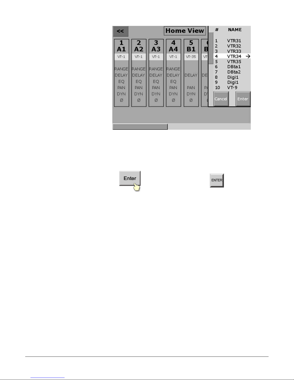
Define Virtual Machines (page 4)
A virtual machine provides the unique ability to
group physical inputs and maintain this grouping
throughout the system via a name and/or number.
Assign Virtual Machines to Logical Machines (page 4)
Edit systems use the traditional Logical Machine
method of identifying sources. The 12 logical
machines (R, A, B, C, etc.) on the D/ESAM 8000 can
be reassigned at any time to a different virtual
machine. In this way, you are not limited by your
edit system’s logical machine sources.
Assign Logical Machines to Faders (page 6)
Once you have defined Virtual Machines and
assigned them to a Logical Machine, this step places
the logical machine on physical faders.
Configure Bus Assignment (page 10)
This section covers how to put a source on the
program and/or preview bus and allows you to re-
route source audio for recording and/or monitoring.
Monitoring Setup (page 12)
The monitoring section of the D/ESAM 8000 is
explained and diagramed. The Monitor Matrix allows
you to re-route monitor inputs to the speaker
outputs and adjust the level to provide a monitor
sub-mix.
Edit Interface Configuration (page 14)
The D/ESAM 8000 is fully controllable by a number
of edit systems and gives you options on the level of
control you would like.

2 Introduction
Save Your Configuration (page 15)
Once you get all this setup, you need to save it to
make it easier to come back to the next time.
EQ Settings (page 18)
Steps and info on using the D/ESAM 8000’s multi-
band EQ.
System
Before we begin, here is an overview of the D/ESAM 8000 system.
The D/ESAM 8000 consists of three units: the CPU controller, the Vadis
audio chassis and the mixer control panel. Your input/output
configuration will vary, since the D/ESAM 8000 offers many choices.
Figure 1 – D/ESAM System

Introduction 3
Manual Conventions
The following conventions are used in this manual:
= a physical button on the control panel.
= a button on the touch sensitive LCD screen.

4 Define Virtual Machines
Define Virtual Machines
Before you can begin using your D/ESAM 8000, you must assign the
physical inputs to a virtual machine. This virtual machine is then used
throughout the D/ESAM 8000 as a way to group the physical inputs
without having to remember which input is what number.
This is done from the controller chassis. This cannot be done from the
D/ESAM 8000 control panel. You will need to now what physical inputs
are associated with which in-house machine (VT-21, Dbeta1, etc.).
Note: Your engineering staff may have already configured this for you.
If so, you can skip this section.
Follow the steps below to configure a virtual machine:
1. If the D/ESAM 8000 program is not already running on the
controller chassis, launch the D/ESAM 8000 application. You will
find a shortcut to this application on the desktop of the CPU
controller chassis.
2. From the top menu choices, click on MAINTENANCE and select
“Virtual Machines” from the pull-down menu.
3. Double–click on the virtual machine name you wish to set up.
4. Click in the box labeled NAME and enter the name as desired.
NOTE: Virtual machine names are limited to 8 characters.
This is to ensure visibility on the Home View screen.
5. Enter the desired tracks for this virtual machine. These tracks
correspond to the physical inputs connected to the back of the
Vadis audio frame. Use the number zero (0) for empty tracks.
6. Press OK to accept your changes and return to the Virtual Machine
List.
Or you may press CANCEL to forget your changes and return to the
Virtual Machine List.
7. If you wish to continue configuring more virtual machines, repeat
steps 3 to 6 above.
8. When you are finished configuring virtual machines, click CLOSE to
close the Virtual Machine List window.

Assign Virtual to Logical 5
Assign Virtual Machines to Logical Machines
Now that you have created your virtual machines, or they have been
created for you, the next step is to assign them to logical machines.
Logical machines are the D/ESAM 8000’s way of keeping track of
groups of physical inputs (virtual machines). The D/ESAM 8000 allows
you to assign 12 logical machines. However, if you have more than 12
virtual machines don’t worry, you can easily re-assign a virtual
machine to a logical machine. You can even save configurations to
recall at any time.
Follow the steps below to assign a virtual machine to a logical
machine:
1. Press the button in the Edit Interface/Config section of the
control panel.
A prompt appears on the LCD screen instructing you to “Press a
Logical Machine button.”
2. Press the desired button in the Rate/Trans section of the control
panel corresponding to the logical machine you wish to assign.
Example:
3. An overlay appears on the LCD screen listing all of the virtual
machines. Use the knob to the right of the arrow on the LCD
screen to scroll the list up or down and select the desired virtual
machine.

6 Assign Virtual to Logical
Figure 2 - Assign Machine LCD Menu
If you wish to assign other virtual machines to logical machines,
repeat steps 2-3 above
4. Press on the LCD screen or press on the control
panel to save your choice(s).

Assign Logical to Faders 7
Assign Logical Machines to Faders (Assign Channels)
In order to actually hear a logical machine, you must assign it to a
fader or group of faders. On the D/ESAM 8000, you have complete
flexibility to bring each channel of your source to an individual fader,
group them all on a single fader or assign stereo pairs to a single
fader. It’s up to you, and you can change this configuration at any
time.
Follow the steps below to assign a logical machine to faders:
1. Press the button in the Edit Interface/Config section of the
control panel.
A prompt appears on the LCD screen instructing you to “Press a
Logical Machine button.”
2. Press the desired logical machine button in the Rate/Trans section
of the control panel.
Or you can press the or button on the control panel
to assign the From or To source.
3. Press the desired fader select button(s) on the control panel to
which you wish to assign this logical machine or From/To source.
These buttons are located above the faders.
Note: If only one fader select button is selected, all tracks
of the logical machine will be grouped on a single
fader. This can be very useful, but if it is not what you
wanted to do, simply press UNDO and start over.
4. OPTIONAL: Press the desired track number you wish to use to
start the assignment.
5. Press to save your changes.
Or to cancel the assignment without saving your changes,
press .

8 Assign Logical to Faders - Examples
Assign Logical Machines to Faders - Examples
Stereo Faders Follow the steps below to assign all 8 channels of Logical Machine A to
faders 1-4 using the Stereo Faders assign feature.
1. Press the button in the Edit Interface/Config section.
2. Press the logical machine button in the Rate/Trans section.
3. Press fader select buttons .
4. Press the button.
5. Press to save your stereo fader assignment.
Grouped Faders Follow the steps below to assign all 8 channels of Logical Machine A to
fader 1 using the Grouped Faders assign feature.
1. Press the button in the Edit Interface/Config section.
2. Press the logical machine button in the Rate/Trans section.
3. Press fader select button .
4. Press to save your grouped fader assignment.
Single Channel Follow the steps below to assign only channel 3 of Logical Machine A to
fader 2 using the Single Channel assign feature.
5. Press the button in the Edit Interface/Config section.
6. Press logical machine button in the Rate/Trans section.
7. Press the button in the Menu Selection/DMEM section.
8. Press fader select button .
9. Press to save your single channel assignment.
Auto Channels - From Follow the steps below to assign the From source to faders 1-4 using
the Auto Channels assign feature.

Assign Logical to Faders - Examples 9
1. Press the button in the Edit Interface/Config section.
2. Press the button next to the Rate/Trans section.
3. Press fader select buttons .
4. Press to save your assignment
Auto Channels - To Follow the steps below to assign the To source to faders 5-8 using the
Auto Channels assign feature.
1. Press the button in the Edit Interface/Config section.
2. Press the button next to the Rate/Trans section.
3. Press fader select buttons .
4. Press to save your assignment.

10 Configure Output Bus Assignment
Configure Bus Assignment
The D/ESAM 8000 operates with a familiar video switcher-style
interface whereby sources are placed on Program and/or Preset buses.
When a transition is initiated, either manually with the Trans Start
button on the control panel or via an edit controller, the D/ESAM 8000
will transition from the source on the Program bus to the source on the
Preview bus.
Bus assignment is the way to take channel 2 of your source and have
it go out to channel 1 of the master, for example. The D/ESAM 8000
offers you an easy method for adjusting the output bus assignment of
logical machines.
Manual Operation
In manual operation, you can simply press the desired output bus
button (labeled 1-8 vertically above the faders) and adjust the faders
to the desired level to configure your source.
Follow the steps below to manually configure the output bus
assignment:
1. Press , or both buttons on the control panel to select
which output bus you are configuring.
2. Simply toggle on or off the output bus buttons for the desired
source. These are labeled 1-8 vertically above the faders.
Additionally, you can set the output level by adjusting the faders
for the desired source.
Editor Control
Under editor control, whenever you select the source on the editor, the
default output bus assignment will be selected on the mixer. If you do
not want the default configuration then you must configure the bus
assignment.

Configure Bus Assignment 11
Follow the steps below to configure the output bus assignment for use
with an edit controller:
1. If you want to know the current configuration for a desired source,
select it on the edit controller.
2. Press to enable configuration mode.
3. The D/ESAM 8000 allows you to configure each source uniquely on
the source and preview buses. Most users configure both buses
identically. For your convenience, Both is selected by default, so if
you do not wish to configure both source and preview outputs,
then choose which buses you wish to configure by pressing
, or
4. Press the desired button in the Rate/Trans section of the control
panel corresponding to the logical machine you wish to configure.
Example:
The D/ESAM 8000 places the current configuration for the selected
machine on faders 11-18. If the selected machine is only a 4
channel machine, the faders 15-18 will be used, and so on.
5. Simply toggle on or off the output bus buttons for the desired
source. These are labeled 1-8 vertically above the faders.
6. Press on the LCD screen or press on the control
panel to save your configuration.
Or to cancel Config without saving your changes,
press .

12 Monitoring Setup
Monitoring Setup
The D/ESAM 8000 allows you to have full control over the entire
Preview Bus Matrix. Levels can be adjusted, monitor buses can be
remapped to other monitor buses and all is saved for future use.
There are two modes of monitor operation: monitor external or
monitor matrix.
Monitor External
In monitor external mode, the Monitor Matrix and output level knob
are disabled. Additionally, the matrix is locked in a default routing
with bus 1 to output 1, bus 2 to output 2, etc.
To enable the Monitor External mode of operation do the following:
1. Press the button in the monitor section of the upper control
panel.
Monitor Matrix
When monitor matrix mode is active, faders 11-18 are used to display
the monitor outputs as follows:
Fader 11 = Monitor Output 1
Fader 12 = Monitor Output 2
Fader 13 = Monitor Output 3
Fader 14 = Monitor Output 4
Fader 15 = Monitor Output 5
Fader 16 = Monitor Output 6
Fader 17 = Monitor Output 7
Fader 18 = Monitor Output 8
To set up the Monitor Sub-Mix mode of operation do the following:
1. Press the button in the monitor section of the upper control
panel to enable Monitor Mix mode.
If you want to adjust the individual monitor channel levels,
continue with step 2.
Or to leave monitor levels at their default setting and to make
adjustments to the output bus mapping, skip to step 3.
2. To adjust the monitor output levels, you must first check the state
of the output bus buttons (labeled 1-8 vertically above the fader).

Monitoring Setup 13
There are 3 color states for these lamps:
•Red – output levels can be freely adjusted.
•Green – the output level is locked for that channel.
•Off –the monitor output is turned off.
Once the lamp is red, simply move the fader as you wish.
3. To adjust the routing of the monitor output bus, simply toggle on
or off the desired output bus buttons corresponding to the monitor
channel you wish to control. Remember the color states above:
Red = adjustable, Green = locked, Off = off.
4. To exit Monitor Sub-mix mode and temporarily save your changes,
press . These settings will be here the next time you enter
Monitor Mix mode.
Or to exit Monitor Sub-mix mode without saving your changes,
press .

14 Edit Interface Configuration
Edit Interface Configuration
The D/ESAM 8000 is configured from the factory for either ESAM II or
D/ESAM IV protocol, selected by the edit controller. One button is all
that is required for Editor Control. However, if you would like
individual, breakaway control over sources, previews, transitions and
rates, the D/ESAM 8000 offers that, too.
Follow the step below to enable Editor Control:
1. Press the button in the Edit Interface/Config section of the
control panel.
This button along with the other 4 edit interface breakaway
buttons will illuminate. To disable editor control of the D/ESAM
8000, repeat the step.
Follow the step below to enable or disable editor control over Sources,
Preview Monitoring, Rates and/or Transitions:
1. Press any of the edit interface breakaway buttons in the Edit
Interface/Config section of the control panel:
The corresponding button will illuminate to show it is being
controlled by the editor or dim to show it will not be controlled.

Save / Recall Registers 15
Save / Recall Registers
The D/ESAM 8000 is configured to automatically save your last
configuration. This way, when you have to reboot, it will come right
back to where you left off.
The D/ESAM 8000 also offers you over 8000 registers to save your
own mixer setups. These registers are divided into 2 categories:
configuration and panel memory (D/MEM). The difference is that the
configuration registers save more information than the D/MEM
registers.
The following table lists the data categories that are stored and
recalled to the panel for both D/MEM and configuration registers:
Register
Data Categories1D/MEM
Reg. Config
Reg.
Channel assignments ü ü
Edit interface enables ü
EQ settings ü ü
Dynamics settings ü ü
Fader range ü ü
LCD Background ü
LCD Brightness ü
Link status ü ü
Lock status ü ü
Logical Machine assignments ü
Mix Out mode ü ü
Monitor Levels ü
Monitor Modes ü
Monitor Sub-Mix ü
Panel LED Brightness ü
Preset crosspoints ü ü
Preset faders ü ü
Preview crosspoints ü ü
Program crosspoints ü ü
Program faders ü ü
Source/Preview Configuration ü ü
Transition bus enables ü ü
Transition rates ü ü
1Some features may not be implemented yet.
Table 1 - Register Data Categories

16 Save / Recall Registers
Follow the steps below to save a configuration register:
1. Press the button in the Menu Selection/DMEM section of the
control panel.
2. Press to denote you want this to be a configuration register.
3. Press the desired register number.
4. Press to save your configuration.
Follow the steps below to save a D/MEM register:
1. Press the button in the Menu Selection/DMEM section of the
control panel.
2. Press the desired register number. Remember not to press the
zero button or you will be saving/overwriting a configuration
register.
3. Press to save your DMEM.
Follow the steps below to recall a configuration register:
1. Press the button in the Menu Selection/DMEM section of the
control panel.
2. Press to denote you want this to be a configuration register.
3. Press the desired register number.
4. Press to recall your configuration.

Save / Recall Registers 17
Follow the steps below to recall a D/MEM register:
1. Press the button in the Menu Selection/DMEM section of the
control panel.
2. Press the desired register number. Remember not to press the zero
button or you will be recalling a configuration register.
3. Press recall your DMEM.

18 EQ Settings
EQ Settings
The D/ESAM 8000 offers a fully featured parametric equalizer. You
have control over both low and high bands as well as 4 mid bands.
Since adjustment of the EQ on the D/ESAM 8000 is pre-fader control,
you also can adjust the pre-EQ gain to compensate for any additional
gain that results from applying EQ.
Follow the steps below to adjust the EQ settings:
1. Press the desired fader select button(s) on the control panel to
which you wish to apply EQ. These buttons are located above the
faders.
2. Press on the LCD screen.
The EQ Adjust Menu appears in the right-hand LCD screen.
3. Press on the LCD screen to toggle the EQ feature on.
The selected faders are outlined in yellow to indicate that EQ will
be applied to these faders. This same button is used to turn EQ
off if you want to compare the settings you made with the
original, un-EQ’d source.
4. Select the EQ band you wish to adjust by touching the
button on the LCD screen.
Or you can turn the bottom soft knob to the right of the LCD
screen to select the EQ band.
The following is a list of EQ bands and available controls:
EQ Band
EQ
Setting Low Mid1 Mid2 Mid3 Mid4 High Gain
Gain ü ü ü ü ü ü ü
Frequency ü ü ü ü ü ü
Qü ü ü ü
Table 2 – EQ Settings
Other manuals for D/ESAM 8000
1
Table of contents
Other Graham-Patten Music Mixer manuals