Graham-Patten D/ESAM 820 User manual

D/ESAM 820 User’s Guide Alignment •Error! Main Document Only.-1
Alignment
Fader Alignment
Use the following procedure to align the Control Panel faders such that electrical
fader position matches physical fader position:
1. Ensure that monitor levels for all channels are turned down.
2. Take all faders and physically move them to their uppermost limit (+6
dB position). Leave each fader there.
3. To align faders, press LOCK/UNLK, hold it down and press FADER
SPLIT. Electrical position now matches the physical scale printed on
the panel. This completes the fader alignment process.
Changing Input/Output Levels
The following topics are discussed in this section:
•Analog Input Alignment, Assy. #04-0160-01
•AES Input Module — installation and jumper settings
•Audio Output Module
•Meter Output Adjustments
•Program Output Adjustments
•Monitor Output Adjustments

Error! Main Document Only.-2 •Alignment D/ESAM 820 User’s Guide
Analog Input Alignment, Assy. #04-0160-01
D/ESAM’s Analog Input Module (Assy. #04-0160-01) accepts eight balanced or
unbalanced audio signals. The figure below shows the adjustment locations:
12345678
1 2 3
1 2 3
-5 GND +5 +15
Gain
Trims
Resistor
Networks
ANALOG INPUT MODULE
04-0160-
-15
Input Terminations
(Terminating Resistors)
Analog Input Module (Assy. #04-0160-01)
Each pair of inputs on the module can be set for an operating level of -10dBu to
+14dBU. Operating levels are changed by replacing resistor networks (socketed),
which are available from GPS. Use the table below to select the appropriate resistor
network:
Analog Input Range (Assy. #04-0160-01)
Resistor
Network Adjustment
Range
10K -10dBu – 0dBu *
20K -4dBu – +6dBu
50K +4dBu – +14dBu
Notes:
* 0 dBu equals 0.775V RMS.
Each input can be terminated by installing a terminating resistor (¼ Watt, 1%, 150Ω
or 600Ωstandard values) on the module at locations 2R1 - 5R2.
The Analog Input Module has been factory aligned. Adjustments should not be
required unless reference level or the digital pad has been changed for particular
inputs or components have been replaced.

D/ESAM 820 User’s Guide Alignment •Error! Main Document Only.-3
Use the following procedure to align the module. All other alignments are done at
the system level:
1. Ensure that the meter and Program outputs are calibrated. See the
“Meter Output Adjustments” and “Program Output Adjustments”
sections for details.
2. Apply a reference tone to the inputs to be tested.
3. Select R in the Preview Section on the Control Panel and assign virtual
machine which contains the inputs to be aligned to R. Refer to the
“Machine Assignment” section in Chapter 3 for machine assignment
procedures. The meters should now display the inputs to be aligned.
4. Locate the appropriate GAIN TRIM on the board. Adjust each input’s
gain as required for 0VU (-8PPM) on the Meter Panel.
NOTE The internal tone generator can be used for alignment. In Chapter 5, refer to the
“Alignment - Menu 6.1” section for setting tone generator options.

Error! Main Document Only.-4 •Alignment D/ESAM 820 User’s Guide
AES Input Module
D/ESAM’s AES Input Module (Assy. #04-0164-00) is shown below:
DIGITAL INPUT
04-0164-
GND +5V
1 2 3 4 5 6 7 8 9
1 2 3 4 5 6 7 8 9
123456789
INPUT 7/8INPUT 5/6INPUT 3/4INPUT 1/2
110 250
AES RECEIVERS
1/2 3/4 5/6 7/8
INPUT ERROR
GRAHAM-PATTEN SYSTEMS
GRASS VALLEY, CALIFORNIA
Made In U.S.A.
CONTROL
ADDRESS
BLOCK AUDIO
ADDRESS
BLOCK
SYNC
*
ASYNC
110 250
SYNC
*
ASYNC
110 250
SYNC
*
ASYNC
110 250
SYNC
*
ASYNC
*
*
1J1
1J3
2J1
2J3
3J1
3J3
4J1
4J3
e
AES Input Module (Assy. #04-0164-00)
The Digital AES Input Module with sample rate converters accepts any input with a
sample rate from 24kHz to 50 kHz, asynchronized. This allows AES sources which
are not 48kHz synchronized (like CD’s or DAT machines) to be connected to the
D/ESAM in the digital domain.
NOTE “Synchronized” means that the device generating the AES signals should be
referenced to the same video reference as D/ESAM.

D/ESAM 820 User’s Guide Alignment •Error! Main Document Only.-5
The module has four LED’s (one for each input pair) that flash when errors occur.
Occasional errors are concealed by the AES input module. Excessive errors are
indicated by the LED ON continuously. Under this condition, the associated input
pair will mute.
The Digital AES Input Module is available in three styles:
•04-0164-01 — Standard eight channels (4 AES inputs) with no sample
rate converters.
•04-0164-02 — Four of the eight channels (1 - 4) are sample rate
converted.
•04-0164-00 — All eight channels are sample rate converted.
Installation
When setting the D/ESAM 820 Series module definition, 04-0167-XX is compatible
with any of the previous versions of the digital input modules (04-0148-00 or
04-0141-00).
Jumper Settings
The module has two sets of jumpers for each input.
•The termination jumper allows for either 250Ωor 110Ω. The standard
setting is 110Ω.
•Synchronization jumpers are for the sample rate converted inputs.
When the jumper is set to ASYNC, the AES input will be sample rate
converted. When the jumper is set to SYNC, the AES input will bypass
the sample rate converter.
The default setting for the sample rate converted input is ASYNC and
all 48kHz synchronized inputs are set to SYNC.
The following table shows the jumpers for each AES input.
AES Input Jumpers (Assy. #04-0164-00)
Inputs Termination Synchronization
1 & 2 1J1 1J3
3 & 4 2J1 2J3
5 & 6 3J1 3J3
7 & 8 4J1 4J3

Error! Main Document Only.-6 •Alignment D/ESAM 820 User’s Guide
Audio Output Module
The Audio Output Module drives a total of 14 balanced signals:
•4 analog Program outputs
•4 analog Monitor outputs
•4 analog Meter outputs
•2 AES digital Program outputs (each output has two discrete channels)
Each analog output reference level can be adjusted from -8dBu to +10dBu using a
gain trimmer. Use the illustration below for the following adjustment procedures.
1 2 3
2 3
AUDIO OUTPUT MODULE
04-0130-
443322114321
PROGRAMMETER
MONITOR
R511
R510
R611
R610
-5 GND +5 +15-15
Program Output
Gain Trims
Meter Output
Gain Trims
Monitor Output
Gain Trims
Analog Output Card, Gain Trim Locations
NOTE The -03 version of the module can also be used for the D/ESAM 800. Jumper
J480 is used for configuration:
•Data mode 1 configures the module for the D/ESAM 820.
•Data mode 0 configures the module for the D/ESAM 800.
Refer to the silk screen on the module itself for jumper J480 positions and data
mode indications.

D/ESAM 820 User’s Guide Alignment •Error! Main Document Only.-7
Meter Output Adjustments
WARNING The D/ESAM system has been completely aligned to the meters. Any adjustment
to the meter outputs without first precisely following the system alignment
procedure can cause system level problems.
Meter outputs are factory set for 20dB below digital clipping or +8dBu (analog
meters only) when reading 0VU (-8PPM). This level should not be changed unless
internal system reference level is changed. Analog Program and Monitor output
levels can be set independent of Meter reference level.
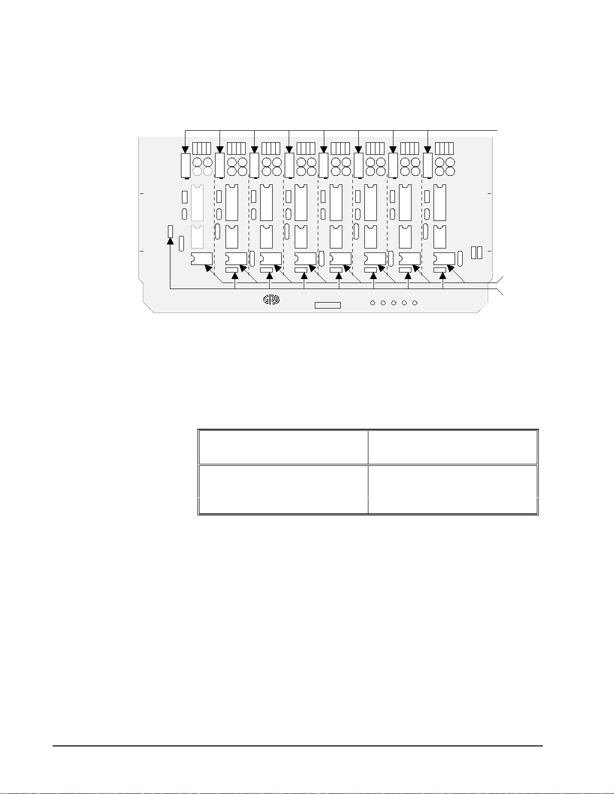
The location of the Meter output gain trims are indicated in the figure above. Note
that the gain trims are covered to prevent accidental adjustments.
NOTE The internal tone generator can be used for alignment. In Chapter 5, see the
“Alignment - Menu 6.1” section for setting tone generator options.
Program Output Adjustments
The following procedure is specific to the analog Program output only and assumes
that meters are aligned correctly.
1. Assign a source with reference tone to all four D/ESAM Program buses.
In Chapter 3, refer to the “Channel Assignment” section for
instructions on Channel Assignment and the “Manual Program /
Preset Configuration” section for details on Program / Preset
Configuration.
2. Bring up the fader(s) so that meters read 0VU (-8PPM).
3. Adjust each of the Program output gain trims to the reference level.
The location of the Program trims are indicated in the figure above.
NOTE The internal tone generator can be used for alignment. In Chapter 5, see the
“Alignment - Menu 6.1” section for setting tone generator options.

Error! Main Document Only.-8 •Alignment D/ESAM 820 User’s Guide
Monitor Output Adjustments
The following procedure is specific to the analog Monitor output only and assumes
that meters are aligned correctly.
1. Assign a source with reference tone to all four D/ESAM Program buses.
In Chapter 3, refer to the “Channel Assignment” section for
instructions on Channel Assignment and the “Manual Program /
Preset Configuration” section for details on Program / Preset
Configuration.
2. In the Monitoring Section, enable MON 1,2,3, 4and MIX OUT.
Ensure that PGM is selected in the Program / Preset section.
3. Bring up the fader(s) so that meters read 0VU (-8PPM).
4. Ensure that MONO, 2-CH and LEVEL/BAL indicators are OFF. In
addition, ensure that Monitor Sub-mix mode is OFF. In Chapter 3,
refer to the “Monitoring” and “Monitor Sub-mix Mode” sections for
more details.
5. Turn both rotary knobs clockwise until the Monitor outputs are at their
maximum output level.
6. Adjust each Monitor output gain trim to match the monitor amplifier’s
input sensitivity. The location of the Monitor trims are indicated in the
figure above.
NOTE The internal tone generator can be used for alignment. In Chapter 5, see the
“Alignment - Menu 6.1” section for setting tone generator options.
Table of contents
Other Graham-Patten Music Mixer manuals
Popular Music Mixer manuals by other brands

American Audio
American Audio Pro-Scratch 2 user guide

Pioneer
Pioneer SVM 1000 - Audio/Video Mixer operating instructions

Solid State Logic
Solid State Logic AWS 924 owner's manual

audiophony
audiophony LIVEtouch20 user guide

T.MIX
T.MIX pm184x owner's manual

Philips
Philips Strand Lighting 100 plus series Operation manuals