D/ESAM 8000 – Installation Guide
System Interconnection 5
System Interconnection
Basic Connections The following is a list of connections you must make to the D/ESAM 8000
system before booting up. Some of these connections are given greater
detail following this checklist.
Basic Connections Checklist:
oConnect power to all 3 components in the system: control panel,
Vadis audio frame and controller chassis.
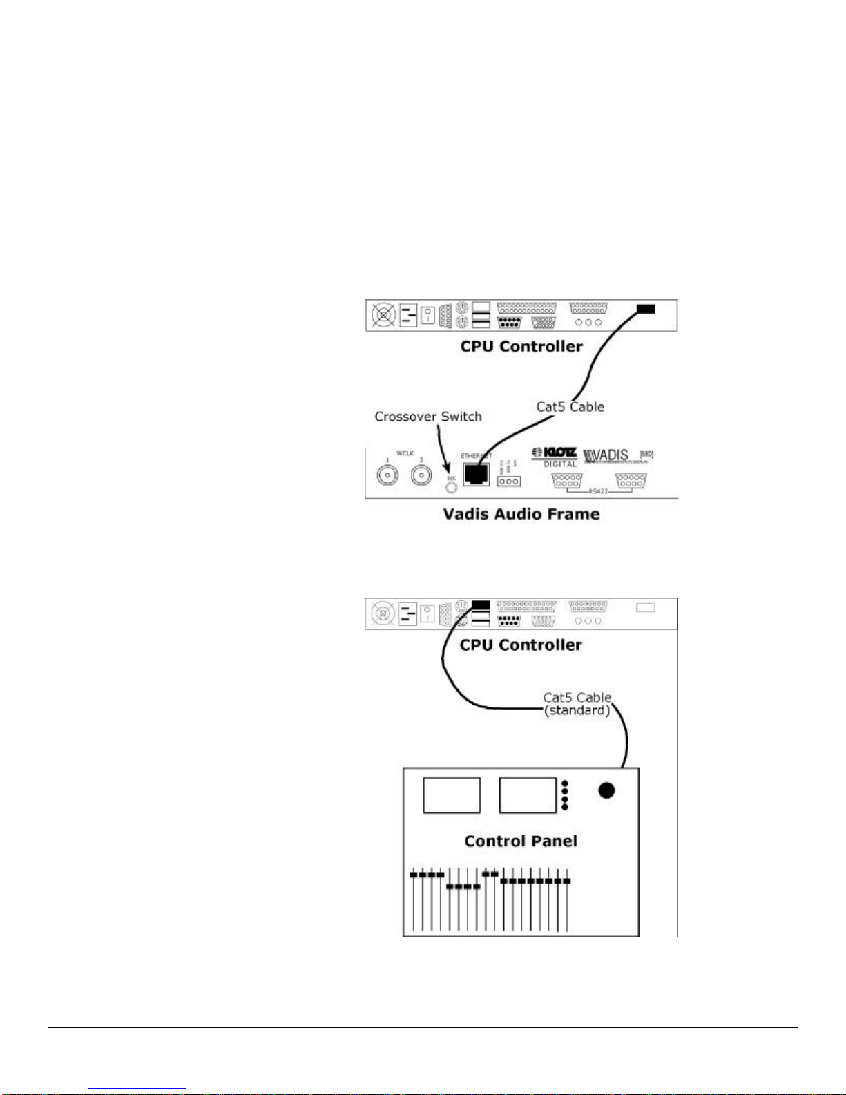
oConnect the control panel to the left Ethernet port on the back of the
CPU controller chassis using the longer standard Category 5, RJ45
Ethernet cable provided.
NOTE: If you are connecting the control panel to an Ethernet hub, use
the crossover Ethernet cable and coupler provided.
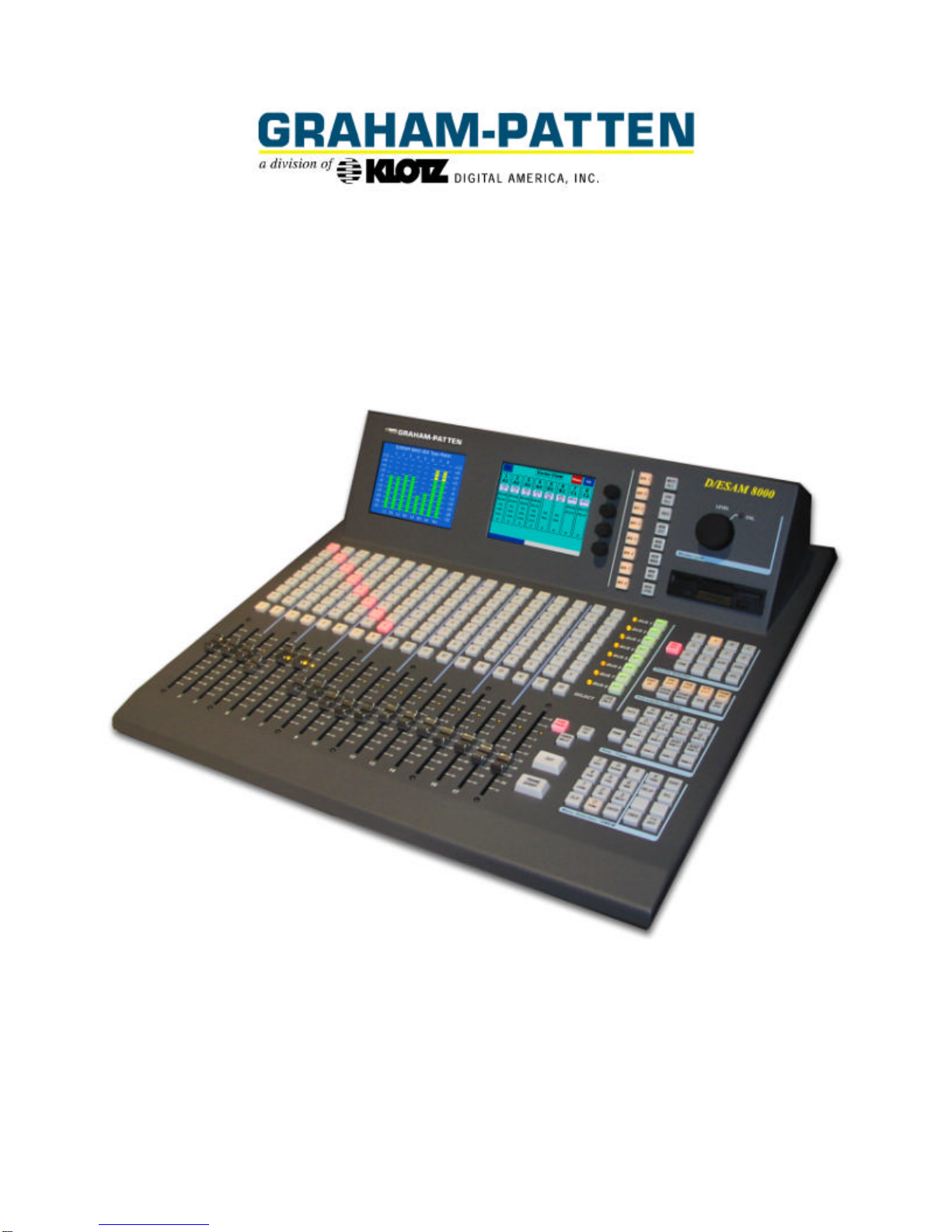
oConnect the Vadis audio frame to the right Ethernet port on the back
of the CPU controller chassis using the shorter standard Ethernet cable
provided.
oConnect your audio sources to the proper audio inputs on the Vadis
audio frame.
These inputs will vary depending on your system configuration. For
specific input connections information refer to the section covering
audio inputs later in this manual.
oConnect your audio outputs to the proper audio outputs on the Vadis
audio frame.
These outputs will vary depending on your system configuration. For
specific output connections information refer to the section covering
audio outputs later in this manual.
oConnect a mouse, keyboard and VGA-compatible monitor to the CPU
controller chassis.
NOTE: These are not included with the D/ESAM 8000 system.
oConnect the edit controller to the 9-pin female D-connector on the rear
of the CPU controller chassis.
oConnect video reference to the jack labeled WCLK1 located on the left
side of the back of the Vadis chassis.
oUsing the BNC to DB9 cable provided, connect one end to the male 9-
pin D-connector on the rear of the CPU chassis and the other end to