10
INSTALLATION
Setting the air extractor mode of operation of
the hood
In the extractor mode air is discharged to the out-
side by a special conduit. In that setting any carbon
lters shall be removed. The hood should be con-
nected to the opening discharging air to the outside
by means of a rigid or exible conduit of
120 mm diameter, which should be purchased in a
shop selling installation materials.
A qualied installer should be commissioned to
make the connection.
Setting the odour absorber mode of operation
of the hood
In this option ltered air returns to the room
through openings in the front of the hood.
In this setting it is necessary to install the carbon
lter. It is recommended to install the air guide
(availability depending on model).
Elements
Kitchen hood consists of the following elements
(Fig. 2):
Installation
Step-by-step appliance installation:
Mounting template
Please refer to mounting template enclosed with
the appliance (g. 3a)
Wall plugs
Using a hammer drive the Ø10 mm wall plugs into
the wholes (A,B) for the xing screws. For the duct,
use 2x6 mm wall plugs in the Ø4 mm holes (g. 3b).
Screw the hanging screws
Screw the 5,5x45 hanging screws in the Ø8 wall
plugs (A,B) that are already driven in the wall. The
screws should protrude from the wall about 5 mm
(g. 3c).
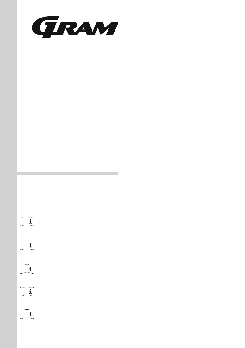
Install the hood
This model is not available with hanging plate.
Hang your product on the slot on the back and then
x it with the screws (g. 3d and 3e).
Install the aluminium duct
Connect aluminium exible duct to outlets on the
product and kitchen wall. Ensure connection will
hold when the product is operated at airow level
(g. 3f and 3i).
Install enclosures.
To install the enclosure use 3,9x x 9,5 at head
RYSB screws (g. 3g and 3h).
a) Lower duct enclosure
b) Upper duct enclosure
Bending the aluminium duct reduces the air ow,
so makes sure there are as few bends as possible
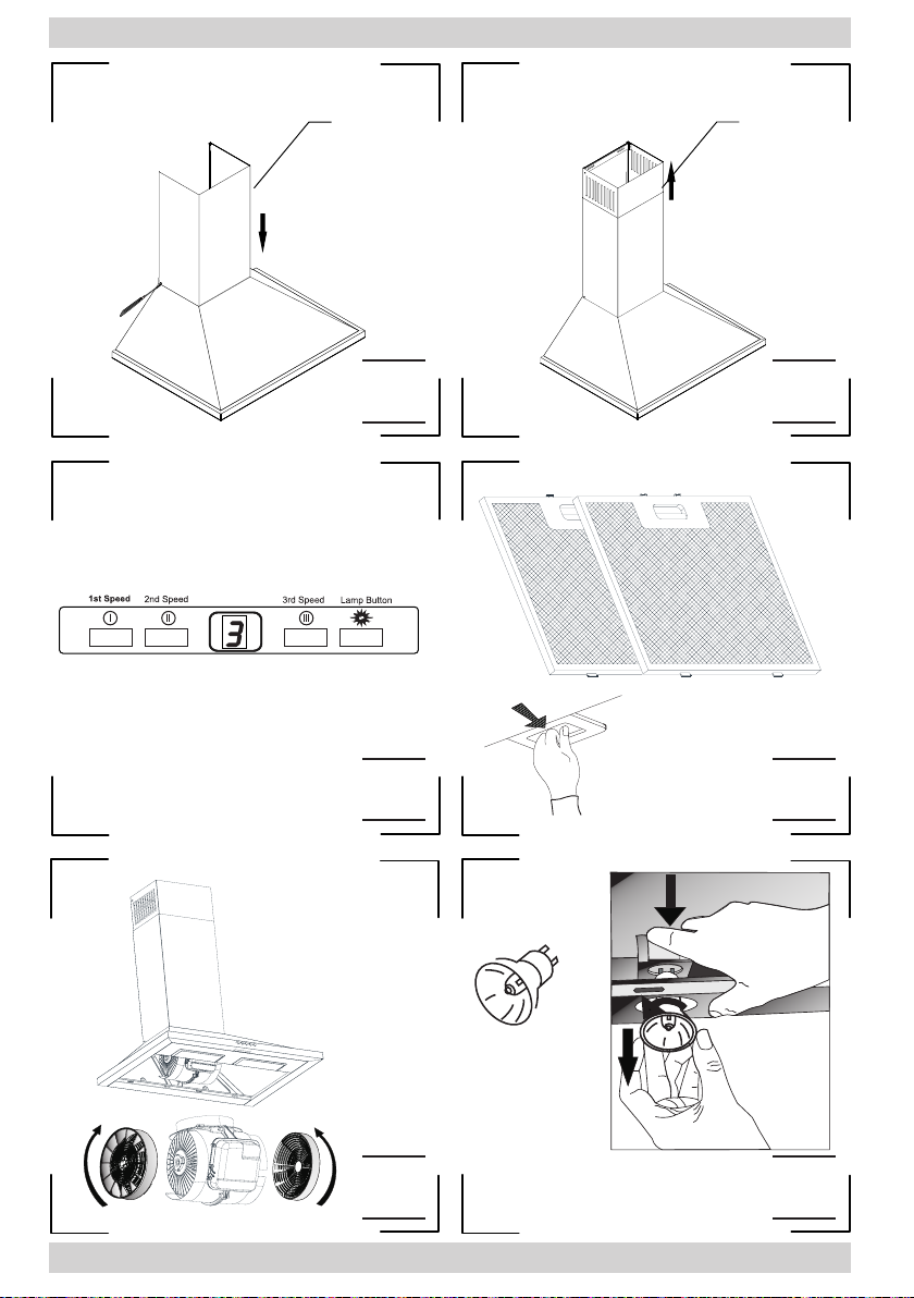
1. Control panel
2. Front panel
3. Aluminium cassette lter (dishwasher safe)
4. Lighting
5. Hood body
6. Upper duct enclosure
7. Lower duct enclosure