Grange Fencing TEA HOUSE PERGOLA User manual

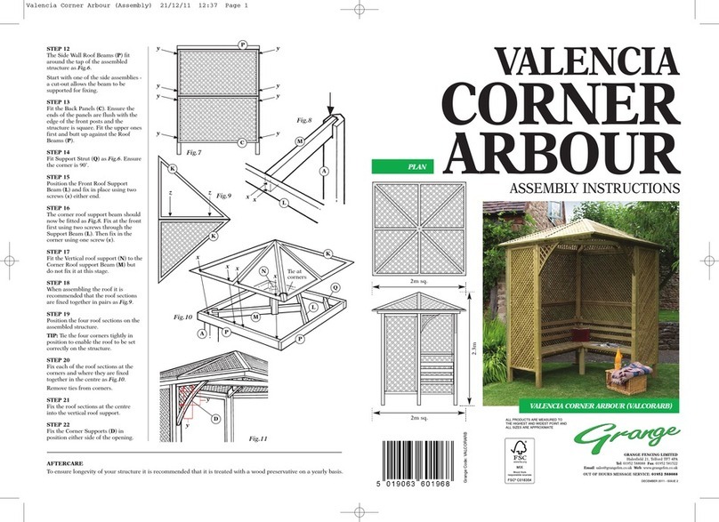
3.5m
2.7m
0.8m
2.495m
SIDE VIEW FRONT VIEW
2.495m
3.60m
PLAN
3.36m
TEA HOUSE
PERGOLA
ASSEMBLY INSTRUCTIONS
GRANGE FENCING LIMITED
Halesfield 21, Telford TF7 4PA
Tel: 01952 588088 Fax: 01952 581522
Email: [email protected]
Web: www.grangefen.co.uk
3.36m
2.63m TOP VIEW
ALL PRODUCTS ARE MEASURED TO
THE HIGHEST AND WIDEST POINT
AND ALL SIZES ARE APPROXIMATE.
By buying products with the
FSC label you are supporting
the growth of responsible
forest management worldwide
CERT No. SGS-COC-000100
© 1996 Forest Stewardship Council A.C.

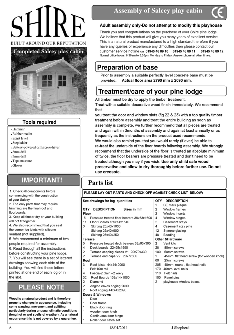
Thank you for choosing this garden structure from Grange Fencing Ltd. In order to gain the most benefit
from it please read the following instructions carefully.
PLEASE READ THE ASSEMBLY INSTRUCTIONS THOROUGHLY BEFORE ATTEMPTING TO ERECT THE STRUCTURE.
THE STRUCTURE IS FOR THE MORE ADVANCED DIY PERSON.
ESTIMATED BUILD TIME - 10-12 HOURS (over two days).
TOOLS REQUIRED (Not Supplied)
POWER DRILL
(+ crosshead screwdiver bit)
SPIRIT LEVEL
TAPE MEASURE
STEPLADDER
SCISSORS OR STANLEY KNIFE
HAMMER
POSTCRETE (for 4 posts)
PARTS LIST
TIMBER POSTS 4
RAFTER (LOWER) 2
RAFTER (UPPER) 2
APEX RAFTER 1
CURVED BEAM 8
CURVED SUPPORT BEAM 2
(LEFT HAND)
CURVED SUPPORT BEAM 2
(RIGHT HAND)
CURVED FASCIA BEAM 2
(LEFT HAND)
CURVED FASCIA BEAM 2
(RIGHT HAND)
ROOF CENTRE SLATS 2x 16
(2 SETS)
ROOF END SLATS 2x 16
(LEFT HAND SIDE - 2 SETS)
ROOF END SLATS 2x 16
(RIGHT HAND SIDE - 2 SETS)
CENTRE SUPPORT SLATS 6
END SUPPORT SLATS 4
SOFFIT BOARDS 2
SHINGLES PACKS 4
EAVES SHINGLES PACK 1
HARDWARE PACK
NAIL PLATE 8
SCREWS - 10 x 3” 8
SCREWS - 8 x 2” 32
SCREWS - 6 x 1.5” 16
NAILS 500
CLOUT NAILS 300
SCREWS - 8 x 100 8
(TURBO COACH SCREWS)
1
2
3
4
5
6
7
8
9
10
11
12
13
14
15
16
17
t
u
v
w
x
y
z
12
3
4
5
6
7
89
10
11
12
13
14
15
16
17
tu
v
w
x
y
z

BEFORE YOU START
•Please ensure that you check all the component parts for quantity and quality before you commence
building the product. Report any missing parts immediately. The manufacturer will not accept any
responsibility for damaged items once any part of the product has been fitted or altered in any way.
•Timber is a natural material and will react to varying levels of moisture content - ie. will swell or shrink.
All of the Timber components are pressure treated green. However, should extra protection be required,
they should be treated using a wood preservative treatment, following the manufacturers maintenance
instructions.
HEALTH AND SAFETY
•Do not overstretch when working from the step ladder.
•Take care and follow the instructions when cutting the shingles.
•No work should be carried out on the roof without the use of a board to distribute the load.
•In order to reduce the risk of suffocation please keep all plastic bags and small parts away from children.
•When you are ready to start, make sure you have the right tools to hand, plenty of space and a clean, dry
area for assembly.
Two people are required to carry out the work.
PREPARATION
Make sure the area where the Tea House is to be erected is clear and level for building the structure.
ASSEMBLY INSTRUCTIONS
STEP 1
Using the ‘footprint’ provided mark
out the area where the
Tea House will be erected.
Prepare holes for the posts allowing
for the concrete.
Each post should be at least 300mm
deep.
NB. The Tea House should only
be erected with the posts
concreted into the ground.
STEP 2
Take two Posts (1) and a Rafter (2).
Position the posts into two of the holes
and fix the rafter into the top of the
posts using the screws (u).
NB. It is preferable for Rafter (2) to be
in the same direction as the Apex
Rafter (4)
STEP 3
Take the remaining posts and Rafter
(2) and assemble in the same manner
in the opposing two holes.
STEP 4
Fix one of the Rafters (3) into the top
of each of the two assemblies to tie the
two together (as fig.3).
300mm
1
STEP 2
TEA HOUSE
FOOTPRINT
2.495m sq.
1
u
1
2
2
3
fig.3
DIRECTION
OF APEX
RAFTER

STEP 5
Fix the other Rafters (3)to complete
the square.
STEP 6
Check the assembly is upright, level
and square. Once this has been
acheived concrete the posts in place.
ALLOW THE CONCRETE TO SET
SOLIDLY BEFORE CONTINUING.
STEP 7
Take two of the Curved Beams (5).
Lay them on a solid flat surface with
the two flats at the profiled end
pushed together (as fig.4).
Using one of the Nail Plates (t)
fasten the two together.
Carefully turn them over and fit
another nail plate to this side.
STEP 8
Repeat Step 7 for the remaining
three pairs of curved beams.
STEP 9
Determine the position of the two
intermediate curved beams along
Rafters (2) (as fig.5).
Mark the positions.
STEP 10
Take the Apex Rafter (4) and mark
the position for the curved beams.
Measure from the centre.
STEP 11
Position one of the curved beam
assemblies across one of the Rafters
(3) (as fig.6).
STEP 12
Locate the Apex Rafter (4) into the
cutout at the top of the curved beam
assembly.
STEP 13
Position one of the curved beam
assemblies at the opposing end of
the Apex Rafter (4) lifting it into
position on the other Rafter (3).
STEP 14
Position the two remaining curved
beam assemblies. Lift them into
place in the upside down position
and rest them on the rafters. Rotate
each one into position at the marked
places.
STEP 15
Check all of the beams are
positioned correctly. Using screws
(v) fix each of the curved beam
assemblies to the apex rafter on
both sides (as fig.7).
=
863mm
864mm
432mm
432mm
863mm
=
5
5
4
5
4
vv
5
5
2
3
1
t
t
t
x
x
x
x
x
1295mm
1295mm
x
x
x
fig.4
fig.5
fig.6
fig.7

STEP 16
Using one of the screws (z)fix one
of the curved beam assemblies to
the rafters (as fig.8).Check the
measurement is 160mm for the
overhang before fixing in place.
STEP 17
Check the dimension for the
overhang and fix the other side of
the assembly in place.
STEP 18
Repeat steps 16 & 17 for the curved
beam assembly at the other end of
the structure.
STEP 19
The two centre curved beam
assemblies are fixed to the Rafters
(2) at the previously marked
positions. Maintain the 370mm
distance from the end of the curved
beams to the centre of the Rafters.
STEP 20
Identify the curved support beams
(these are slightly shorter than the
fascia boards). There should be two
left-handed and two right-handed.
Take one of the beams and fix the
profiled end to the apex beam
345mm from the curved beam. Use
two screws (v) to fix the lower end
to the Rafter (3).
STEP 21
Repeat the procedure for the
remaining three support beams.
ROOFING
The structure is now ready to have
the roof slats fitted. Start with the
centre slats. These span the two
inner curved beams.
STEP 22
Work from the bottom edge up to
the apex using the spacings shown
in fig.9. The last slat should be up
against the apex rafter.
Fix the slats in position using two
nails either side.
Ensure the ends of the slats are
centrally positioned on the curved
beams.
STEP 23
Next, fix one of the end sets of slats.
Use the same spacing as the centre
slats. Fix in position butting the
slats against the centre ones. Nail at
three points, either end and to
where the curved beam is.
z
160mm
345mm
60mm
370mm
z
v
v
370mm
5
5
3
2
4
76
xx
v
x
v
2
70mm
70mm
70mm
70mm
70mm
70mm
70mm
70mm
70mm
70mm
70mm
60mm
15mm
15mm
x
x
x
xxxx
fig.8
fig.9

STEP 24
Repeat Step 23 for the
remaining three sets of slats.
DO NOT CARRY ANY WORK
ON THE ROOF WITHOUT THE
USE OF A BOARD TO
DISTRIBUTE THE LOAD.
STEP 25
The slats that butt up to the apex
rafter require support. Six long slats
plus four shorter ones are supplied for
this purpose. Push one of the slats up
under the top slat previously fixed in
the centre and nail it to the apex
rafter.
STEP 26
Repeat step 25 for the other nine
sections.
STEP 27
The structure is now ready for the
shingles to be fitted. Begin at the
bottom and work up to the apex.
NB. It is recommended that a ‘dry run’
of two levels is laid to ensure that the
correct method and appearance will
be achieved.
STEP 28
Determine the centre of the eaves of
the roof and mark the position.
Take one of the eave shingles and align
the centre with the centre marked on
the roof. An overhang of 30mm should
be allowed at the edge of the roof.
Remember to peel off the protective
plastic on the back of the shingle
before fixing in place with Clout Nails
(f), one at either end.
STEP 29
Lay another eave shingle next to it in
the same way, to the end of the roof.
Trim the shingle to follow the edge of
the roof allowing 30mm overlap. Cut
the shingle and form the corner (as
shown in fig.10).
STEP 30
Repeat step 29 at the other end.
STEP 31
Take one of the shaped shingles and
position it so that the end of it aligns
with the centre of the eave shingle
fixed to the roof. The shaped end
should be approximately 10mm from
the edge of the roof.
STEP 32
Complete the row, fixing the shingles
in the same way as step 21. Trim the
shingles at the end of the roof leaving
an overlap of 30mm
13
17
14
centre
==
30mm
30mm
trim off
excess
centre
10mm
16
y
fig.10
14
131313

STEP 33
Bend the shingles over at the end of
the roof and using Clout Nails (y) fix
in place.
STEP 34
Repeat steps 31, 32 and 33 to complete
this side of the roof. The last row
should cover the top of the apex rafter.
DO NOT WORK ON THE ROOF
WITHOUT A BOARD TO
DISTRIBUTE THE LOAD.
STEP 35
Shingle the other side of the roof
following the same procedure. The last
row of shingles should cover the top of
the apex rafter.
STEP 36
Take one of the eave shingles and split
it into three sections. The shingles are
scored at the correct places to enable
this to be easily done.
STEP 37
The split shingles are used to complete
the apex of the roof.
Starting at one end of the apex rafter,
fix one of the shingles in position to
align with the edge of the fixed
shingles and equally spaced either side
of the apex.
Use two Clout Nails (y) to fix it in
place on the side where the next
shingle will cover them. Remember to
remove the protective plastic from the
back of the shingle.
STEP 38
Continue to fix the shingles until the
apex is completed. The last shingle
should be cut to remove the same
amount that has been covered on
those previously fitted.
NO NAILS SHOULD BE PUT IN
THE FINAL SHINGLE. It may be
necessary to glue this if the bitumen
doesn’t fix it (glue not supplied).
STEP 39
Using screws (v) fit the fascia boards
to the ends of the roof. The fascias
should hide the shingles overlapped
from the roof. It may be necessary to
trim the shingles at the end of the
apex rafter.
STEP 40
Take one of the Soffit Boards (15) and
fix it to the ends of the curved beams
of the roof using screws (w).
STEP 41
Fix the soffit board to the other side of
the roof to complete the build.
y
17
y
y
y
y
v
v
v
v
w
w
v
98
15
w
w

The Grange Tea House Pergola is made of pressure treated and FSC certified timber and as such is guaranteed against rot for a minimum of 15
years. However, it must be remembered that as a natural product, timber is subject to movement and weathering as it seasons. It is not
uncommon for small splits to occur when drying and warping when timber is allowed to dry too rapidly. These will normally go back when
humidity rises. It is nature at work and not considered a fault.
Its colour will also change with time. A retreatment, as required with a proprietary wood treatment is recommended.
CARE OF YOUR TEA HOUSE
OPTIONS
The sides of the Tea
House may be
enclosed if preferred.
(see below)
TEA HOUSE
OPTIONS
The Tea House is
designed so that
the following
options can be
achieved:
OPTION 1
One additional post
plus two 1.2m wide
panels or trellis.
OPTION 2
One additional post +
one 1.8m wide panel or
trellis plus one 0.6m
wide panel or trellis.
1
1
2
3
4
5
6
10
11
12
15
16
17
17
additional
post
additional
post
Table of contents
Other Grange Fencing Garden House manuals
Popular Garden House manuals by other brands
Keter
Keter OAKLAND 1175 user manual

total sheds
total sheds Apex Shed 5ft x 7ft Assembly manual

Palmako
Palmako FR19-2421 installation manual

Mercia Garden Products
Mercia Garden Products 01OVLPA0510PB-V1 Assembly instructions

Best Barns
Best Barns Hampton Assembly Book

Dunster House
Dunster House DUTCH BARN I installation manual

Valkea
Valkea OREGON 2 installation manual

Backyard Products
Backyard Products 16861-F Assembly manual

Solid
Solid S8414 Assembly instructions

Palmako
Palmako FRB28-3226 installation manual

Lemeks
Lemeks Palmako FR40-4040-5 Assembly, installation and maintenance manual
Palmako
Palmako FR40-5742 Assembly, installation and maintenance manual