GRANULDISK GO TECH GD 600 User manual

GD 600
GO TECH
Service manual
Art. nr 16012 03/2005 EN
Granuldisk AB retains the right to make technical changes to the products.
No responsibility is taken for any printing errors.
1.TECHNICAL DATA............................................................................................................6
2. GENERAL DESCRIPTION...................................................................................8
3. FUNCTIONAL DESCRIPTION..................................................................8
4. INSTALLATION.................................................................................................................. 11
5. OPERATIONS CHECK........................................................................................... 13
6.ANNUAL MAINTENANCE............................................................................ 17
7. ROUTINES FOR SHUTDOWN ........................................................... 18
8. HYGIENE and OPERATION DOCUMENTATION ........ 19
9. GD MEMO....................................................................................................................................... 21
10.TROUBLESHOOTING/ALARMS ................................................... 22
11.WARRANTY........................................................................................................................... 25
12. SPARE PARTS LIST................................................................................................... 26
13.WIRING DIAGRAM................................................................................................... 44
Contents
EN

Declaration of Conformity
The Manufacturer:
GRANULDISK AB
Jägershillgatan 15
SE-213 75 MALMÖ, Sweden
declares that the following machinery:
The Granuldisk system GD 600
Basic conception
a) is manufactured in conformity with the Svenska Arbetarskyddsstyrelsens Författningssamling AFS1994:48. This law
conforms with the COUNCIL DIRECTIVE of 22 June 1998 concerning harmonisation of member states` legislation for
machinery (the Machinery Directive 98/37/EG), with particular reference to Annex 1 concerning the essential health and
safety requirements relating to the design and construction of the machinery.
b) is besides the provisions under a) manufactured according to the following directives: the EC Low Voltage Directive
73/23/EEC and the EMC Directive 89/336/EEC
c) is manufactured in conformity with the following harmonised standards: EN 60204-1, EN 55014, EN 60335-2-58,
EN 60439-1, EN 418, EN 294, EN 50081-1:1992 and EN 50082-2:1995
d) is manufactured in conformity with the following national standards and technical
specifications: ELSÄK-FS 1994:7
e) is manufactured in accordance with EN 1717 and fitted with a return flow protection of type AB with an air gap in
accordance with EN 13077.
Malmö, Sweden 01.03.2005
Signed on behalf of GRANULDISK AB
GRANULDISK AB Jägershillgatan 15
213 75 MALMÖ
Telefon: 040 671 50 60
Fax: 040 21 07 21
...............................................
Per Sandberg
(Managing Director)

5
To the user Safety regulations
The GD 600 is a granule potwashing ma-
chine – a potwashing machine for com-
mercial kitchens that is designed for
washing/cleaning things like pots and pans.
This manual is your guide for the correct
installation and use of the GD 600 granule
potwashing machine.
Granuldisk AB recommends that you study
the manual thoroughly to be sure that the
machine is installed and used correctly and
safely.
Ensure that the manual is always available
during the whole life of the machine.
Granuldisk AB accepts no responsibility for
damage to the equipment or other damage
or injury caused by not following the direc-
tions in this manual.
The plastic in the granules is approved for
use in conjunction with food.
The machine uses hot water. Avoid contact
with the skin as there is a risk for scalding.
There is a risk for slipping if granules are left
on the floor.
Formaldehyde,which is dangerous if inhaled,
may be formed if the granules catch fire.
Regarding the handling of detergent in the
manual, please see the manufacturer’s
instructions.

1. Technical data
6
Weight................................................ 343 kg filled machine
Tankvolume...................................... 84 litres
Granules ............................................ 6 kg
Wash power..................................... 7 % granule concentration
Wash water temperature......... 65 °C
Rinse water temperature.......... 85 °C
Rinse water volume ..................... 8 litres/wash cycle. To obtain 3.600 HUE according to ANSI/NSF, 3, 2001,
8 litres is necessary. In other cases the volume can be reduced to 5 litres.
Wash programmes....................... Short 2 min 40 s., Normal 4 min 40 s., Long 6 min 40 s.
Programmes wothout granules are 1 minute shorter.
Time for condensation ............... 1 minute
Design................................................. 2 extractable fittings
Loading volume.............................. 205 litres, width 600, height 650, depth 530 mm
Capacity............................................. 4 GN 1/1, 200 mm deep or 8 GN 1/2, 200 mm deep containers
or the equivalent in pots and other utensils
Max capacity/h................................ 65 GN 1/1 (washing with granules)
Normal capacity/h ........................ 42 GN 1/1 (washing with granules)
Power** .............................................. 400 V (standard), 3-phase, earthed
200, 208, 230, 415, 440 V (options), 3-phase, earthes
Fuse** ................................................. 400, 415, 440 V: 25 A
230 V: 35 A
200, 208 V: 50 A
Frequency ......................................... 50 Hz or 60 Hz
Maximum power ........................... 12,5 kW
Wash pump...................................... 3 kW
Rinse pump ...................................... 0,37 kW
Wash tank element*.................... 9 kW
Rinse tank element* .................... 9 kW
Encapsulation class....................... IP 55
Hot water connection................. 1/2” (DN15) int. 55-65 °C, 3-7 °dH
NB! Osmosis water and totally softened water must not be used.
Hot water pressure/flow ............ 1-6 bar with magnetic valve open / 15 litres/minute
Cold water connection............... 1/2” (DN15) inv. 3 - 10°dH
Cold water pressure/flow .......... 3-6 bar with open magnetic valve / 15 litres/minute
Recommended
extraction capacity....................... 150 m³/h
Outflow .............................................. Pipe Ø 32 mm
Drain ................................................... Required capacity 100 litres/minute
*Not activated simultaneously.
** See the machine’s sign for more detailed information on this machine.
The machine is supplied with a 2,5 m long electrical cable which is connected to the mains box on the wall.
The mains box is not included with the equipment.

'$
REV
GD 600 plus
GD 600 plus
2
#
%
!"
$
#
$
!
%
"
¼
¼
MIN
Installation drawing
7
A = Hot water, G ½” int, 1-6 bar, 15 litres/min., 3-7 °dH
B = Cold water, G ½” int, 3-6 bar, 15 litres/min., 3-7 °dH
C = Drain, Ø 32 mm, Capacity: 100 litres/min.
D = Detergent connection, 24 and 230VAC signals in separate connection box
E = Electrical connection, 2,5 m cable, 400 V (standard), 3-phase, earth, 25 A, 12,3 kW

8
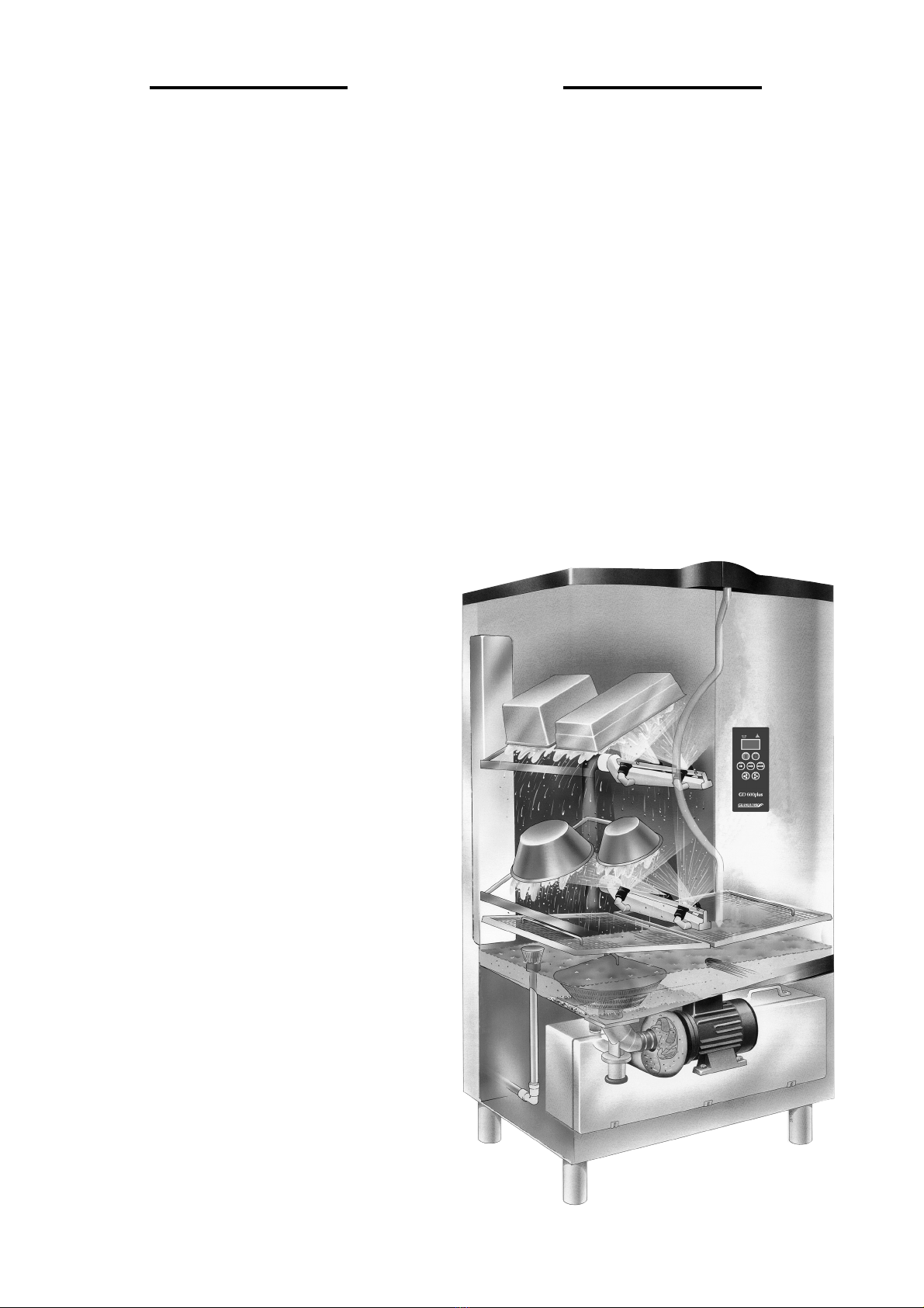
2. General description
The GD 600 potwashing system is designed to cope wth the
requirements of small to medium-size kitchens. The pots are
washed in the machine with a mixture of granules, water and
detergent. All the components are included in the system for effi
cient potwashing. From collection of pots through preparation
to putting the clean pots back on the shelf. The GD 600 is spe-
cially equipped for granule potwashing but also gives excellent
results without granules.
Design
The machine has a capacity for 4 gastronorm 200 mm deep 1/1
containers.There are various fi ttings available.These are designed
to accept the whole gastronorm range from 2/1 to 1/9 trays.
Other kitchenware from ladles and whisks to large saucepans can
also be washed by altering the fi ttings in a simple operation. The
machine is delivered as standard with two fittings.
3. Functional desciption
All operations described in this chapter may only be carried out by
qualified staff.
All electrical components described in this chapter apply to 400-
volt machines. Recalculated electrical values apply to other voltages
(see technical data).
Method of Operation
The machine comprises a wash tank containing water and gran-
ules. The wash pump sucks water and granules from the bottom
of the wash tank through a coarse grid, so preventing large objects
from being sucked into the pump. In the bottom of the tank is
a granule valve which controls whether washing is to take place
with or without granules. The mixture of water and granules is
distributed evenly over the items to be washed via spray pipes
and special nozzles. The water and granules re-circulate in the
system. There are heater elements in the wash and rinse tanks to
heat the water to operating temperature.
After the washing phase there is a separation phase with just
water to rinse away the remaining granules from the items being
washed. Finally the items being washed are rinsed with fresh
water pumped from the open rinse tank, which is entirely sepa-
rated from the water mains network by means of what is known
as a type AB airgap, in accordance with EN 1717, and the rinse
water is pumped out from this via separate final rinse pipes and
nozzles. The final rinse is to wash away any granule residue and
to increase the temperature of the items being washed to guar-
antee a disinfectant cleaning. During the final rinsing phase the
refilling of the machine with water will occur.
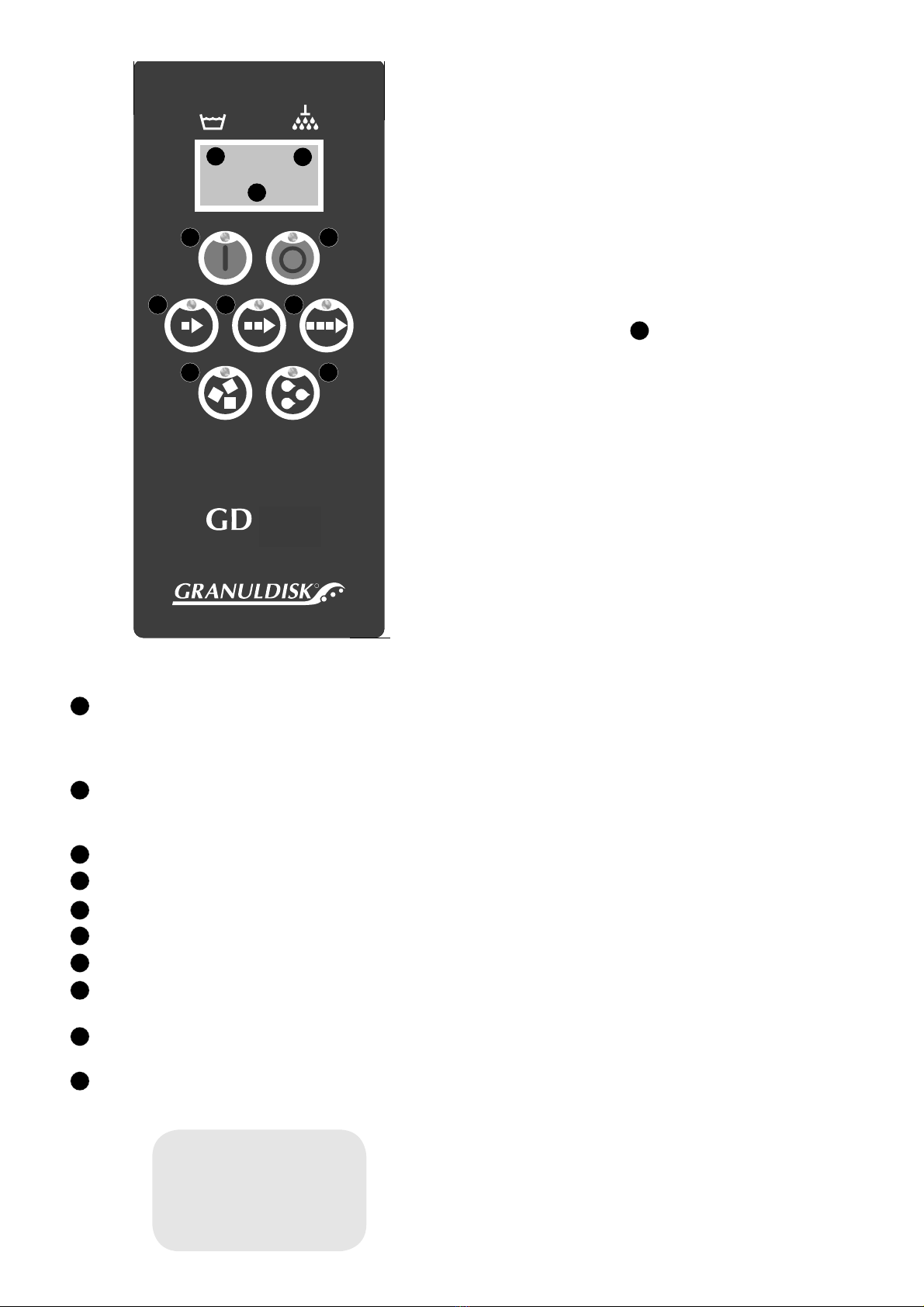
Wash programmes
There are three wash programmes to choose from: short,
normal or long programmes, plus these programmes with or
without granules. If other times or combinations are required,
these can be programmed by an authorised service engineer.
The granules are separated out from the wash water once the
granule cycle is complete. The wash pump stops after 1 minute
of washing without granulate, then the final rinse starts. The
final rinse is set to guarantee a water temperature of 85 °C for
30 seconds.
If the rinse water temperature is too low, the wash time is
extended until it is at 85 °C. The wash programmes without
granules are 1 minute shorter than those with. When the steam
reduction function is used, the hot steam is condensed for 1
minute at the end of every programme.
Wash water system
The wash tank is fitted with a 9 kW heater element to keep the
wash water at the right temperature. The wash tank is filled with
heated water from the rinse tank. A temperature sensor in the
wash tank ensures that the wash water is at the right temperature.
A level sensor at the back of the wash tank maintains a constant
water level. Wash water and granules are pumped through the
two spray pipes and sprayed at high pressure at the items to be
washed. Water and granules are re-circulated in a closed system.
The granules are gradually rinsed out of the items to be washed
during the separation phase and rinsed out of the wash water.
Rinse water system
The rinse tank has a capacity of some 12 litres and is entirely
separated from the water mains network by means of what is
known as a type AB airgap, in accordance with EN 1717. 8 litres
of water are used for every final rinse. The water in the tank is
heated by a 9 kW heater element. The final rinse starts once the
wash cycle is completed. The rinse water at 85 degrees is pumped
and distributed through the nozzles on the rinse pipe. This rinses
away chemical residue while at the same time killing bacteria.
The final rinse jets are divided up on a four pronged final
rinse arm located in the lid together with the wash arm. They
are located so that the rinse water is directed evenly over the
items being washed. The machine is also filled with water via
these nozzles.
Heater elements and temperature sensors
The GD 600 is fitted with one heater element for heating the
wash water and one heater element for heating the rinse water.
The water temperature is regulated by means of temperature sen-
sors, one in the wash tank and one in the rinse tank, and these
emit signals via the control card to the relay switches for the
respective heater elements. The heater elements in the wash tank
and rinse tank operate alternately with priority for the rinse tank
during washing and for the rinse tank in standby mode. In the
event of an error in any of the temperature sensors, the wash
cycle is interrupted and the machine is returned to stop mode.
An error code relating to the temperature sensor is shown in the
display: see Troubleshooting on page 20. There are overheating
protectors in both the wash tank and the rinse tank in order to
prevent damage due to overheating of the heater elements.
Drain valve
At the bottom of the machine, on the front, is a handle for the
wash tank drain valve. This valve is fitted with a sensor which
senses whether the valve is open or closed. If the machine is in an
active process and the valve is opened, the machine switches to
stop mode and an error message is shown in the display.
WARNING!
Only qualified electricians may work
with the electrical unit.
The main fuse shall always be removed
when working with the electrical
components.
Incorrect connections can cost lives.

9
Door sensors and door-locking
There is an automatic sensor on each door. These are connected
in series so that both doors must be closed to indicate doors
closed to the circuit board. Only then can the machine fill with
water and start. The sensor on the right-hand door locks before
filling or starting of a cycle, so that neither door can be opened
during washing.
Alarms and error codes
The GD 600 is provided with a number of alarm functions.
When an alarm is activated, all diodes on the panel flash and
an error message or error code is shown in the display. For more
information on error messages, see the section entitled Trouble-
shooting on page 23.
Steam reduction
Steam reduction is comprised of an ejector into which cold water
is sprayed via a jet. The steam reduction occurs as the steam in
the cabin condenses then circulates through the ejector. The
Steam reduction time is circa 1 minute.
Pumps
The wash pump is of a centrifugal pump type and is custom-
ised for operation with granules from Granuldisk AB. Behind
the pump is a distributor housing which evenly distributes water
and granules to the spray pipes.
The rinse pump is connected to the open rinse tank and used
during the rinse process, as well as when the wash tank is filled.
Granules
The operator can select washing with or without granules. This
is done on the control panel, which is marked with symbols for
water alone or granules, see section Control Panel.
Granuldisk AB’s granule potwashing machines work best with
our specially designed granules. The granules are designed to
give the best wash results and the longest working life for gran-
ules and machines. The guarantee is only valid if granules from
Granuldisk AB are used in the machine.
Granule valve
The granule valve is located at the bottom of the tank and opens
with the help of a solenoid valve. The valve closes with help of a
return spring. The granule valve’s working movements are 20 -
30 mm. The granule valve’s function can be controlled by a com-
puter with the aid of Granuldisk’s service program for authorised
technicians.
Note: While operating the valve function no one should have
their hands near the granule valve where there is a risk of them
getting jammed.
Spray pipe motor
The wash cabin contains two spray pipes operated by the spray
pipe motor. The spray pipe motor is a 230 VAC single phase
motor. Should the operation for any reason be obstructed, there
is a safety guard that stops the machine operating, the washing
cycle is paused and the machine is switched to the stop setting.
The motor is connected to the two spray pipes by means of a
transmission system. These execute a back-and-forth rotating
movement so as to allow the water to strike the entire surfaces of
the items to be washed.
On every wash arm there are four jets. There is also a fixed jet
in the cover. The wash arm motor is located at the rear of the
machine together with the transmission system.
NB! When servicing, engineers should ensure that the power is
shut off so that the machine cannot be started with a risk for
injury.
Distribution box
The GD 600 is supplied with a separate electrical cabinet that
is located on the machine’s bottom plate behind the front plate.
The control system and all electrical components are located in
the electrical cabinet. To work in the electrical cabinet you only
need to unscrew the cover so that all components become acces-
sible. The electrical cabinet can be removed to access other parts
of the machine.
The machine is supplied with 2.5 metres of fitted cable which
leads to the back of the machine. The GD 600 connects to 400V,
3-phase, earthed and is protected with 25A.
Cover plates
The machine is protected cover plates around the machine.
These plates may only be removed during service work.
NB! Always use heavy-duty protective gloves when removing or
replacing the cover plates. Use care if the machine is run without
the cover plates.
WARNING!
Only qualified electricians may work
with the electrical unit.
The main fuse shall always be removed
when working with the electrical
components.
Incorrect connections can cost lives.

Control Panel
(1) START button
This button starts the wash program described in the dis-
play. This button is also used to answer “Yes” to a question
shown in the display window.
(2) STOP button
This button stops all ongoing activities in the machine and
resets any alarms.
(3) Short programme selection
(4) Normal programme selection
(5) Long programme selection
(6) Washing with granules
(7) Washing without granules
(8) Temperature, wash tank: if the figures are flashing, the water
is being heated.
(9) Temperature, rinse tank: if the figures are flashing, the water
is being heated.
10 Wash programme selected
10
R
600
WARNING!
Only qualified electricians may work
with the electrical unit.
The main fuse shall always be removed
when working with the electrical
components.
Incorrect connections can cost lives.
Display
The temperatures in the wash tank and rinse tank are always
shown in the display. How much time is remaining for the wash
programme is also shown while washing is in progress. And
error messages are also shown. How these are to be rectified is
described in section 10 of this manual. All diodes on the panel
flash when an alarm is activated.
One of the following three questions will be shown in the dis-
play, depending on the machine mode at the time:
1. Fill wash tank?
2. Heat wash tank?
3. Choose programme?
Press the START button (1) to start the process indicated.
Starting the machine
The GD 600 fills with water via the solenoid valve for incom-
ing water located on the rear of the machine. A requirement for
filling is that the doors are closed. Filling with water is activated
by pressing the START button on the control panel when the
question “Fill washtank?” appears in the display. The machine
then starts when you select the wash programme and press the
START button. The machine is programmed so that it cannot
be started if the temperature in the wash tank is lower than 65
°C directly after the water has been added. This block function
is set to 60 °C for subsequent starts. The machine may be repro-
grammed only by an authorised engineer.
Note: The GD 600 cannot be started until it is full of water.
GD Memo™
GD Memo is a function which informs the user of the machine’s
most important maintenance requirements. With GD Memo™,
it is possible to ensure optimum wash results, avoid stoppages
under high loads and maintain the lowest possible operating
costs. This function is integrated in the control panel and informs
the user of three actions: changing the wash water, changing the
granules and when the annual service is due.
HACCP Operation and Hygiene documentation
Granuldisk® DocumentationTool, GDTdirect™, is an integrated
function for the documentation of the dishwashing machine’s
operating parameters and critical hygiene control points, HACCP.
This function can be used in two different ways. Operating data
for the last 100 wash programmes run is viewed directly in the
control panel window. An external computer can be linked to the
machine and operating data stored in separate files so that all his-
torical data can be saved. See also section 8 on page 19.
Energy saving – GD Powersave (option)
The GD 600 can be prepared to operate in a central power
restriction system. In this instance, the machine is supplied with
a 24 VAC relay (K50 in the electrical cabinet) which interrupts
the power supply to the two heater elements from an external
24 V signal.
Operating indication – GD Contact (option)
The machine can be supplied ready for the connection of oper-
ating indication, such as an external lamp. In this instance, it is
fitted with a 24 VAC relay (K51 in the electrical cabinet) which
is enabled when the power to the machine is switched on.
10
1 2
3 4 5
89
6 7
1
2
3
4
5
6
7
8
9
10
1

11
4. Installation
All operations described in this chapter must only be carried out
by qualified staff.
All electrical components described in this chapter apply to
400 volt machines. Recalculated electrical values apply to other
voltages (see technical data).
1. On delivery first check that the machine has not been dam-
aged. The GD 600plus is delivered well packaged on a pallet.
Remove all packaging so that the machine stands free on the
pallet. Lift the machine on a pallet lift. Remove the pallet beams
and lower the machine carefully onto its feet. Remove the pallet
by unscrewing the fastening screws.
2. Put the machine in place and adjust the feet until it is level.
Check too that all external screws as well as the screws on the
door’s hinges are tightened.
3. Connect the hot water and cold water supplies. See water con-
nection.
4. Connect the drain pipe on the left to the drain. The drain
capacity should be 100 litres/minute.
Note: The plastic pipe on the right side of the machine is an
evacuation pipe and should not in any way be connected to the
drain.
5. The electrical connections in the electrical cabinet must be
tightened before the input electricity supply is connected. Con-
nect the electrical cable to the main switch on the wall. Check
that the power supply complies with the Technical Data on the
rating plate.
6. Open the water supply and switch on the power. Close the
drain valve which is located on the front plate of the machine.
Close the doors. The display then shows the message: “Fill wash
tank?”. Press the START button to start filling the machine. See
starting the machine.
7. The rinse pump operates when the machine is filling. Check
that the phase sequence is correct as shown in “Checking phase
connection” on page 11.
8. Set the correct user language; see further instructions on page
12.
9. Check that there are no leakages and do an operations check
according to chapter 6 p. 13.
10. Once installation is complete tighten the wash hoses. The door
hinge screws should also be checked and tightened if necessary.
Connecting the water supply
The machine must be connected to a hot and cold water supply.
Use flexible connecting hoses with an internal diameter of no
less than 10 mm. Take care to ensure that you have at least an
extra 500 mm of hose so that you can move the machine for-
wards for servicing. The connections are located on the rear of
the machine. For further specifications see the technical data and
installation diagram. If the water pressure is in excess of 6 bar, a
relief valve should be installed.
Connecting drainage
Place the drain valve in open position (shown by symbols on the
front plate). Connect a plastic pipe, Ø32 mm, between the hole
in the bottom plate and the drain. See the installation drawings
on page 9. The drain capacity must be at least 100 litres/minute.
The machine should not be placed directly over a floor drain. It
is important for the drain to be accessible for cleaning.
Note: The plastic pipe on the right side of the machine is an
evacuation pipe and should not in any way be connected to the
drain.
Connecting to a power supply
The machine is provided with a 2.5 m electrical cable for connec-
tion to 3-phase and earth. See the rating plate for other electrical
data. The main switch is not included in the machine delivery.
Checking phase connection
The wash pump and rinse pump are affected by the phase con-
nection. This is checked in the following way.
1. Close the drain valve which is located on the front of the
machine. Start the machine filling by closing the doors. Check
that the display asks: “Fill wash tank?”, then press the START
button.
2. While the machine is filling up with water, the rinse pump
runs to fill the wash tank. It is difficult to tell from the noise
of the pump whether this is running in the right direction.
Check by carefully placing a cable tie, for example, in the
impeller. Clockwise is the correct impeller direction.
3. If the phases are incorrect, switch two phases on the incom-
ing line.
WARNING!
Only qualified electricians may work
with the electrical unit.
The main fuse shall always be removed
when working with the electrical
components.
Incorrect connections can cost lives.

12
Detergent and rinse agent installation
The machine does not need to be moved but remove the front
plate. The drive voltage and control signals for the detergent and
rinse agent equipment are located in the terminal box (A) on the
front of the wash tank. There are terminal blocks as listed below
in the terminal box:
Connection of detergent and rinse agent
Constant 230 VAC Cable J1-2
Zero 230 VAC Cable J1-6
Connection for detergent
equipment 230 VAC Cable J1-7/D
Connection for rinse agent
equipment 230 VAC Cable J1-1/R
PE
Constant 24 VAC Cable 113
Zero 24 VAC Cable J7-7
Connection for detergent
equipment 24 VAC Cable J8-9/D
Connection for rinse agent
equipment 24 VAC Cable J8-4/R
Tank full Cable J8-5/TF
Emergency stop Cable J8-3
Emergency stop Cable J8-8
For detergent regulation there is a preparation hole (D) to the
right and rear of the cabinet when viewed from the front. The
hole is Ø10 mm.
Note:
- It is very important for the detergent supplier to use the prepared
hole so that no unnecessary holes are made in the machine.
- Some type of angle piece must be fitted when connecting detergent
into the cabin in order to prevent granules from collecting in the
pipe. Alkali sensors are installed there for the design hole (C) in
the front right part of the tank: see figure 1.
There is a connection for rinse agent (B) on the rinse tank (1/8,
internal thread).
Note:
- Granuldisk AB advise against the us of pulse controlled regula-
tion equipment as the detergent concentration becomes uncon-
trollable.
- All dosing equipment must be fitted with a main switch.
Image 1
18455
Language Selection
Follow the steps below to change the language settings for the
machine.
1. Press the STOP button and wait for 3 seconds.
2. Press button 4, “Normal programme selection”, five times.
3. The display shows the following:
4. Press the START button for “Select” and continue changing
the language, or press the STOP button to cancel.
5. The display shows the following:
6. Scroll using the buttons for the short or long programme
to step through the list of languages. Select a language by
pressing the START button.
7. Then press the STOP button to quit programming mode.
Language
English
Select Back
Language
< English >
OK Cancel
!
#$
"
18292

13
5. Operations check
The installer must implement this section together with the
person who is going to be responsible for the machine, e.g. the
restaurant manager or kitchen manager.
The function of the machine is inspected and the most impor-
tant rules for its operation must be reviewed. This ensures correct
handover, which is important for the security of the customer
and the validity of the warranty.
Granuldisk will not be held responsible for any equipment fail-
ure or other damage caused by users failing to follow the instruc-
tions in the manual.
Filling
Check that the overflow filter is applied. Switch on the power and
close the drain valve located at the bottom of the machine, on
the front. Close the doors. The display then shows the message:
“Fill wash tank?”. Press the START button to start filling the
machine. The programme selection diodes flash out of sequence
with the diodes for the wash selection, with or without granules
during filling. If the water is connected correctly, the filling time
should be approximately 7 minutes.
It is possible to check as follows via the control panel that the
correct water level has been attained in the wash tank or rinse
tank:
1. Press the STOP button and wait 3 s.
2. Press button 4, “Normal programme selection”, five times.
3. Use button 3, “Short programme selection”, or button 5,
“Long programme selection” until you see “Value on the level
sensors” in the window. Confirm your choice by pressing the
START button.
The values for the level sensors are displayed in the window for
Wash Tank, Upper Rinse Tank and Lower Rinse Tank, e.g.;
WT: 750
URT: 750
LRT: 750
A value >500 indicates that the level has been attained.
Image 2 Image 3
Checking the temperature
Check that the temperatures in the wash and rinse tanks are 65
°C and 85 °C respectively when the machine is ready to oper-
ate. Heating the wash water from -65°C to 65 °C takes approxi-
mately 55 minutes.
Wash programmes
1. Wash programmes are started by pressing the START button.
The display and programme diodes indicate that a wash pro-
gramme has been selected. If no pre-selected wash programme
is indicated in the display, select a normal programme with
granules.
2. Check that the granulate is added and separated (the noise
level will rise and fall respectively). The granule valve closes
after three minutes so that all granulate can be flushed away
over the remaining wash time. The diode on the START
button goes out when the wash programme is complete.
Granule level check
There should be 6 kg of granules in the GD 600. The machine is
equipped with granule collector (see image 2). The granule level
in these must reach the mark in each collector. If the granules are
left in the tank, the granule level should reach the lower plate of
the granule valve(see image 3). The need for more granules can
be checked regularly by levelling them out.
NB!
- Ensure that only original Granuldisk®granules are used.
- Never use too many granules in the machine.
- We recommend that all the granules are changed several times a year.
Checking dosing
Check with the detergent supplier that the correct amount of
detergent and rinse aid are fed into the machine.
Warranty
For the warranty to be valid, a completed installation report
(page 15) signed by the customer and the installer must be sent
in to Granuldisk AB.

14

15
INSTALLATION REPORT
N.B. The manufacturer warrant
y
will onl
y
be valid when this installation report has
been sent back to Granuldisk AB.
Customer: Date:
…………………………………………………………….
Machine type:
…………………………………………………………………………
Version:
…………………………………………………………………………
E-mail: …….…..….…………… Tel: …...…..……...…… Serial no:
Installation preparations
In-house transport: Water: Drain: Power:
Present at installation - name and position (detergent supplier, chef, staff, etc.)
Delivery damages: Delivery corresponding with packing list:
Machine horizontally adjusted: Connected to water: Drain: Power: Detergent:
Screws tightened (in mains box, box cover, cover plates…): Rinse agent:
Trolley OK (GD900 flow and freeflow):
Water Hot Cold Detergent/rinsing agent Detergent Rinse ag.
Temp. ºC ºC Brand and product
Pressure bar bar Type (fluid, paste, powder…)
Softness ºdH ºdH Recommend. dosing g/l g/l
Function control
Doors locked during filling Filling time (wash tank
)
min
Rotation of all pumps Leakages
All wash programs tested Granule separation
Control of detergent dosing (foaming) PH-value (wash tank)
Steam reduction (condensing unit) Drain
Wash cycle starts only when wash temp reached 65ºC YES / NO Wash tem
p
ºC
Final rinse starts only when rinse temp reached 85ºC YES / NO Rinse temp ºC
Demonstration and training
Start up, preparation of utensils, pots&pans, working method
Loading of wash goods, handling of accessories, programme options
Function of wash programme (sequences), unloading, exchange of water
Handling of granules - collecting, cleaning, filling, exchange
Daily cleaning, annual maintenance
Wall instruction mounted and documentation handed over
GDTdirect™ presented: YES / NO... and software installed in customer's PC
Does the customer need additional accessories, holders? …. which?
Signature of installation engineer: Signature of customer:
GRANULDISK AB, Jägershillgatan 15, SE-213 75 Malmö, Sweden, tel. +46 (0)40 671 50 60

16

6.Annual maintenance check
17
NB! All work described in this section may only be carried out by qualified staff! Ware and tear parts, such as o-rings, seals or nozzles,
are not included in the warranty from Granuldisk AB.
1. Magnetic valve, inlet water Check operation
2. Water hydraulics Leakage pipes and hoses/connections/magnetic valve/ water fi lters
3. Tank level Correct level/Check level sensor
4. Pump/hoses Check for noise/leakage/pressure/hose-clips are secure
5. Final rinse pipes Check nozzles/hoses
6. Spray pipe motor Check operation/unusual sounds
7. Link system, bearings and nozzles Wear and leakage in the spray pipe bearings and/or O-rings?
Blockage or wear in the nozzles?
Nozzles angled correctly?
Binding in the pipes and link systems?
Lubricate ball and socket joints and bearings.
8. Granule valve Check opening and closing functions
Check the sieve cover works and is clean. Check valve washer.
9. Wide drain sieve Is it undamaged, clean and in place?
10. Door switch Check operation 1: Ensure that there is no water in the wash tank.
Close one door and leave the other open.
Check that the machine does not fi ll with water when a programme is selected.
Repeat with the other door.
Check operation 2: Shut both doors and check that you cannot open them while
the machine fills.
11. Doors incl. seals Check leakage/door closing/ door seals/door bearings/control guide knobs
12. Temperatures Check the temperature sensors
Are the probes inserted properly in the wash/rinse tank?
Are the probe screws tightened?
Wash temperature = 65 °C
Rinse temperature = 85 °C
Check the heater elements
13. Rinse tank Check the level sensor
14. Other water leakage Welded joints, washers etc.
15. Distribution box Check cable connections. Programme check (wash times etc.)
16. Control panel Check lamps and buttons
17. Steam reduction unit Check magnetic valve, Clean the whole system
18. Granules Check amount and wear
19. Detergent and drying agent dosing Does the machine dose correctly/ does food fat dissolve/is there foam in the wash
water?
20. Emergency stop (where fitted) Check operation, Located correctly?
21. Drain Check emptying time.
Are there granules in the drain water when emptying?
22. User manual/wall poster Are tehy readily available?
23. Accesories for kitchenware Check that welds etc. are undamaged

Parts to be changed annually
Part no. Part Quantity
6000075.............................Main seal ....................................................... 1
6005035.............................Radial seal ...................................................... 2
14478.................................Clip trim GD 600.......................................... 1
6001121.............................Central strip................................................... 1
6001122.............................Wash jets........................................................ 8
6005012.............................O-ring 9.3 x 2.4............................................. 2
60477.................................O-ring 19.2 x 3.0........................................... 2
These parts are available in a yearly service package with the part number: 18718
Parts to be changed every other year
Part no. Part Quantity
6005159.............................Pipe, wash, short .............................................1
6005021.............................Pipe, wash, long ..............................................1
18451.................................Pipe, final rinse, upper ....................................1
18452.................................Pipe, final rinse, lower.....................................1
13930.................................Nozzle, rinse ..................................................8
13929.................................Nozzle, rinse ..................................................4
13928.................................Nozzle, rinse ..................................................4
60460.................................O-ring 15.3 x 2.4............................................2
14515.................................Connector 1/8” 90° ext...................................2
18285.................................Pipe, in flow rinse pump .................................1
18491.................................Pipe, drain rinse pump....................................1
These parts are available in a yearly service package with the article number: 18721
After changing O-rings 60460, food type
lubricating grease (Granuldisk article no.
14589) must be injected through the
grease nipple.
NB!
7. Routines for a shutdown
18
Routine for storing granules not in daily use.
1. Collect the granules in the machine in the granule collectors.
2. Rinse the granules with plenty of water so all the dirt is
removed.
3. Place the granule collector with granules in a sink or trough
over night. Place them in dishwasher detergent solution, 2ml/
liter.
4. Empty out detergent solution.
5. Rinse the granules with plenty of water. Shake well to remove
as much water as possible.
6. Store the clean granules in the granule collectors.
7. Place the granule collectors in the machine.
8. Ensure that the machine doors are not completely closed so
that the air can circulate.

19
8. HACCP Hygiene and Operation Documentation
GDTdirect™
The Granuldisk® Documentation Tool, GDTdirect™, is
an integrated function for documentation of the potwashing
machine’s operating parameters and critical hygiene control
points, HACCP. The function can be utilised in two different
ways. The operating data for the 100 most recent wash pro-
grammes can be read off directly in the control panel window.
For complete storage of all historical data, an external computer
can be connected to the machine and operating data can be stored
in separate files. The system requirements for the connection of
external computers are Windows 2000 or Windows XP.
Reading Data off the Control Panel
1. Press the STOP button and wait for 3 seconds.
2. Press button 4, “Select normal programme”, 5 times.
3. Scroll with button 3, “Select short programme”, or button
5, “Select long programme”, until “Read operating data” is
displayed in the window. Confirm your selection by press-
ing the START button.
4. Operating data for the most recent programme is displayed
in the window, for example:
050121 15:19 SG 65/85 OK
The information is read as follows:
• Date – 050121 (21/01/05)
• Time – 15:19
• Programme type – S, N, L, corresponding to Short, Normal,
Long programme.
• Selection of washing with granules is indicated with a “G”.
Otherwise this space is blank.
• 65 – indicates the mean value of the temperature in the wash
tank during washing.
• 85 – indicates the mean value of the temperature in the rinse
tank during the final rinse.
• OK – indicates that the rinse water volume is correct in
accordance with the factory values. If the set values have
been changed, NA (not applicable) is displayed instead.
If the wash programme has been interrupted on account of a
handling error or a technical fault, the temperature indication
is omitted and replaced by “Error:” and an error code. See the
example below. For the most frequent potential errors, the
error message is written in plain text. For other errors, please
see the manual.
050121 15:19 SG Error 103
5. To obtain information about previous programmes, you
can scroll forwards and backwards in the list with button 3,
“Select short programme”, and button 5, “Select long pro-
gramme”.
6. To finish scrolling and exit the list, press the START button.
Storing Data on an External Computer
To store complete operating data for the machine, it needs to be
connected to an external computer via a serial cable. Software
is installed on the computer which gradually collects and stores
operating data from every wash programme run.
For storage to take place, the computer has to be switched
on and the documentation program has to be active. Data is
transferred and stored in the selected folder on the computer
after every programme run. This program can be active without
stopping the computer being used normally.
It is also possible to download the last 100 programmes by
selecting “Washer/Get all log data” if the computer has not been
connected. Note: Duplicates may appear in this mode.
Cable Connection
The machine is supplied with a 10 m cable and a serial contact
for connection to the machine and a computer. If the computer
does not have a serial port, a USB/serial adapter can be used. For
information on what is suitable for your computer, contact your
IT dealer. Connect the cable supplied in the start-up kit to the
connector placed adjacent to the detergent connection. Then lay
the cable to the computer via the kitchen’s normal communication
ducts and connect it to a free COM port.
Program Installation
The program is supplied on a CD and is installed as follows:
1. Create and name a folder for the program on the hard disk.
Use “Explorer” in the computer’s office program.
2. Insert the CD and click the program file gdt-direct.zip on
the CD. Save the files in the folder you have just created on
your hard disk.
3. Tip: create a shortcut on the desktop to make it easier to
find the program when you need to start it.
Starting the Program
1. Start the program by double-clicking the program file gdt-
direct.exe in the folder you created on the hard disk or by
clicking the icon you created on the desktop.
2. When the program has started, you have to select the port
to which the potwashing machine is connected. Click Ports
and select the correct port.
3. Then select Washer and then Connect.
4. A window appears on the monitor and you have to select
where you want to save the log file. Select the folder created
under “Program Installation” above and give the file a name.
Tip: name the file after the week or month so that it is easy to find
the operating data stored. Example: “HACCP-w.17-2005”. New
data is saved in the same file after data saved previously until you
choose to give the file a new name. Rename the log file at regular
intervals so that the list does not become unnecessarily long.
5. Data is displayed directly on the computer monitor. See the
picture on the next page. The view has a fixed size that can-
not be changed, and table headings in English. The columns
can be widened by placing the mouse cursor in the table

header and dragging it out.
From left to right, the following information can be read out:
Date; Time; Programme type – Short, Normal, Long; Granules
– G/washing with granules or NO/Washing without granules;
Temperature in wash tank; Temperature in rinse tank; Informa-
tion on final rinse sufficient – OK or NA if the rinse volume was
reduced.
To read out all data, the program must be active and con-
nected to the potwashing machine.
Data Processing
Data can be processed by selecting View in the menu and then
Log file. To read out data saved in older files, use “Explorer” to
find and click the file name in the folder in which the files are
saved. From Log file, the information can be cut and pasted
in, for example, Excel for statistical processing. Saved files can
also be placed on a common server or be emailed to a central
HACCP manager.
20

R
1 2
3 4 5
6 7
8 9
10
9. GD Memo™
GD Memo is an integrated function which informs the user of
the machine’s most important maintenance requirements. With
GD Memo, it is possible to ensure optimum wash results, avoid
stoppages under high loads and maintain the lowest possible
operating costs. This function is integrated in the control panel
and keeps the user informed as follows:
1. Time to change wash water
The “Washing without granules” button (7) flashes and
the message “Change water” is shown in the display. This
information disappears once the water has been changed or
can be reset by pressing button (7) five times. This remind-
er appears after every 20 wash cycles.
2. Time to change granules – to maintain the
wash power in the machine. The “Washing with granules”
button (6) flashes and the message “Change granules” is
shown in the display. This information disappears once the
granules have been changed and this has been acknowl-
edged by pressing the granule button (6) nine times and
the normal programme button (4) once. A granule change
reminder appears after every 2500 wash cycles.
3. Time for annual service
The STOP button (2) flashes and the message “Service” is
shown in the display. This information can only be reset by
an authorised service engineer once a maintenance service
has been completed. An annual service reminder appears
after every 8000 programmes or one year, whichever occurs
first.
7
6
7
6
4
600
21
2

10.Troubleshooting/Alarms
NB! Controls in this chapter may only be carried out by qualified staff.
FAULT CHECK
Machine will not fill with water 1. That the inlet water valve is open.
2. That a programme has been selected.
3. That the doors are closed and the door sensors are activated.
4. That the level sensor is clean.
5. That the solenoid valve works.
The machine will not start 1. The door sensors are activated.
2. The overheating sensor has not tripped out.
3. That the motor sensor QF1 in the electrical cabinet has not tripped out.
4. That the automatic sensor F3 or the glass sensors F4 and F5 in the electrical cabinet
have not tripped out.
5. That the emergency stop is not depressed.
6. That the temperature sensors are intact.
Spray pipe alarm 1.If pots or other things hinder the spray arms’ movement.
2.If the drive system is catching.
No granules when washing with granules 1.That the granule level is correct.
2.If the granule valve is seated properly.
3.That water pressure to the solenoid valve is OK.
4.That the magnetic valve for the granule valve is OK.
5.That the granule valve does not leak.
6. That the dirt filter and constriction is in place.
Granules left on the items to be washed 1.That nozzles are not blocked.
2.That pots are angled correctly.
3.That no foreign material is in the bottom of the granule valve and
that the sealing ring is intact.
4.That the sieve cover is fixed in place.
5.That the granule valve is properly located in its thread.
6.That the SW1 switch on the circuit board is not in the man. position,
(checked by an electrician).
7.That there is not too much foam in the machine while washing.
8.That the spray pipe motor and link system are OK.
9.That the return water pipe is not blocked.
Machine does not wash items clean 1.That the nozzles are not blocked.
2.That the wash water temperature is approx. 65 °C.
3.That detergent dosing is correct.
4.That the right amount of granules are in the machine.
5.That there is not too much foam in the machine.
6.That the spray pipe motor and link system are OK.
7.That the pots are placed correctly.
8. That the protective grid for the pump has not been blocked.
Wash water does not maintain 1.That automatic breaker F1 in the distribution box is in position 1.
the right temperature 2.That the thermistor is undamaged and the temperature is correctly set.
Final rinse water does not maintain 1.That automatic breaker F1 in the distribution box is in position 1.
right temperature 2.That the thermistor is undamaged and the temperature is correctly set.
3.That inlet water is approx. 55 °C.
22
Table of contents
Other GRANULDISK Dishwasher manuals

GRANULDISK
GRANULDISK Granule Combi User manual

GRANULDISK
GRANULDISK Granule Combi User manual

GRANULDISK
GRANULDISK Granule Combi User manual

GRANULDISK
GRANULDISK Granule Gastro User manual

GRANULDISK
GRANULDISK Granule Combi User manual

GRANULDISK
GRANULDISK Lean Wash Center D1 Base User manual

GRANULDISK
GRANULDISK Lean Wash Center D1 Base User manual

GRANULDISK
GRANULDISK Granule Combi User manual