GRAPHTEC F-Mark 2 User manual

Setup userʼs manual
F-Mark2 setup userʼs manual_01E
Read this manual carefully before using the machine.
Keep the manual in a handy place for future reference.
2

CONTENTS
1. Safety Precautions ......................................................................1
2. Terms of use for F-Mark2 ......................................................................2
3. Necessary items in advice for installing F-Mark2 ..............................3
4. Main Specifications ...................................................................4
5. External Dimensions ...................................................................5
6. How to unpack the box of F-Mark2 .............................................6
7. Confirm the accessories of F-Mark2 .............................................12
8. Names and Functions of F-Mark2 .............................................15
9. How to install F-Mark2 ...................................................................17
10. How to attach the Camera to CE7000-40 .............................................20
11. Cable connection ...................................................................23
12. How to install the iMark Plus software .............................................24
13. Notice on using the iMark Plus software .............................................28
14. How to adjust the angle of the Camera .............................................30
15. How to initialize F-Mark2 and CE7000-40 .............................................32
16. How to calibrate F-Mark2 ...................................................................37
17. How to cut test with Test Cut sheet .............................................43
18. How to adjust the cutting position .............................................48
19. Notice on loading media into F-Mark2 .............................................50
20. How to use Stopper Plate ...................................................................52
21. How to use Tail Tool ...................................................................53
22. How to attach the Extension Plate .............................................54
23. How to replace the Suction Cups and Insertion Flap ..............................56
24. Troubleshooting ...................................................................58

- 1 -
1. Safety Precautions
Indicates a potentially hazardous situation if not avoided, could result in death or serious
injuries.
Following these guidelines to avoid to the risk of fire, burns, injury, electro shocks, rupture,
overheating, abnormal odors or smoke.
Always use the recommended AC adapter (EA10682U-120 from EDAC Power) for the F-Mark
feeder to prevent any damage or failure.
The rated voltage is 100-240V AC 50-60Hz.
Do not touch the F-Mark device during a lightning storm.
Do not use the machine / AC adapter in place of high humidity.
Do not overload the power cord.
Do not place heavy objects on, or damage the power cord or plug.
Do not forcibly bend or pull the power cord.
Make sure that the plug is fully inserted in the power outlet. Do not use outlet that is loose.
Do not allow the machine / AC adapter / power plug to get wet for example, by handling them
with wet hands or spilling beverages onto them.
Do not disassemble or modify the F-Mark / AC adapter.
Disconnect the AC adapter and stop using the machine if you notice abnormal odor, heat,
discoloration, deformation or anything unusual while using it.
Indicates a potentially hazardous situation which, if not avoided could result in minor or
moderate injury.
Follow these guidelines to avid the risk of injury, electro shocks, or damages to the F-Mark2.
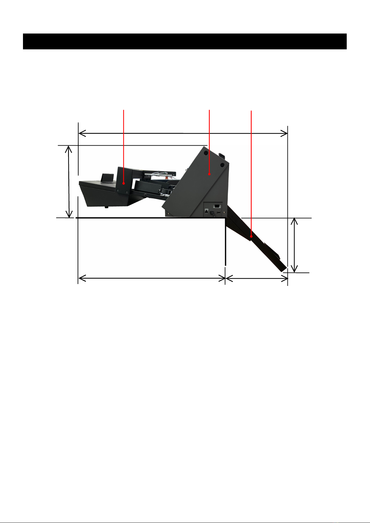
When placing the F-Mark2 device, allow enough table space, take in consideration the vibrations
generated during operations.
Ignoring to do this might cause the product or part of it to fall out of position, resulting in possible
body injury or malfunction of the product.
Do not use or store the product is exposed to direct sunlight, water or oil splashes, salty air or
saltwater, dust or humidity, flammable gas.
Do not touch the paper sheets during operation, the paper edge can cut seriously your skin.
Do not approach with your face to the moving arm and moving paper sheet.
Do not attempt to lubricate the mechanisms.
Do not apply force or object weights on the moving arm.
Lay the power adapter in a position so the green light is visible.
The will alert if the adapter should accidentally go off due to external effects. If for any reason
the green light goes off, disconnect the AC power cord from the wall.
Be sure to grasp the plug, not the cable, when disconnecting the power supply from an electric
form an electric socket.

- 2 -
2. Terms of use for F-Mark2
Restriction on use F-Mark2
F-Mark2 cannot be connected with other cutting plotter.
F-Mark2 cannot be use with Plug-in software and Graphtec Design software with accessories of
CE7000.
F-Mark2 cannot be use with “Simple Mode” of CE7000.
Use F-Mark2 with “ROLL-2 CURRENT POSITION” of CE7000.
Disable the “Sleep Mode” and “Screen Saver” of the operate computer of F-Mark2.
When using the F-Mark2, the holder for pen cannot use be in CE7000.
Use the USB cables which supplied with F-Markk2 for connecting F-Mark2, CE7000, operating
computer and USB-Hub, if use any USB cables, F-Mark2 might not worked properly.
iMark Plus software cannot be load the file name of 2byte characters, use the file name of alphabet
and number.
The files that can be loaded into the iMark Plus software are only the files that can be saved by the
Illustrator 8 format or EPS file that file saved by the Corel Draw.
When installing the F-Mark2 under the strong lighting environment such as spotlight, it may not
operate properly.
Media restrictions to be used with the F-Mark2
Curled media cannot be use with the F-Mark2.
Thick media may not be use with the F-Mark2 because it interferes with Media Separation Flap.
Perforated media may not be use with the F-Mark2 because it is possibility of double feedings.
The maximum number of media that can be load to the Supply tray of F-Mark2 is 200 sheets or 35
mm in height.The thick media cannot be loaded 200 sheets into the F-Mark2.
When the media that under cutting interferes with the media in the Exit tray, remove the media
periodically from the Exit tray.
Cutting area
The cutting are of F-Mark2 as follows.
Minimum distance from front edge of media to cutting line.
Adhesive cut :20 mm (Recommended value :30 mm)
Die cutting :25 mm (Recommended value :35 mm)
Minimum distance from rear end of media to cutting line.
5 mm (Recommended value : 15mm)
Minimum distance from top edge of media to cutting line.
5 mm (Recommended value : 15 mm)
We recommend using recommended values for stable media feeding and stable cutting.
When minimum distance selected, the media may not be fed correctly depending on the media
type and cutting shape.

- 3 -
3. Necessary items in advance for installing F-Mark2
Please prepare the working table of the following size as installation place of F-Mark2.
The required space is 800 mm or more in width, 820 mm or more in length, 420 mm or more
in height. Because the Exit tray hangs 420mm from the top of work table.
Please prepare the tree places electrical outlet, for F-Mark2, for CE7000-40, for operation computer.
F-Mark2
CE7000
Exit tray
313 mm
820 mm
380 mm
420 mm
1200 mm

- 4 -
Media size
Width:297 to 370mm
Length:210 to 500mm up to 700mm with optional
extender
A4,A3,SRA3,Extended A3.
Sheet capacity
Media supply tray:about 200 sheets
(limit depending on media thickness)
Max height:35mm
(depending on type of media)
Sheet weight 350g/m2
Power source AC100V to 240V 50/60Hz
Power consumption 60W
Weight Sheet feeder:10kg Exit tray:4kg
Feeding system Internal vacuum pump
Feeding time 5 seconds
Media separation Air blowers, variable air stream separation
Compatible OS Windows 7/8/ 8.1/10 (32bit/64bit)
Interface USB
Dimensions
(L)x(W)x(H)
Feeder:590x430x220mm
System
Feeder+Cutting Plotter+Exit tray
1200x680x270mm(Height from table top)
Optional parts Extender to 700mm sheets
Stopper for small formats
Operating environment 10 to 35℃、35 to 75%R.H.(non-condensing)
Guaranteed accuracy environment 16 to 32℃、35 to 70%R.H.(non-condensing)
Installation space(L)x(W) Tabletop 820x750mm
4. Main Specifications
The F-Mark2 automatic feeder is part of the CE7000 ASF(Auto Sheet Feeder) system.
It allows automatic operations for contour cutting on printed adhesive sheets or cardboard.
The system is composed by an automatic feeder, a cutting plotter, a dedicated software with optical
detection features and Exit Tray. A mobile lever equipped with vacuum suction cups lift the sheets from
the Media Supply Tray and insert them into the cutting plotter.
The F-Mark2 feeder is equipped with an internal vacuum pump, which is does not require external air
connection.
The system is connected to a computer using USB cable, the dedicate software must be installed on a
PC on Windows OS.
The safety precautions and specification here are referred to the feeder unit only.
For safety precautions and specifications of cutting plotter, refer to the CE7000 userʼs manual.

- 5 -
5. External Dimensions
The tabletop length required to connect and install the F-Mark2 to the cutting plotter is 820 mm.
The width of F-Mark2 when connected to the CE7000-40 is 772 mm.
When F-Mark2 connecting to the CE7000-40, 50 mm space is required on each side of the
CE7000-40 to connect the power cord and USB cable to the CE7000-40.
When installing F-Mark2 and CE7000-40, the Exit Tray expands 380 mm from the working table.
Therefore, when installing F-Mark2 and CE7000-40, secure the enough space so that the worker
does not hits to Exit Tray.
380mm
Exit Tray
CE7000-40 width 772 mm
Exit Tray width 400 mm
50 mm
50 mm

- 6 -
6. How to unpack the box of F-Mark2
1. Open the box of the F-Mark2 with a knife.
2. Remove the packing material from the box.
3. Take out the Accessories box from the box.

- 7 -
4. Take out the Exit tray from the box.
5. Remove the packing material from the box.
6. Remove the side packing materials from the box.

- 8 -
7. Remove the back side packing material from the box.
8. Take out the F-Mark2 from the box.
9. Take out the F-Mark2 from the packing plastic bag.

- 9 -
10. Peel off two Velcro which fixing the Arm cushioning material.
12. Detach the rear Arm cushioning material from the F-Mark2.
11. Detach the front Arm cushioning material from the F-Mark2.

- 10 -
13. Detach the two cushioning materials under the Arm from the F-Mark2.
14. Turn the Blower to the side.
15. Take out the Exit Tray from the packing plastic bag.

- 11 -
16. Take out the Test Cut sheets and Calibration sheets from the Exit Tray.
There are 12 Test Cut sheets and 2 Calibration sheets.

- 12 -
Item Image Quantity
Camera assembly
1
Allen wrench (2mm)
for camera mounting 1
Suction cup
for spare 2
AC power adapter
for F-Mark 1
Power cord
for AC power adapter
(The plug shape varies
depending on the region)
1
1. Open the accessories box with a knife.
7. Confirm the accessories of F-Mark2
2. Confirm the accessories of F-Mark2 with following lists.

- 13 -
Item
Image
Quantity
USB Hub 1
USB cable 1.0m
from USB Hub to Cutting plotter 1
Adhesive cable crip
for camera cable fixing 2
Alignment label
For mounting position of F-Mark2
to CE7000-40
2
CD-Rom 1
Safety Precautions 1
Calibration sheet
(Not in the accessories box) 2
Test Cut sheet 12

- 14 -
Item
Image
Quantity
Stopper Plate
(Not in the accessories box) 1
Tail Tool
(Not in the accessories box) 1
Exit Tray
(Not in the accessories box) 1

- 15 -
8. Names and Functions of F-Mark2
Media Separation Flap : For prevent media double feeding.
Blower : Separate the media by the wind from the blower for prevent media
double feeding.
Blowers Speed : Adjust the blower speed.
Adjustment knob When turning the knob clockwise,the rotation speed of blowers increases.
When turning the knob counterclockwise,the rotation speed of blowers
decreases.When turning the knob counterclockwise to the end,blowers
stops.
Insertion Flap : It assists the insertion of media when inserting the media to the
cutting plotter.
Media Supply Tray : Storing the media to be cut by the cutting plotter.
Side Media Guide : Adjust the width of media in the Media Supply Tray.
Side Media Guide : Adjust the width of Side Media Guide depending on the media width
Adjusting Knob to be used. When adjusting it, make suer that Side Media Guide lightly
touches to side of media. If width of Side Media Guide is narrow or wider
than the width of media to be used may not transport Correctly.
Rear Media Guide : Adjust the rear edge of media in the Media Supply Tray.
Rear Media Guide : Adjusting the position of Rear Media Guide depending on the media size
Adjusting Knob to be used.When adjusting it, make sure that the tip of media lightly press
to the front of inside of Media Supply Tray.
Power Switch : Turn the F-Mark on and off. When the F-Mark turn on,the F-Mark starts
initial operation.
Power Switch
Media Supply Tray
Blower
Side Media Guide
Adjusting Knob
Side Media Guide
Insertion Flap
Media Separation Flap
Rear Media Guide
Rear Media Guide
Adjusting Knob
Blowers Speed
Adjustment knob

- 16 -
Suction Cups
Vacuum Adjusting Knob
Side view
Suction Cups : Pick up media by Suction Cups when inserting the media to the cutting
plotter.
Vacuum Adjusting Kob : Adjust the vacuum force to pick up media.
When turning the knob clockwise, the vacuum force increasing.
When turning the knob counterclockwise, the vacuum force decreasing.
Adjust the vacuum force depending on the media to be used.

- 17 -
9. How to install F-Mark2
1. Peel off the adhesive tape on the back of Exit tray.
2. Put the Exit tray on the working table. Then press the Exit tray firmly on the Working table.
The adhesive tape fix the Exit tray for a short time, it may drop if you do not place the
CE7000-40.
3. Put the CE7000-40 on top of the Exit tray.
There are two ribs on the front of Exit tray. When putting on the CE7000-40 on the Exit tray, insert
the two ribs so that the fit into the gaps of the Front Cover of CE7000-40.

- 18 -
4. Adjust the position the CE7000-40 so that the right edge of the Exit tray is align the 9th line
of the Rear Cover of the CE7000-40, in order to media which after cut by the CE7000-40
drop into the Exit tray correctly.
5. Align the center of Alignment label with the 7th line of the Front Cover of the CE7000-40 and
pasted it.
1
2
3
4
5
6
7
8
9
9th
1
2
3
4
5
6
7
7th
Table of contents
Other GRAPHTEC Printer Accessories manuals
Popular Printer Accessories manuals by other brands

VASTEX
VASTEX E-200 series Assembly and operation instructions

Avery Dennison
Avery Dennison SONIC Knife Operator's and service manual

Kyocera
Kyocera TASKalfa 650c installation instructions

Ricoh
Ricoh Aficio 1045 Series Installation procedures

CAB
CAB A1000 Operator's manual

HP
HP LaserJet CF064A installation guide