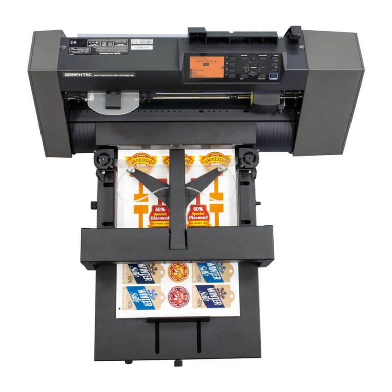
GRAPHTEC F-Mark User manual

ご使⽤前に本編をよくお読みのうえ、安全に正しくお使いください。
お読みになった後、いつでも⾒られる所に必ず保存してください
Service manual
F-Mark2 Service manual_01E

No. Date issued Description of revision Page Edition
1 2019.09.30 First Printing All 01
HISTORY OF REVISIONS

1. External overview ..............................................................1
2. Wiring schematics ..............................................................2
3. How to open the side cover ..............................................................3
4. How to replace the Programmable board ..............................................4
5. How to replace the Pump ..............................................................6
6. Pneumatic circuit ..............................................................11
7. How to replace the Arm assembly .............................................12
8. How to adjust the Arm position .............................................16
9. How to replace the Motor driver board .............................................17
10. How to replace the Blower Fan .............................................20
11. Spare Parts List ..............................................................24
12. Consumables List ..............................................................29
13. Accessories List ..............................................................30
CONTENTS

- 1 -
1. External overview
Blower
Side Media Guide
Adjusting Knob
Side Media Guide
Insertion Flap
Media Separation Flap
Rear Media Guide
Rear Media Guide
Adjusting Knob
Blowers Speed
Adjustment knob
Power Switch
Media Supply Tray
F-Mark2 Top View
Suction Cups
Vacuum Adjusting Knob
F-Mark2 Side View

- 2 -
2. Wiring schematics

- 3 -
3. How to open the side cover
1. Remove the AC power cord from the F-Mark.
And remove the three M3L6 hexagon socket head cap screws from the F-Mark2
using the 2mm allen wrench.
2. Detach the side cover from the F-Mark2.
M3L6 Screw
M3L6 Screw

- 4 -
4. How to replace the Programmable board
2. Disconnect the Flat cable connector from the the Main board.
Disconnect the USB cable from the Programmable board
Flat cable
USB cable
1. Remove the AC power cord from the F-Mark2.
And open the right side cover from the F-Mark2 (referring the “3. How to open the side
cover”.).

- 5 -
3. Disconnect the Programmable board from the Main board.
When disconnect the Programmable board, please care the connector of the
Programmable board so that the it is not deformed and not damaged.
4. Reconnect the Programmable board in the reverse order in which it was disconnect.
Programmable board

- 6 -
5. How to replace the Pump
Prepare the following tools before work.
1: 7 mm wrench for M4 nut.
2: 3 mm allen wrench for hexagon socket head cap screw.
1. Remove the AC power cord from the F-Mark.
And open the both sides covers from the F-Mark2 (referring the “3. How to open the side
cover”.).

- 7 -
2. Disconnect the air tube of the pump from the air tube distributor.
Pump
Air tube
Air tube distributor
When disconnect the air tube from the fitting of air tube distributer,
pull the air tube while pushing the green ring of air distributor fitting.
Air tube distributor
Air tube
Push the green ring

- 8 -
3. Disconnect the pump wiring connector from the Main board.
Main board
Pump wiring connector
Main board
Pump wiring connector

- 9 -
4. Remove the four M4 nats which fixing the pump.
Bottom view
M4 nat
Loosen the nut with 7mm wrench while fixing the screw with 3mm allen wrench so that the
screw does not rotated.
3mm allen wrench
7mm wrench

- 10 -
5. Detach the pump from the F-Mark2.
6. Reattach the pump in the reverse order in which it was detached.
*Insert the air tube firmly into the air tube distributor when inserting
the air tube into the air tube distributor.

- 11 -
6. Pneumatic circuit
Pressure sensor
Electromagnetic valve
Vacuum regulator
Pneumatic hose to the Suction Cups
Main board
Programmable board
Pump

- 12 -
7. How to replace the Arm assembly
1. Remove the AC power cord from the F-Mark2.
And open the both sides covers from the F-Mark2 (referring the “1. How to open the side
cover”.).
Flat cable
USB cable
2.Disconnect the Flat cable connector from the the Main board.
Disconnect the USB cable from the Programmable board
3.Disconnect the power cable connector to the Motor driver board from the Main board.
Power cable
to the Motor driver board

- 13 -
4. Disconnect the air tubes for both sides Suction Cups from the air tube distributor.
Air tube distributor
Air tubes for
both sides Suction cups
When disconnect the air tube from the fitting of air tube distributer,
pull the air tube while pushing the green ring of air distributor fitting.
Push the green ring
Air tube distributor
Air tubes for
both sides Suction cups

- 14 -
4. Remove the four M4 L30 hexagon socket head cap screws holding the Arm assembly
from the F-Mark2 using the 2.5 mm allen wrench.
M4 L30 screw
M4 L30 screw
5. Detach the Arm assembly form the F-Mark main body while care so that cables and
air tubes will not catch on the F-Mark main body.

- 15 -
* After attaching the Arm assembly to the main body of F-Mark2,
make sure that the Arm assembly is attached parallel to the main body of F-Mark2.
* Insert the air tube firmly into the air tube distributor when inserting the air
tube into the air tube distributor.
Arm assembly
6. Reattach the Arm assembly in the reverse order in which it was detached.
Make sure that the tip of the Insertion Flap is parallel to the tip of the
F-Mark2 main body.
If the Arm assembly is not attached paralle lto the main body of F-Mark2,
adjust the Arm position while referring to the “8. How to adjust the Arm position”.

- 16 -
8. How to adjust the Arm position
1. Loosen the six M3 L6 hexagon socket head cap screws (just loosen the screws, do not
remove the screws) on the Arm assembly using the 2 mm allen wrench.
M3 L6 screw
M3 L6 screw
2. Adjust the Arm position.
3. Tighten the six M3 L6 hexagon socket head cap screws while adjusting the Arm position.

- 17 -
9. How to replace the Motor driver board
1. Remove the AC power cord from the F-Mark2.
And detach the Arm assembly from the F-Mark2 main body.
(referring the “7. How to replace the Arm assembly”).
2. Remove the eight M3L6 hexagon socket head cap screws holding the cover
from the Arm assembly using the 2mm allen wrench.
3. Remove the two self tapping screw holding the Motor driver board from the Arm assembly.
Motor driver board
Self tapping screw
Cover
M3L6 Screw
Other manuals for F-Mark
2
This manual suits for next models
1
Table of contents
Other GRAPHTEC Printer Accessories manuals
Popular Printer Accessories manuals by other brands

VASTEX
VASTEX E-200 series Assembly and operation instructions
Avery Dennison
Avery Dennison SONIC Knife Operator's and service manual
Kyocera
Kyocera TASKalfa 650c installation instructions
Ricoh
Ricoh Aficio 1045 Series Installation procedures

CAB
CAB A1000 Operator's manual
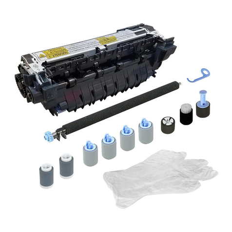
HP
HP LaserJet CF064A installation guide
