2Technical Information
Service Manual
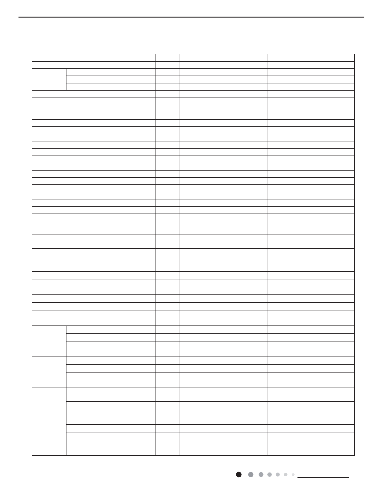
6SHFL¿FDWLRQV
Model GDN40AU-K3EBA1A GDN40AW-K3EBA1A
Product Code CK051024400 CK051024500
Power
Supply
Rated Voltage V Њ220-240 220-240
Rated Frequency Hz 50 50
Phases 1 1
5DWHG'HKXPLGL¿FDWLRQ&DSDFLW\ Pint/D 50 51
Power Input W 570 570
Current Input A 2.65 2.65
Set Humidity Range % 30/80 30/80
Air Flow Volume (H/M/L) m3/h 230/195/170 230/195/170
Fan Motor Speed (H/M/L) r/min 1260/1070/900 1260/1070/900
Fan Motor Power Output W 20 20
Fan Motor RLA A 0.35 0.35
Fan Motor Capacitor ȝ) 22
Fan Type Centrifugal Centrifugal
Fan Diameter Length (DXL) mm ĭ; ĭ;
Throttling Method Capillary Capillary
Fuse Current A 3.15 3.15
Sound Pressure Level (H/M/L) dB (A) 46/43/40 46/43/41
Sound Power Level (H/M/L) dB (A) 56/53/50 56/53/51
Climate Type T1 T1
Isolation I I
Moisture Protection IPX0 IPX0
Permissible Excessive Operating Pressure for the
Discharge Side MPa 4.3 4.3
Permissible Excessive Operating Pressure for the
Suction Side MPa 2.5 2.5
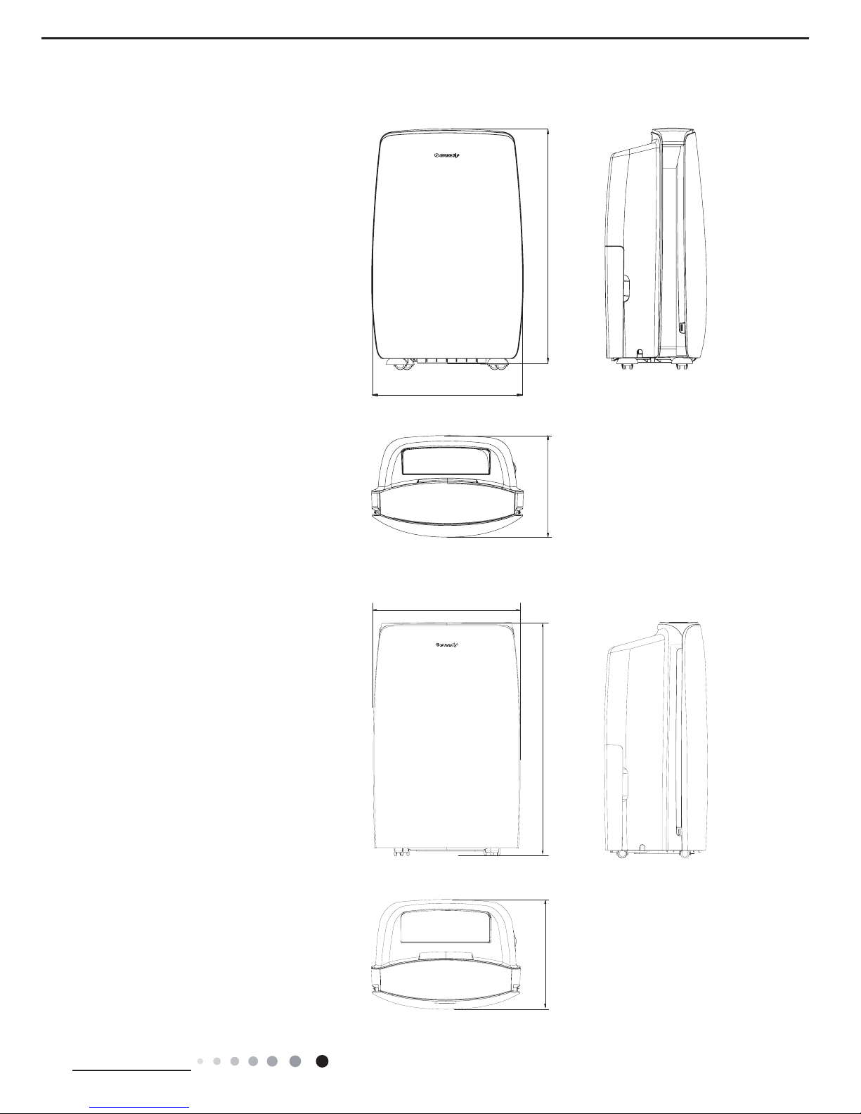
Dimension (WXHXD) mm 390X628X286 396X625X286
Dimension of Carton Box (LXWXH) mm 348X461X655 448X338X638
Dimension of Package (LXWXH) mm 351X464X670 451X341X653
Application Area m248 48
Net Weight kg 22 23
Gross Weight kg 23.5 24.5
Refrigerant R410A R410A
Refrigerant Charge kg 0.31 0.31
Bucket Capacity L 6.5/7 6.5/7
Control Type Electronic Electronic
Evaporator
Evaporator Form Aluminum Fin-copper Tube Aluminum Fin-copper Tube
Evaporator Pipe Diameter mm ĭ ĭ
(YDSRUDWRU5RZ¿Q*DS mm 2-1.4 2-1.4
Evaporator Coil Length (LXDXW) mm 261X228.6X25.4 261X228.6X25.4
Condenser
Condenser Form Aluminum Fin-copper Tube Aluminum Fin-copper Tube
Condenser Pipe Diameter mm ĭ ĭ
&RQGHQVHU5RZV¿Q*DS mm 3-1.4 3-1.4
Condenser Coil Length (LXDXW) mm 261X228.6X38.1 261X228.6X25.4
Compressor
Compressor Manufacturer ZHUHAI LANDA COMPRESSOR
CO., LTD.
ZHUHAI LANDA COMPRESSOR
CO., LTD.
Compressor Model QXA-A071L130C QXA-A071L130C
Compressor Type Rotary Rotary
Compressor Power Input W 630 630
Compressor Overload Protector UP3-B0 UP3-B0
Compressor Oil RB68EP RB68EP
Compressor LRA. A 15 15
Compressor RLA A 2.9 2.9
The above data is subject to change without notice; please refer to the nameplate of the unit.
6SHFL¿FDWLRQ6KHHW


NK3FOGWHD(24)NK3FOGWHD(24)NK3GO User manual")


