INTRODUCTIONINTRODUCTION
The G Lite Tabletop Cannabis Grinder is utilized in your post-harvest processing of hemp and
cannabis. The G Lite destems and grinds, it is the first machine of its kind that gives users
complete control of their finished product with perfect consistency. The G’s low RPM grinding
preserves trichomes and separates stems from material simultaneously.
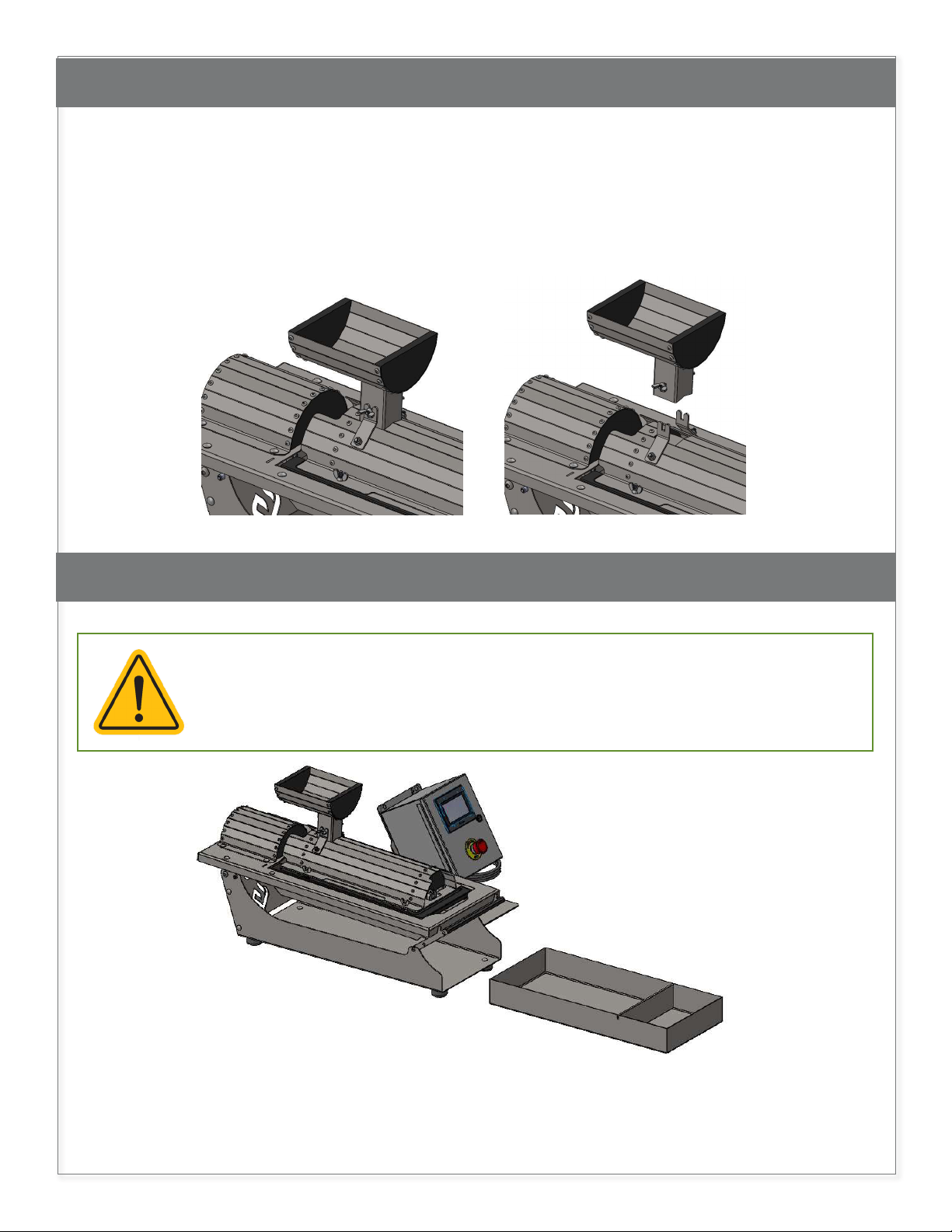
The G Lite is consists mainly of a grinding assembly. It includes speed controls which allow users
to customize the size of the grind, get a consistent mill, and speed up downstream processes.
The assembly comes with the 1/8” screen size. The other screen sizes -- 5/32” and 3/16”-- are
available for purchase. Functions can be manipulated and adapted further by utilizing the
machine’s angle control.
The G Lite’s surgical stainless-steel construction discourages microbial growth and makes it easy
for users to break down and pressure wash the entire unit, minimizing downtime. The machine
has the smallest footprint of any grinder in its class. It can easily be transported to wherever it’s
needed.
Variable Effects Option #1 Option #2
Speed of the
blades:
Machine
Torque
RPMs
Number of
stems in your
biomass
Throughput
per hour
The SLOWER the grinding equates
to higher torque and increased stem
removal. Slower RPMs allow buds
more time to align with the face
of the blade, keeping them intact.
HOWEVER, there would be less
throughput.
The FASTER the grinder rotates, the
less torque it has, and the more often
it will cease (keep in mind, ceasing is
not an issue as long as the machine is
not ceased up for an extended period).
The higher RPM gives the buds less
time to align with the grinding blades
and, in turn, will break more stems,
putting them into the final product.
Humidity level
of material
Number of
stems in your
biomass
Grind
consistency
INCREASING the humidity level of
your biomass will DECREASE the
number of stems in the final output.
This is because dry stems snap and
fall apart instead of bending and
staying intact.
DECREASING the humidity level will
INCREASE the number of stems in the
final output. If your material turns into
a paste, instead of being ground, it is
too wet.
Angle of the
grinding
volume
Number of
stems in your
biomass
Throughput
per hour
INCREASING the angle of the
machine (1, 3, 6 options) will
DECREASE the number of stems in
your final output. This is because the
material will be ground for a smaller
amount of time.
DECREASING the angle of the
machine (1, 3, 6 options) will
INCREASE the amount of stems in
your final output. This is because the
material will be ground for a longer
period of time.
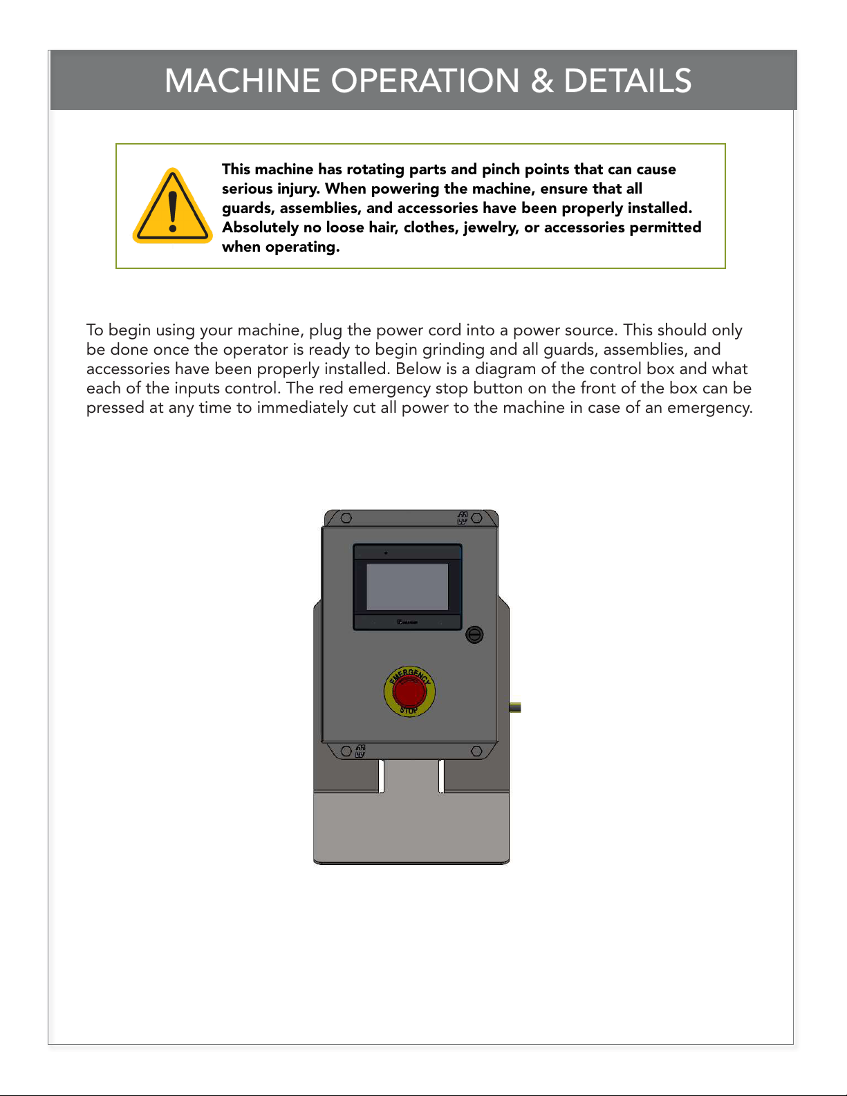
844.DRY.TRIM info@greenbroz.com greenbroz.com
4