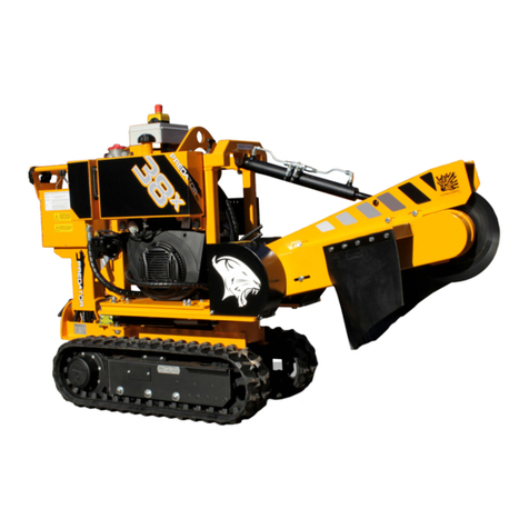
Predator P450 User manual

Operating Instructions
Predator P450 Pedestrian Stump Grinder

Foreword
Thank you very much that you have just purchased our product, the stump cutter F450,
E, H. Our company has been engaged in production of these machines for many years
and we have gained considerable experiences on this field. Quality of our machines is
proven in 20 countries of Europe and Asia we export to.
This manual brings important instructions for users, i.e. instructions for putting the
machine into operation, work safety instructions and operating experiences. You will learn
how to carry out maintenance, repairs and service and who is authorised for doing
checks and other actions.
Your local dealer will give you this manual with instructions for operation and maintenance
upon taking this new machine over. Make sure if you understand everything. If not, do not
hesitate and contact your dealer and ask him for explanation. It is very important for you
and your work safety to understand all instructions given in this manual.
The manufacturer does not bear any responsibility for any claims resulting from
disobedience to the instructions given in this manual.
This manual includes also work safety instructions in various parts of the text. If there is
any work safety rule or instruction in general description then this instruction is indicated
with the following symbol:

Contents
Foreword 2
Contents 3
Product Identification 4
Work Safety Instructions 5
Utilisation 5
General Description 5
Work Safety Symbols 7
Transport of Product 10
Lifting of Product 11
Product Handling upon Delivery 11
Precautions 13
Controls 14
Use 15
Before Operation 15
Transport, Handling and Storage 17
Noise and Vibrations 19
Checks before Putting Machine into Operation 20
Putting into Operation, Cutting 21
Emergency Situations 22
Technical Parameters 23
Maintenance 24
Blades Exchange 27
Auxiliaries 27
Troubleshooting 28
Waste Disposal 29
Warranty 29
Maintenance and Service 29

Product Identification
Our product is identified with a serial number stamped both on the type plate and on the
chassis. Further on the combustion engine installed on our machine is identified with a
separate type plate.
Upon take-over of the product we recommend you to fill required data in the following
form concerning the given product and your dealer.
Type of product: …………………………………………..
Serial number of product: ……………………………………………
Engine type: …………………………………………...
Serial number of engine: ……………………………………………
Dealer's address: ……………………………………………
Address of authorised service: …………………………………………..
Date of delivery: …………………………………………..
Warranty expiration date: …………………………………………...
Interruption of warranty period: …………………………………………...
The type plate is placed in the lower part of the machine under its controls.
The type plate includes:
-manufacturer's address
-type
-serial number
-engine type
-weight of machine
-CE identification symbol

Work Safety Instructions
Utilisation
This machine is designed for cutting of a stump, i.e. its above-ground part and in a max.
depth of 20 cm under the ground level. This machine cannot be used for cutting of dozy
stumps which could be released and pulled out under the blades. Avoid any cutting if
there can be stones, metallic objects etc. hidden in the stump and also bucking of free
stems.
Generally
-This machine can be operated only by an operator that is over 18 yrs old,
physically and mentally capable and demonstrably instructed with its operation.
-Keep this machine beyond children's and unauthorised person's reach.
-The operator of the machine is fully responsible for any injury or damage caused
to the third persons within the operating reach of the machine.
-Before working learn all functions of the machine and its particular controls.
-At work in residential zones use the machine in accordance with regulations of the
local authorities to avoid disturbing local inhabitants.
-This product is not designed for motion on public roads. It can be transported
only on a such trailer which is designed for this purpose.
-While working wear always personal protective aids - safety helmet with protecting
shield, protective gloves, working shoes, industrial protective clothing properly
buttoned.
-This manual includes also some common troubles and failures which could occur
and which are easy to be remedied by an instructed person. Other problems and faults
should be announced directly to the manufacturer who is always ready to helpyou.
-It is not allowed to do any technical changes or any actions which are neither given
in this manual nor allowed by the manufacturer. The machine, not correctly installed
or adjusted, may run without problems now but in the future it could damage any of
its important parts.
-Do not put any objects or tools on the machine.
-The manufacturer does not bear any responsibility for any damages or injures to the
third persons or to other equipment resulted from disobedience to instructions given
in this manual.
-When turning off the machine do not leave the switch key in the ignition box.
-When handing the machine over make sure if all controls, guards and other safety
elements are complete.
-Never remove guards and other safety elements. They serve for your safety.

Work Safety Symbols
This article introduces work safety symbols (pictographs) used on the machine. Under the
figure there is its position on the machine. These work safety symbols warn the operator
against risks connected with the machine use. Your respect to their meaning is a
precondition for your work safety.
The user is obliged to keep all the work safety symbols legible, clear and undamaged. In
case of any damage or illegibility ask your local dealer or an authorised service for a new
corresponding pictograph.
1 2 3 4 5 6
Read the operating
manual before use.
While working
always use
personal protective
aids.
Always follow the
manual while
maintaining, servicing
or repairing the
machine and take the
key out of ignition.
Warning! The
electric current is
present on the
machine.
Alwaysuse
supportswhile
maintaining,
servicing or
repairing the
machine
Maximum gradient
allowed is 11°.
Rollover hazard.

7 8 9 10 11
Start the machine
with the switch
key only. Do not
short circuit the
contacts.
Warning! Fuel is
flammable! Keep
open fire away!
Warning! Hot
parts of the
exhaust manifold.
Warning! Rotating
part. Hit and pull-
in hazard.
Lashing points.

12 13 14 15 16 17
Warning! Lower
extremities injury
hazard.
Warning! The
cutting head is
running out.
Warning! Rejected
objects hazard. Keep
away.
Warning! Do not
interfere in V-belt
gearing.
Warning! Close all
guards before
starting the
machine.
Warning! Do not
step into the
operating space of
the machine while
in use.

Transport of Product
-This product is delivered completely mounted and attached to a wooden pallet. While
handling use a lift truck or lifting means. While lifting the machine up you may use a
crane (suspension in the given lashing points only).
-The manufacturer delivers the machine shrink-wrapped. The protective foil
protects the machine against weather effects but in no case against mechanical
damage, fall
etc. The protective foil is recyclable, use it according to valid local regulations.
While putting the machine aside (e.g. at reloading) we recommend to place it under a

While unloading put the product always on a flat and firm bottom.
It is not allowed to put it on a labile base.
Do not put any objects or tools on the machine.
Lifting of Product
-For lifting it is possible to use a crane (clamp) with suspension at the given lashing
points marked with chain symbols.
-WARNING! While lifting with a crane always use the transport brace which is
delivered with the machine. If the grips are not supported it may cause damage of
the fuel tank or of the engine while lifting.
-Lift up the machine only in the above mentioned ways. Any other way of lifting is
not allowed.
Fig. 1 Fig. 2

-Keep the given intervals for checks of bolted joints.
-Always after work clean all parts of the machine.
-Any servicing can be done only if the machine was put out of operation, the
switch key was pulled out of the ignition box and the battery was disconnected.
-Keep all parts clean, especially cooling ducts of the engine and parts related to
the fuel tank.
-Fill up the fuel tank before working and only if the machine is turned off. If it
is necessary to fill it during a working shift then do not fill it if the tank or engine is
still
hot.
-Do not fill the tank while the engine is running.
-Do not start if some fuel has been spilled.
-Do not use petrol as a cleaning agent.
-Keep open fire away while filling the tank.
-Keep the machine beyond a reach of open fire.
-Any transport of persons or of any load on the machine is not allowed.
-Some parts of the machine can be extremely hot while in operation. To avoid any
burn risks do not touch these parts when the engine is still running or when having
just stopped the engine.
-Turn off the switch key always before battery disconnection.
-Disconnect the battery always before any maintenance on the machine.
-Avoid any random start - disconnect the plus pole of the battery.
-Do not touch live wires while the machine in use.
-Do not let the engine running in a high speed unreasonably.
-Do not change the engine setting, especially its speed regulator.
-Be careful while battery handling.
-Warning! The battery contains sulphuric acid that could cause burns.
-Do not start the machine in closed or ill-ventilated spaces.
-Do not use the machine under conditions of low visibility.
-Do not use the machine without prior reading this manual.
-Do not carry out any repairs that are specified for authorised services only.
-Do not carry out any repairs where its solution exceeds your experiences.
-Pay maximum attention to all instructions given in this manual relating to the type

Fig. 1 - Front brace - the brace end, if lifted, serves as a guide for the clamp
Fig. 2 - Transport brace - the point for the clamp suspension
Handling of Product upon Delivery
Upon delivery unload the machine from the transport pallet as follows:
-Set the front brace downward and lock it.
-Cut the binding band carefully. Be careful, the band is tightened up and after cutting
its both ends may shot out. While cutting use protective gloves.
-If a lifting device is available lift up the machine and remove the transport pallet. Then
lower the machine down.
If no lifting means are available, further on proceed as follows:
-Set the front brace down and lock it.
-Cut the binding band carefully. Be careful, the band is tightened up and after cutting
its both ends may shot out. While cutting use protective gloves.
-Remove blocks under the cutter wheels.
-Remove the transport brace, set the grip and lock it with a relevant pin and a cotter.
-Put the blocks in front of the pallet in the wheel spacing, in direction of supposed
travel.
-First turn the front brace and, while holding the grip, tilt the rear brace.
-Before pushing the machine off the pallet make sure if the space for the machine is
free enough.
-Warning! Having pushed the machine it will "move out" faster because of its weight.
The stump cutter, type F 450E, is delivered with an electric driving unit. While unloading
proceed accordingly, as mentioned above.
-Check up the locking pins in the bottom position (see chap. "Travel of Machine").
-Both pins must be in the locked position.
-Connect the plus pole of the battery.
-Push the button for travel and move the machine off the pallet.

1
The stump cutter, type F 450H, is delivered with a hydraulic driving unit. While unloading
proceed as follows:
-Check up the locking pins in the bottom position (see chap. "Travel of Machine").
-Both pins must be in the locked position.
-Fill the fuel tank with petrol (approx. 2 litres). Check up the hydraulic oil level
(small oil cup close to the fuel tank)
-Connect the plus pole of the battery.
-Start the engine and set its idle speed.
-Put the control lever in the front position and go slowly off the pallet.
Precautions
The machine is provided with safety guards protecting against any touch of the rotating
parts (hit and pull-in hazard) and against hot parts (exhaust manifold). The guards are
fixed, bolted down and solid, only the guard over the exhaust manifold is perforated.
The machine can be operated from the operating side, i.e. behind the control grip with
relevant controls.
Operator's place
While working the machine is moved manually, the model F450E is available with an
electric travel gear, the model F450H is provided with a hydraulic drive.

The combustion engine drives the cutting head. Under the lower grip there is the "dead
man lever" installed which must be pushed down while working.
Caution !!! This machine can be started if this control lever is not pushed down.
Having turned off the cutting operation the turning head is braked by the engine while
running out (models F450 and F450E).
The model F450H is equipped with an electromagnetic clutch transferring its torque to the
cutting head which turns also the head drive off.
Caution !!! Having turned the clutch off the cutting head is freely turning out. Any
handling/motion is allowed after dead stop of the cutting head. Any braking of the head is
strictly forbidden.
Controls
The stump cutter can be operated by means of controls on the control panel and under
the grip.
Control panel - F 450 Control panel - F 450E
1. ignition box 6. directional brake left
2. dead man lever 7. choke lever
3. button of electric travel gear 8. accelerator lever
4. operating grip 9. pin of grip position setting
5. directional brake right 10. case for operating manual etc.
1
2
4
1
2
3
4

1. ignition box
2. dead man lever
3. button of electromagnetic clutch for
cutting head drive
4. operating grip
5. brake
6. choke lever
7. accelerator lever
8. travel control lever
9. pin of grip position setting
10. case for operating manual etc.
Control panel - F 450H
Use
1
9
6
7
58
1
4
1
3
5
6
2
7
8
9

Before Operation
-Before the first putting into operation check up the machine for accidental
damages and completeness after its transport and storage.
-Check wrapping for oily spots, if any, check oil charge level.
-In case of any damage contact your dealer or an authorised service.
-For replacement use always original spare parts only.
-Before transport the fuel tank was put under the machine on the pallet. Remove the
paper wrapping and put the tank on the base plate, with its slope toward the
operating side and fix the tightening clamp. Fix the clamp from under with the nut
M8.
-Fit the elastic hose from the filter onto the suction pipe.
-Having fit the hose tighten up the hose clip.
-Check the engine oil level with a dipstick and refill if necessary. The oil level must
be between both marks (MAX and MIN).
-Check tightening of bolted joints, especially rotating parts and completeness of
other parts.
-Fill the given fuel into the tank, min. volume of 4 litres. The tank has its max. capacity
of 18 litres.
-The fuel to be used is unleaded petrol NATURAL 95.
-Make sure that nobody is within a reach in front of the cutter.
-While handling protect the cutting blades against any shock.
-Do not lean the cutter against the ground or against any other object. Support the
cutter with the front and rear brace - set the braces in the bottom position.
-Use both directional brakes/one brake to block any motion of the machine.
At the first start there is more air in the intake manifold and on this account the engine
may not roar to life immediately when turning the switch key for the first time. Do not
crank the engine for a longer time than 10 sec. We recommend to use the choke before
the first (cold) start.
Be aware that the engine is equipped with a fuel pump which delivers the fuel at every
starting. Never fill the filter and the relevant manifold with the fuel.

Dipstick
Air filter
Fuel tank
Hydraulic oil buffer tank
Engine oil filler
Fuel filter
-After a short start make sure if the fuel filter is filled with the fuel. You should see a
darker fuel level in the filter body. If the fuel level is under 3/4 filter volume crank the
engine with its switch key once more. Keep an interval between two starts of 30 sec.
at least.
-Having started increase the engine idling speed and set the choke slowly in the
OFF position.
-WARNING!!! Just after the start the cutting head starts turning (models F450 and
F450E).
-Increase the engine speed to 50% and let the engine running for about 1 minute.
-Do not leave the machine unattended.
-After a short initial run slow down with the accelerator lever and turn off the switch
key in the ignition box.
-If you heard any strange noises or vibrations during its initial run turn off the
cutter immediately and contact an authorised service or directly the manufacturer.

Transport, Handling and Storage
-This machine is not designed for motion on public roads. It can be transported
only on a such trailer which is designed for this purpose.
-After loading fix the machine properly on the loading surface.
-For loading or unloading use suitable lifting means with min. carrying capacity
of 250 kg.
-Lifting clamps should be fixed in the marked lashing points only.
-If using a ramp for loading or unloading then its surface must be steady enough with
no slippery surface.
-Such ramp could be with a max. gradient of 20%. In case of such gradient it is
better if other two persons will assist you with such handling.
-In case of the type F450E or F450H make use of its travel gear. In this case both
wheels should be secured with a relevant pawl against free rotation.
-Any handling is allowed on the terrain with its max. gradient of 11 o.
-Any work with the cutter is allowed up to the slope of 11 o.
-In case of any handling the cutter F450 on the rolling ground we recommend other
two persons to assist you because of its weight.
-Be careful when going up or down the hill. We recommend to push the machine
forward.
-When going downhill be careful if using the brakes. Any rapid braking action of one
wheel only will turn the machine around the blocked wheel.
-Always transport the cutter if the cutting head is stopped and the switch key is in
the "0" position - valid for models F450, F450E. The model F450H should be
transported
with its released clutch of the cutting head (stopped).
-It is strictly forbidden to move any model with its cutting head still turning.
The pawl in its locking position, The pawl pulled
out,
the wheel is blocked the wheel turns
freely

The modification F450E is equipped with the electric travel gear for easier handling off
roads. If you decide to make use of this travel gear, proceed as follows:
-Lock the pawl of both wheels, i.e. turn it in the locking position.
-Let the switch key in the "0" position and push the rocker switch for the backwards
or forwards motion and the machine goes in the given direction. Release the button
and the machine stops.
-We recommend to use this electric gear especially for loading and unloading
of the cutter.
-If both wheels are locked with the pawl then any wheeling is limited
Handling the model F450H
See: Handling the model F450E
Use the brake to block the cutter against unwilling motion.
Storage of cutters in rooms protected against water
-Before storage pull out the switch key from the
ignition box and keep the key separately.
-Before storage clean all parts of the machine.
-Clean especially oily spots.
-Exchange all damaged or worn parts. Use always
original spare parts. For the spare parts contact
your dealer or authorised services.
-Before putting machine aside for a longer time
check up the tyre pressure.
-Before putting machine aside for a longer time
change the engine oil and the filter element. The
filter body is located under the tank. Under the filter
body there is the engine oil discharge hole.
-Discharge the used oil into a special bin. Give the
used filter element to disposal in accordance with
laws and local regulations.

-Remove any spilled oil and clean all oily spots properly.
-Tilt the front and rear brace to avoid the machine rollover around the axle.
-Always put the machine aside on a flat and solid flooring and block against unwilling
motion.
-Do not put any objects or tools on the machine.
-Store the fuel canisters separately.
Noise and Vibrations
Operation of this stump cutter brings following emissions:
NOISE - L
A = 89,3 dB
VIBRATIONS - final balanced value at - idle speed: 1,70 ms
-2
- max. speed: 1,15 ms
-2
- at work: 1,58 ms
-2
While working the persons who operate this machine are obliged to use protective aids
active against noise in level of A 90 dB.
Checks before Start
-Before putting into operation check up the machine for completeness.
-Check up all bolted joints, especially on the cutting head.
-Check up the cutting blades for completeness. If one of them is damaged change it
immediately. It is strictly forbidden to use the cutter with its damaged cutting head.
-If some abrasion occurs change all the blades on account of balance of the cutting
head.
-Be careful at this change, the blades are of the left and right types.
-Check up the V-belts for their right tightness.
-Check up the tyre pressure.
-Check up the hydraulic oil level in the buffer tank. The oil level must be kept on the
mark. While warming up the oil volume grows and oil level goes up.
-In case of oil exchange in the axle then deaerate the system. The relevant bleeder
screw is located under the frame.
-Check up the oil level in the differential gear unit.
Table of contents
Other Predator Grinder manuals
