Greenlee Textron / Subsidiary of Textron Inc. 4
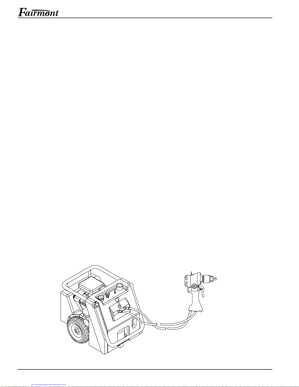
Reversible Drills
4455 Boeing Dr., Rockford, IL 61109-2988 815/397-7070
IMPORTANT SAFETY INFORMATION
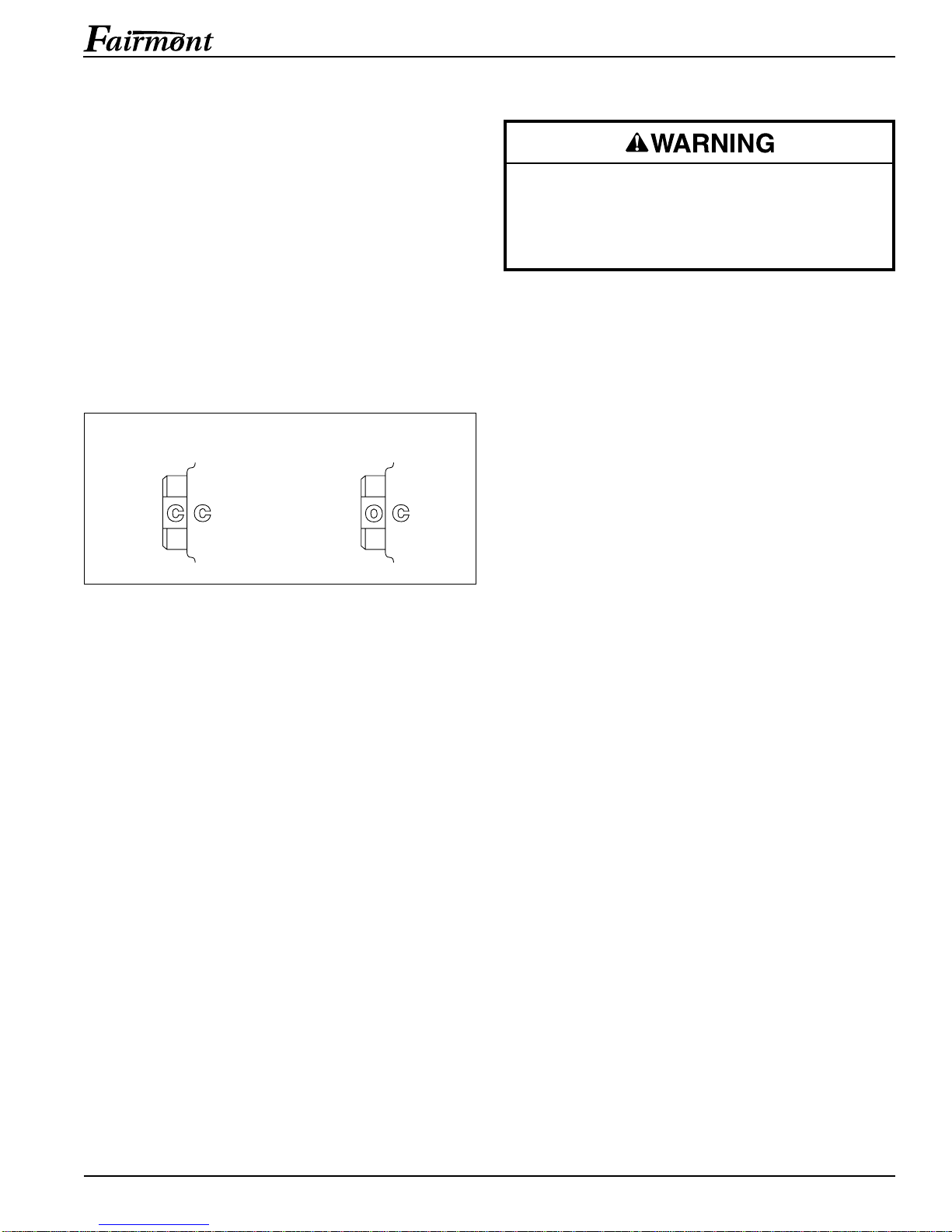
Do not reverse hydraulic flow. Operation with
hydraulic flow reversed can cause tool malfunc-
tion. Connect the pressure (supply) hose and tank
(return) hose to the proper tool ports.
Failure to observe this warning can result in
severe injury or death.
• Remove the chuck key from the chuck before
drilling. Operation with the key in the chuck can
result in severe injury.
• Inspect accessories before use. Discard acces-
sories that have cracks, chips or gouges.
• Keep all parts of the body away from rotating
parts when the tool is in operation. Contact with
moving parts can result in severe injury.
• Do not change accessories, inspect, adjust or
clean tool when it is connected to a power
source. Accidental start-up can result in serious
injury.
• Maintain a firm grip on tool, using both hands at
all times. Serious injury can result if the operator
does not control the tool.
• Do not lock the trigger in the power-ON position.
The operator cannot stop the tool when the
trigger is locked.
Failure to observe these warnings can result in
severe injury or death.
Tool and accessory may be hot
during and after operation. Allow to
cool before handling, or handle with
heat-resistant gloves.
Failure to observe this warning
could result in severe injury.
Do not exceed the maximum hydraulic flow, pres-
sure relief or back pressure listed in the Specifica-
tions and Parts manual.
Failure to observe this warning can result in severe
injury or death.
Do not disconnect tool, hoses or fittings while the
power source is running or if the hydraulic fluid is
hot. Hot hydraulic fluid can cause serious burns.
• Wear protective gloves when handling, remov-
ing and installing drill bits. Drill bits can cut even
when stationary.
• Inspect tool before use. Replace any worn,
damaged or missing parts with Fairmont re-
placement parts. An improperly assembled tool
can malfunction, injuring nearby personnel.
• Inspect the hydraulic hoses and couplings every
operating day. Repair or replace if leakage,
cracking, wear or damage is evident. Damaged
hoses or couplings can fail, resulting in injury or
property damage.
• Use this tool for the manufacturer’s intended
purpose only. Use other than that which is
described in this manual can result in injury or
property damage.
• Ensure that all bystanders are clear of the work
area when handling, starting, and operating the
tool. Nearby personnel can be injured by flying
debris or by flying parts in the event of a tool
malfunction.