Greenlee HID6506 User manual

Hydraulic
Rotary Impact Drill
Serial Code AML
OPERATION MANUAL
Read and understand all of the instructions and
safety information in this manual before operating
or servicing this tool.
Register this product at www.greenlee.com
Español............... 15
Français.............. 29
Deutsch .............. 43
Italiano................ 57
99940116 REV 2 © 2012 Greenlee Textron Inc. 2/12

Hydraulic Rotary Impact Drill
Greenlee / A Textron Company 4455 Boeing Dr. • Rockford, IL 61109-2988 USA • 815-397-7070
2
Table of Contents
Description .................................................................... 2
Safety ............................................................................ 2
Purpose of this Manual ................................................. 2
Other Publications......................................................... 2
Important Safety Information .....................................3–5
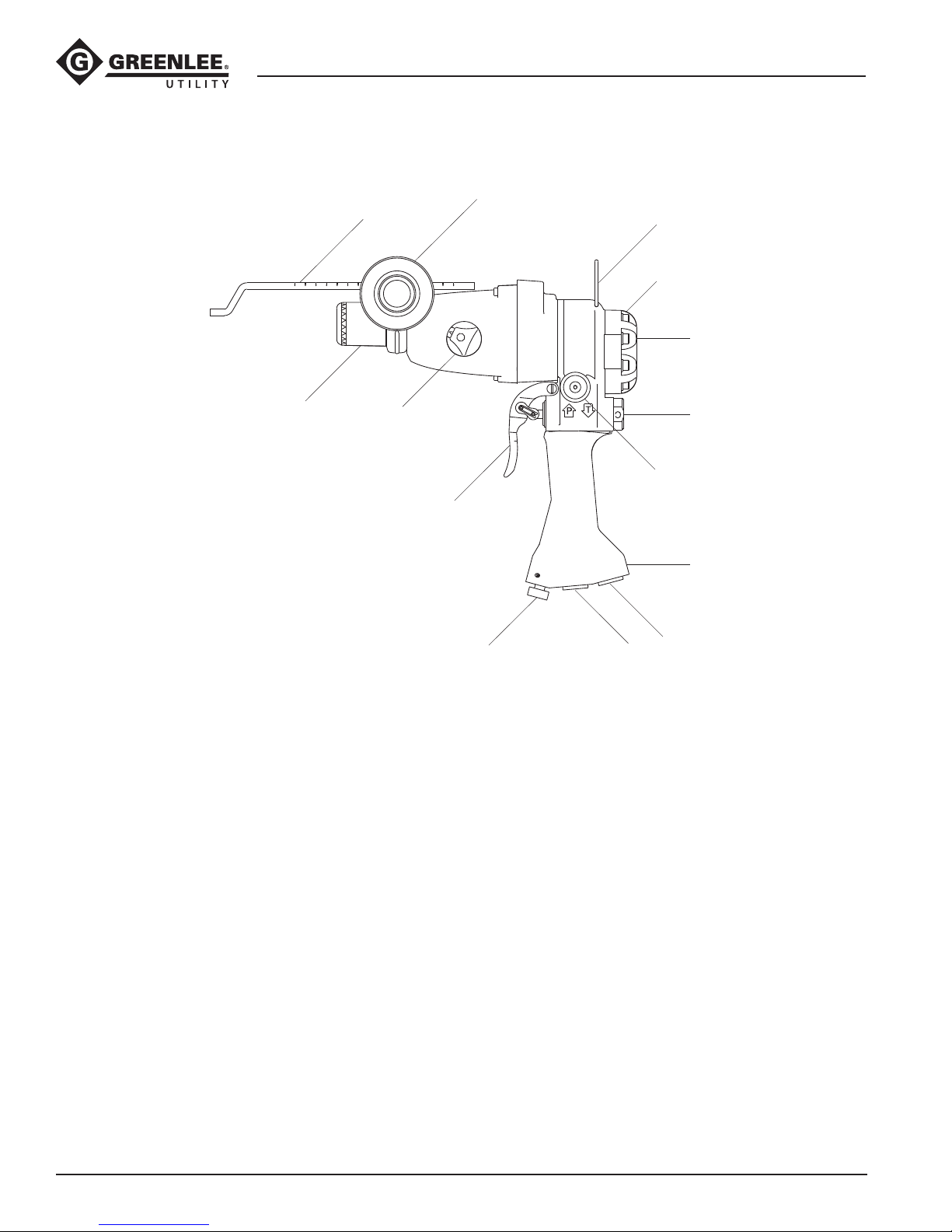
Identication.................................................................. 6
Specications................................................................ 7
Setting the Super Spool ................................................ 8
Setting the Tool to Drill or Hammer Drill........................ 8
Installing and Removing Drill Bits.................................. 9
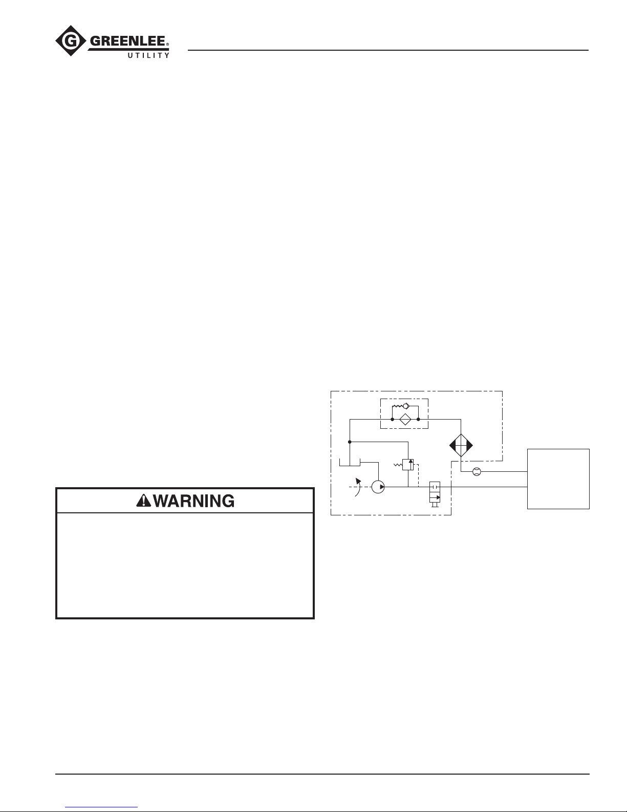
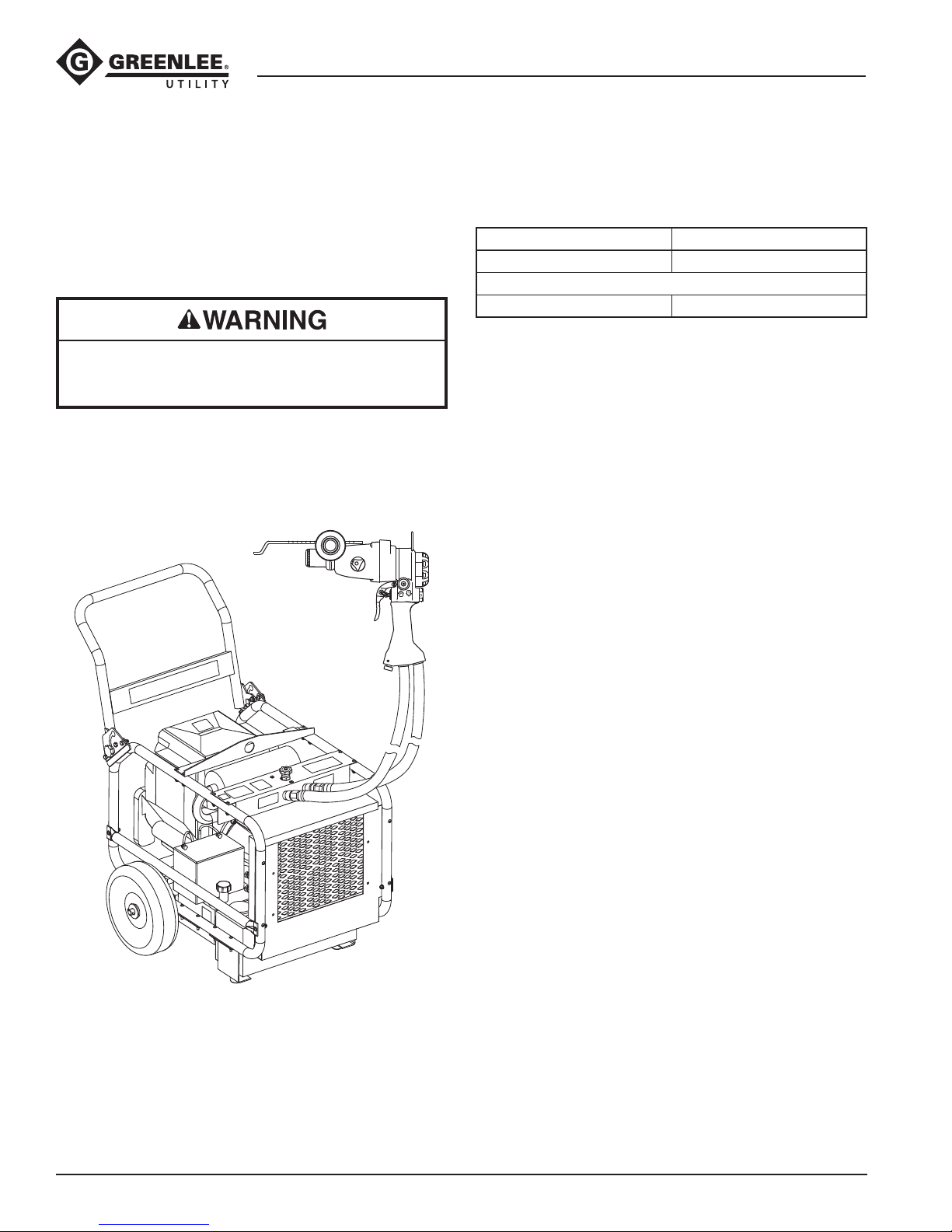
Hoses and Fittings ...................................................... 10
Typical Setup............................................................... 10
Hose Connections....................................................... 10
Operation..................................................................... 11
Maintenance................................................................ 12
Troubleshooting........................................................... 13
Español........................................................................ 15
Français....................................................................... 29
Deutsch ....................................................................... 43
Italiano......................................................................... 57
Description
The Greenlee Utility Hydraulic Rotary Impact Drill is
intended for use with impact-type bits for hammer
(impact) drilling in concrete, brick, rock and other
difcult-to-drill materials.
Features include a depth gauge, a directional spool for
forward or reverse operation, Super Spool™ for use
on either an Open-Center or Closed-Center hydraulic
system, and an insulated handle for operator comfort
and safety. A ow control cartridge, effective with
Serial Number 300, limits the hydraulic ow to 24.6 l/min
(6.5 gpm), allowing the tool to be connected to a
hydraulic system providing up to 45.4 l/min (12 gpm).
The tool also includes a variable torque output screw
and a built-in safety slip clutch to help prevent operator
injury if the drill bit catches.
Super Spool is protected by U.S. Patent No. 4548229.
KEEP THIS MANUAL
Safety
Safety is essential in the use and maintenance of
Greenlee Utility tools and equipment. This instruction
manual and any markings on the tool provide informa-
tion for avoiding hazards and unsafe practices related to
the use of this tool. Observe all of the safety information
provided.
Purpose of this Manual
This manual is intended to familiarize personnel with
the safe operation and maintenance procedures for the
following Greenlee Utility tool:
HID6506 (42309) Hydraulic Rotary Impact Drill
Serial Code AML
Keep this manual available to all personnel.
Replacement manuals are available upon request at no
charge at www.greenlee.com.
Other Publications
Tool Owners/Users
SAE Standard J1273 (Hose and Hose Assemblies):
Publication 99930323
Authorized Greenlee Utility Service Centers
Repair Manual: Publication 99915979
All specications are nominal and may change as design
improvements occur. Greenlee Textron Inc. shall not be liable for
damages resulting from misapplication or misuse of its products.
Super Spool is a trademark of Greenlee Textron Inc.

Hydraulic Rotary Impact Drill
Greenlee / A Textron Company 4455 Boeing Dr. • Rockford, IL 61109-2988 USA • 815-397-7070
3
IMPORTANT SAFETY INFORMATION
SAFETY
ALERT
SYMBOL
This symbol is used to call your attention to hazards
or unsafe practices which could result in an injury or
property damage. The signal word, dened below,
indicates the severity of the hazard. The message
after the signal word provides information for
preventing or avoiding the hazard.
Immediate hazards which, if not avoided, WILL result
in severe injury or death.
Hazards which, if not avoided, COULD result in
severe injury or death.
Hazards or unsafe practices which, if not avoided,
MAY result in injury or property damage.
Read and understand all of the
instructions and safety information
in this manual before operating or
servicing this tool.
Failure to observe this warning could
result in severe injury or death.
Wear eye protection when operating
or servicing this tool.
Failure to wear eye protection could
result in serious eye injury from ying
debris or hydraulic oil.
Wear hearing protection when using
this tool.
Failure to observe this warning could
result in serious injury.
Electric shock hazard:
This tool is not insulated. When
using this unit near energized electri-
cal lines:
• Use only certied non-conductive
hoses and proper personal protec-
tive equipment.
• Select and maintain the hydraulic
uid to meet the minimum dielec-
tric standards required by your
safety department.
Failure to observe this warning could
result in severe injury or death.
Skin injection hazard:
• Do not use ngers or hands to
check for leaks.
• Do not hold hose or couplers while
the hydraulic system is pressurized.
• Depressurize the hydraulic system
before servicing.
Oil under pressure easily punctures
skin causing serious injury, gangrene
or death. If you are injured by
escaping oil, seek medical attention
immediately.

Hydraulic Rotary Impact Drill
Greenlee / A Textron Company 4455 Boeing Dr. • Rockford, IL 61109-2988 USA • 815-397-7070
4
IMPORTANT SAFETY INFORMATION
• When using the tool in hammer drill mode, use
accessories that are approved for impact use
only. Accessories that are not approved for impact
applications can break when used in the hammer
drill mode.
• Inspect accessories before use. Discard accesso-
ries that have cracks, chips or gauges.
Failure to observe these warnings could result in
severe injury or death.
Some dust created by power sanding, sawing, grind-
ing, drilling, and other construction activities contains
chemicals known to the State of California to cause
cancer, birth defects or other reproductive harm.
Some examples of these chemicals are:
• Lead from lead-based paints
• Crystalline silica from bricks and cement and other
masonry products
• Arsenic and chromium from chemically-treated
lumber.
To reduce your exposure to these chemicals: work in
a well ventilated area, and work with approved safety
equipment, such as dust masks that are specially
designed to lter out microscopic particles.
• Remove the chuck key from the chuck before drill-
ing. Operation with the key in the chuck can result
in severe injury.
• Keep all parts of the body away from rotating parts
when the tool is in operation. Contact with moving
parts can result in severe injury.
• Do not change accessories, inspect or clean tool
when it is connected to a power source. Accidental
start-up can result in serious injury.
• Maintain a rm grip on tool, using both hands at all
times. Serious injury can result if an operator does
not control the tool.
• Do not lock trigger in the power-ON position.
Operator cannot stop tool when trigger is locked.
Failure to observe these warnings could result in
severe injury or death.
Tool and accessory may be hot
during and after operation.
Contact with hot surfaces could
result in serious injury.
Do not exceed the following hydraulic power source
maximums:
• Hydraulic ow: 45.4 l/min (12 gpm)
• Pressure relief setting: 138 bar (2000 psi)
• Back pressure: 13.8 bar (200 psi)
Failure to observe this warning could result in severe
injury or death.
Do not disconnect tool, hoses, or ttings while
the tool is running or if the hydraulic uid is
hot. Hot hydraulic uid can cause serious burns.
Do not reverse hydraulic ow. Operation with
hydrau-
lic ow reversed can cause tool malfunction.
Connect
the supply (pressure) hose and return (tank) hose to
the proper tool ports.
Failure to observe this warning could result in severe
injury or death.

Hydraulic Rotary Impact Drill
Greenlee / A Textron Company 4455 Boeing Dr. • Rockford, IL 61109-2988 USA • 815-397-7070
5
IMPORTANT SAFETY INFORMATION
• Wear protective gloves when handling, removing,
and installing drill bits. Drill bits can cut even when
stationary.
• Inspect tool before use. Replace any worn
or damaged parts. A damaged or improperly
assembled tool can malfunction, injuring nearby
personnel.
• Inspect the hydraulic hoses and couplings every
operating day. Repair or replace if leakage, crack-
ing, wear, or damage is evident. Damaged hoses
or couplings can fail, resulting in injury or property
damage.
• Use this tool for manufacturer’s intended use only.
Use other than that which is described in this
manual could result in injury or property damage.
• Make sure all bystanders are clear of the work area
when handling, starting, and operating the tool.
Nearby personnel can be injured by ying parts in
the event of a tool malfunction.
Prolonged exposure to vibration or very repetitive
hand and arm movements may cause injury. Stop
using any tool if discomfort, tingling feeling, or pain
occurs. Consult a physician before resuming use of
the tool.
Procedure for disconnecting hydraulic hoses, ttings
or components:
1. Move the ow lever on the hydraulic power
source to the OFF position.
2. Stop the power source.
3. Follow the sequence under Disconnecting Hoses
to prevent pressure buildup. In case some
pressure has built up, loosen hoses, ttings, or
components slowly.
Emergency stop procedure:
1. Release the trigger.
2. Shut off the hydraulic power source.
Note: Keep decals clean and legible. Replace decals
when necessary—see the decals listed in the Service
manual.

Hydraulic Rotary Impact Drill
Greenlee / A Textron Company 4455 Boeing Dr. • Rockford, IL 61109-2988 USA • 815-397-7070
6
Identification
8
9
11
12
13
14
1
2
3
4
5
6
7
10
1. Trigger
2. Drill/Hammer Drill Selector Knob
3. Collar
4. Depth Gauge
5. Auxiliary Handle
6. Lifting Hook
7. Motor Cap
Hydraulic Rotary Impact Drill
8. Serial Number
9. Super Spool
10. Directional Spool
11. Handle
12. Tank Port
13. Pressure Port
14. Variable Torque Output Screw

Hydraulic Rotary Impact Drill
Greenlee / A Textron Company 4455 Boeing Dr. • Rockford, IL 61109-2988 USA • 815-397-7070
7
Hydraulic Rotary Impact Drill
Type of Hydraulic System ....................... Open-Center or
Closed-Center
Hydraulic Pressure Port.............3/4–16 SAE O-ring Boss
Hydraulic Tank Port ...................3/4–16 SAE O-ring Boss
Bits
SDS Plus Type Chuck ................ SDS Plus Type Shank
Noise Levels
Sound Power Level (maximum) ..........................85 LWA
Mass/Weight................................................ 4.1 kg (9 lbs)
Length ..................................................... 285 mm (11.2")
Width ........................................................... 89 mm (3.5")
Height...................................................... 280 mm (11.0")
Output
Revolutions per Minute @ 18.9 l/min (5 gpm) .........900
Revolutions per Minute @ 22.7 l/min (6 gpm) .......1050
Impacts per Minute @ 22.7 l/min (6 gpm) .............5400
Max. Single Impact Energy ...................................2.4 J
Drilling Capacity
Concrete................................................... 22 mm (7/8")
Steel ......................................................... 13 mm (1/2")
Wood.....................................................30 mm (1-1/8")
Core Bit .................................................68 mm (2-5/8")
Hydraulic Power Source
Do not exceed the following hydraulic power source
maximums:
• Hydraulic ow: 45.4 l/min (12 gpm)
• Pressure relief setting: 138 bar (2000 psi)
• Back pressure: 13.8 bar (200 psi)
Failure to observe this warning could result in severe
injury or death.
Type of Hydraulic System........................ Open-Center or
Closed-Center
Flow
Minimum ..........................................15.1 l/min (4 gpm)
Recommended.................................22.7 l/min (6 gpm)
Maximum .......................................45.4 l/min (12 gpm)
Pressure Relief Setting
Minimum ......................................... 68.9 bar (1000 psi)
Maximum ......................................... 138 bar (2000 psi)
Filtration............................................ 10 micron (nominal)
Back Pressure (maximum)* .................. 13.8 bar (200 psi)
* 13.8 bar (200 psi) is the maximum agreed standard back pressure
for the HTMA (Hydraulic Tool Manufacturers Association).
Greenlee Utility tool will operate satisfactorily at this standard.
1. Maximum hydraulic uid temperature must not
exceed 60 °C (140 °F). A sufcient oil cooling
capacity is needed to limit the hydraulic uid
temperature.
2. Hydraulic ow must not exceed 45.4 l/min (12 gpm).
Install a ow meter in the return line to measure the
rate of hydraulic ow before using the tool.
3. Pressure relief valve setting must not exceed
138bar (2000 psi) at your tool’s maximum ow.
Locate the pressure relief valve in the supply circuit
to limit excessive hydraulic pressure to the tool.
Hydraulic Schematic
FILTER
(10 MICRON)
COOLER
RELIEF
VALVE
138 bar
(2000 psi)
CONTROL
VALVE FLOW METER
T
PTOOL
RESERVOIR
PUMP
POWER SOURCE
Recommended Hydraulic Fluids
Use any non-detergent, petroleum-based hydraulic
uid which meets the following specications or HTMA
specications.
S.U.S. @:
38 °C (100 °F)...............................................140 to 225
99 °C (210 °F)............................................ 40 minimum
Flash Point................................170 °C (340 °F) minimum
Pour Point..................................-34 °C (-30 °F) minimum
Specifications

Hydraulic Rotary Impact Drill
Greenlee / A Textron Company 4455 Boeing Dr. • Rockford, IL 61109-2988 USA • 815-397-7070
8
Setting the Super Spool
The Super Spool allows the tool to be used with either
Open-Center or Closed-Center hydraulic systems.
Open-Center Hydraulic System
Use a wrench to turn the Super Spool until the letter “O”
on the spool is aligned with the letter “C” on the tool
handle.
Closed-Center Hydraulic System
Use a wrench to turn the Super Spool until the letter “C”
on the spool is aligned with the letter “C” on the tool
handle.
Setting the Tool to Drill
or Hammer Drill
The drill/hammer drill selector knob allows the tool to
be used for either standard drilling or hammer (impact)
drilling. Depress the red indication arrow (1) to turn the
selector knob.
23
1
Set the knob so that the red arrow icon (1) points to the
desired operation:
• Drill bit icon (2) for standard drilling
• Hammer icon (3) for hammer drilling
Setting the Super Spool
Closed-Center Open-Center

Hydraulic Rotary Impact Drill
Greenlee / A Textron Company 4455 Boeing Dr. • Rockford, IL 61109-2988 USA • 815-397-7070
9
Installing and Removing Drill Bits
Greenlee Utility recommends using Greenlee impact-
style bits. See Accessories in this manual.
• When using the tool in hammer drill mode, use
accessories that are approved for impact use
only. Accessories that are not approved for impact
applications can break when used in the hammer
drill mode.
• Inspect accessories before use. Discard accesso-
ries that have cracks, chips or gauges.
Failure to observe these warnings could result in
severe injury or death.
Some bits may whip or bend under sideload.
• Do not use bits with a long spiral and center
support.
• When using an impact bit, run the power source
at the minimum ow. Refer to the “Specications”
section.
Failure to observe this warning could result in severe
injury or death.
Long SpiralCenter Support
x
SDS Plus Type Chuck
1. Inspect the chuck. Remove any dirt or other
contamination.
2. Select an SDS Plus type of bit. Align the long slots
in the shank of the bit with the index mark in the
dust cover on the end of the collar. Insert the bit into
the chuck.
3. Check to make sure the collar is securely holding
the bit.
4. To remove the drill bit, twist the collar so that it
releases the bit.

Hydraulic Rotary Impact Drill
Greenlee / A Textron Company 4455 Boeing Dr. • Rockford, IL 61109-2988 USA • 815-397-7070
10
Hose Connections
Tool Port Identification
One of three methods is used to identify the pressure
and tank ports of Greenlee Utility tools. Match the mark-
ings on your tool to this table.
Pressure Port Tank Port
P T
or
In Out
Connecting Hoses
1. Move the ow lever on the hydraulic power source
to the OFF position.
2. Stop the hydraulic power source.
3. Connect the tank hose to the tank port on the
power source, and then to the tank port on the tool.
4.
Connect the pressure hose to the pressure port on
the tool, and then to the pressure port on the power
source.
Disconnecting Hoses
1. Move the ow lever on the hydraulic power source
to the OFF position.
2. Stop the hydraulic power source.
3. Disconnect the pressure hose from the power
source, and then from the tool.
4. Disconnect the tank hose from the tool, and then
from the power source.
5. Install dust caps over the ports to prevent
contamination.
Hoses and Fittings
Installation and Maintenance
See publication 99930323, SAE Standard J1273
(Hoseand Hose Assemblies).
Replacement
See a Greenlee Utility catalog or Greenlee Utility
publication 99910322, Low Pressure Quick Couplers,
Adapters and Hoses.
Do not disconnect tool, hoses, or ttings while
the power source is running or if the hydraulic uid is
hot. Hot hydraulic uid could cause serious burns.
Typical Setup

Hydraulic Rotary Impact Drill
Greenlee / A Textron Company 4455 Boeing Dr. • Rockford, IL 61109-2988 USA • 815-397-7070
11
Operation
Wear eye protection when operating
or servicing this tool.
Failure to wear eye protection could
result in serious eye injury from ying
debris or hydraulic oil.
Electric shock hazard:
This tool is not insulated. When
using this unit near energized electri-
cal lines:
• Use only certied non-conductive
hoses and proper personal protec-
tive equipment.
• Select and maintain the hydraulic
uid to meet the minimum dielec-
tric standards required by your
safety department.
Failure to observe this warning could
result in severe injury or death.
Skin injection hazard:
• Do not use ngers or hands to
check for leaks.
• Do not hold hose or couplers while
the hydraulic system is pressurized.
• Depressurize the hydraulic system
before servicing.
Oil under pressure easily punctures
skin causing serious injury, gangrene
or death. If you are injured by
escaping oil, seek medical attention
immediately.
• When using the tool in hammer drill mode, use
accessories that are approved for impact use
only. Accessories that are not approved for impact
applications can break when used in the hammer
drill mode.
• Inspect accessories before use. Discard accesso-
ries that have cracks, chips or gauges.
Failure to observe these warnings could result in
severe injury or death.
1. Stop the hydraulic power source.
2. Set the Super Spool, select the drill or hammer drill
operating mode, and install a bit as described
in the previous sections of this manual. Set the
directional spool to the appropriate position
(forward or reverse).
3. Connect the tool to the power source according to
the instructions under Hose Connections.
• Do not operate the tool with the Drill/Hammer Drill
selector knob in a position between drilling and
hammer drilling.
• Allow the tool to stop before changing the position
of the drill/hammer drill selector knob.
• Do not change the position of the directional spool
while the tool is operating. Allow the tool to stop
before changing direction.
4. Start the power source.
5. Grasp the trigger handle with one hand, and grasp
the auxiliary handle with your other hand. This will
allow you to apply leverage while operating the tool.
6. To start the tool, squeeze the trigger.
Note: Use the variable torque adjustment screw
to achieve the necessary amount of torque. Turn
the screw counterclockwise to increase torque, or
clockwise to decrease torque.
7. To stop the tool, release the trigger.
8. When the tool is not in use, stop the power source
to reduce heat and wear on the tool.

Hydraulic Rotary Impact Drill
Greenlee / A Textron Company 4455 Boeing Dr. • Rockford, IL 61109-2988 USA • 815-397-7070
12
Maintenance
Do not change accessories, inspect or clean tool or
accessories when it is connected to a power source.
Accidental start-up can result in serious injury.
Failure to observe this warning could result in severe
injury or death.
Wear eye protection when operating
or servicing this tool.
Failure to wear eye protection could
result in serious eye injury from ying
debris or hydraulic oil.
Use this maintenance schedule to maximize the tool’s
service life.
Notes: Keep all decals clean and legible. Replace
decals when necessary. Refer to the Service manual for
decal part numbers.
When disposing of any components (hydraulic hoses,
hydraulic fluid, worn parts, etc.), do so in accordance
with federal, state, and local laws or ordinances.
Daily
1. Wipe all tool surfaces clean.
2.
Inspect the hydraulic hoses and ttings for signs of
leaks, cracks, wear or damage. Replace if necessary.
3. Install dust caps over the hydraulic ports when the
tool is disconnected.
Monthly
Perform a thorough inspection of the hydraulic hoses
and ttings as described in publication 99930323,
SAE J1273 (Hose and Hose Assemblies).
Annually
If required by your organization’s regulations, have the
tool inspected by an authorized Greenlee Utility service
center.

Hydraulic Rotary Impact Drill
Greenlee / A Textron Company 4455 Boeing Dr. • Rockford, IL 61109-2988 USA • 815-397-7070
13
Problem Probable Cause Probable Remedy
Tool does not operate. Improper power source. Refer to the “Specications” section.
Verify that the power source meets the
specications.
Hydraulic uid level low. Check the uid level. Check system for leaks.
Incorrect hydraulic uid viscosity. Refer to “Recommended Hydraulic Fluids” in
the “Specications” section.
Hose connections at tool reversed. Depressurize hydraulic system. Switch the
hose connections.
Variable torque adjustment screw
turned too far clockwise, completely
stopping the ow of hydraulic uid.
Turn the variable torque adjustment screw
counterclockwise to achieve the necessary
amount of torque.
Tool operates slowly or
erratically.
Hydraulic uid cold. Allow uid to warm to the operating tempera-
ture. Actuate the tool intermittently to reduce
the warming time.
Power source not adjusted correctly. Refer to the power source operator’s manual
for setting the ow and pressure. Set the ow
and pressure to correspond with the tool.
Air in the hydraulic system. See power source manufacturer’s instructions
for removing air from the system.
Incorrect hydraulic uid viscosity. Refer to “Recommended Hydraulic Fluids” in
the “Specications” section.
Tool feels hot. Hydraulic uid level low. Check the uid level. Check system for leaks.
Incorrect hydraulic uid viscosity. Refer to “Recommended Hydraulic Fluids” in
the “Specications” section.
Hydraulic uid dirty. Drain reservoir; ush and ll with clean uid.
Change lter.
Before troubleshooting, determine whether the problem
is in the tool, the hoses, or the power source. Substitute
a tool, hoses, or power source known to be in good
working order to eliminate the item that is not operating.
If the problem is in the tool, see the troubleshoot-
ing table in this manual. If the problem is in the power
source, see the troubleshooting section of the power
source instruction manual.
Troubleshooting

4455 Boeing Drive • Rockford, IL 61109-2988 • USA • 815-397-7070
An ISO 9001 Company • Greenlee Textron Inc. is a subsidiary of Textron Inc.
USA Tel: 800-435-0786
Fax: 800-451-2632
Canada Tel: 800-435-0786
Fax: 800-524-2853
International Tel: +1-815-397-7070
Fax: +1-815-397-9247
www.greenlee.com

Taladro de Percusión
Rotatorio Hidráulico
Código de serie AML
MANUAL DE OPERACIÓN
Lea y entienda todas las instrucciones y la
información sobre seguridad que aparecen en
este manual, antes de manejar esta herramienta o
darle mantenimiento.
Registre este producto en www.greenlee.com
99940116 REV 2 © 2012 Greenlee Textron Inc. 2/12

Taladro de Percusión Rotatorio Hidráulico
Greenlee / A Textron Company 4455 Boeing Dr. • Rockford, IL 61109-2988 USA • 815-397-7070
16
Índice
Descripción ................................................................. 16
Acerca de la seguridad................................................ 16
Propósito de este manual ........................................... 16
Otras publicaciones .................................................... 16
Importante Información sobre Seguridad ..............17–19
Identicación ............................................................... 20
Especicaciones ......................................................... 21
Montaje del Super Spool............................................. 22
Montaje de la herramienta al taladro
o al taladro de martillo................................................. 22
Instalación y remoción de las brocas para taladro...... 23
Mangueras y accesorios ............................................. 24
Modelo de instalación ................................................. 24
Conexión de las mangueras........................................ 24
Operación.................................................................... 25
Mantenimiento............................................................. 26
Diagnóstico y solución de fallas.................................. 27
Descripción
El Taladro de Percusión Rotatorio Hidráulico de
Greenlee Utility ha sido diseñado a n de utilizarse
con brocas de percusión para perforar con fuerza de
impacto hormigón, ladrillo, roca y otros materiales
difíciles detaladrar.
Entre las características se cuentan un calibre
de profundidad, una bobina direccional para
funcionamiento hacia adelante y en reversa, Super
Spool™ para uso en sistemas hidráulicos de circuito
abierto o cerrado, y una empuñadura aislada para
brindarle comodidad y seguridad al operador. Un
cartucho para control de gasto, comenzando con el
Número de Serie 300, limita el gasto hidráulico a
24,6l/min (6,5 gpm), permitiendo que la herramienta se
conecte a un sistema hidráulico que proporcione hasta
45,4 l/min (12 gpm). La herramienta incluye además
un tornillo de salida de par de torsión variable y un
embrague deslizante de seguridad para ayudar a evitar
que el operador se lesione si la broca para taladro se
atasca.
Super Spool está protegido por la patente
estadounidense No. 4548229.
CONSERVE ESTE MANUAL
Acerca de la seguridad
Es fundamental observar métodos seguros al utilizar y
dar mantenimiento a las herramientas y equipo Greenlee
Utility. Este manual de instrucciones y todas las marcas
que ostenta la herramienta le ofrecen la información
necesaria para evitar riesgos y hábitos poco seguros
relacionados con su uso. Siga toda la información sobre
seguridad que se proporciona.
Propósito de este manual
Este manual tiene como propósito familiarizar al
personal con los procedimientos de operación y
mantenimiento seguros para la siguiente herramienta
Greenlee Utility:
Taladro de Percusión Rotatorio Hidráulico
HID6506 (42309)
Código de serie AML
Mantenga siempre este manual al alcance de todo el
personal.
Puede obtener copias adicionales de manera gratuita,
previa solicitud en www.greenlee.com.
Otras publicaciones
Para propietarios o usuarios
Norma SAE J1273 (Manguera y conjuntos de
mangueras): Publicación 99930323
Centros de Servicio Autorizado Greenlee Utility
Manual de reparación: Publicación 99915979
Todas las especicaciones son nominales y pueden cambiar conforme
tengan lugar mejoras de diseño. Greenlee Textron Inc. no se hace
responsable de los daños que puedan surgir de la mala aplicación o
mal uso de sus productos.
Super Spool es una marca registrada de Greenlee Textron Inc.

Taladro de Percusión Rotatorio Hidráulico
Greenlee / A Textron Company 4455 Boeing Dr. • Rockford, IL 61109-2988 USA • 815-397-7070
17
IMPORTANTE INFORMACIÓN SOBRE SEGURIDAD
SÍMBOLO
DE ALERTA
SOBRE
SEGURIDAD
Este símbolo se utiliza para indicar un riesgo o
práctica poco segura que podría ocasionar lesiones
o daños materiales. Cada uno de los siguientes
términos denota la gravedad del riesgo. El mensaje
que sigue a dichos términos le indica cómo puede
evitar o prevenir ese riesgo.
Peligros inmediatos que, de no evitarse,
OCASIONARÁN graves lesiones o incluso la muerte.
Peligros que, de no evitarse, PODRÍAN
OCASIONAR graves lesiones o incluso la muerte.
Peligro o prácticas peligrosas que, de no evitarse,
PUEDEN OCASIONAR lesiones o daños materiales.
Lea y entienda todas las
instrucciones y la información sobre
seguridad que aparecen en este
manual, antes de manejar esta
herramienta o darle mantenimiento.
De no observarse esta advertencia
pueden sufrirse graves lesiones o
incluso la muerte.
Utilice protectores para ojos al
manejar o darle mantenimiento a
esta herramienta.
De no utilizar protectores para ojos
puede sufrir graves lesiones oculares
ocasionadas si el aceite para
aparatos hidráulicos, o restos de
materiales llegaran a saltar.
Al manejar esta herramienta utilice
protección auditiva.
De no observarse esta advertencia
podrían sufrirse lesiones graves.
Peligro de electrocución:
Esta herramienta no está aislada. Al
utilizar esta unidad cerca de líneas
eléctricas energizadas:
• Utilice únicamente mangueras no
conductivas aprobadas y equipo de
protección personal adecuado.
• Seleccione siempre un líquido
para aparatos hidráulicos, que
cumpla con los estándares
dieléctricos mínimos exigidos por
su departamento de seguridad, y
manténgalo al nivel adecuado.
De no observarse esta advertencia
pueden sufrirse graves lesiones o
incluso la muerte.
Peligro de inyección cutánea:
• No use los dedos ni las manos para
localizar fugas.
• No toque la manguera ni los
acopladores mientras el sistema
hidráulico se encuentre presurizado.
• Purgue la presión en el sistema
hidráulico antes de darle
mantenimiento.
El aceite bajo presión punza la
piel fácilmente provocando graves
lesiones, gangrena o la muerte. Si se
lesiona debido a una fuga de aceite,
solicite atención médica de inmediato.

Taladro de Percusión Rotatorio Hidráulico
Greenlee / A Textron Company 4455 Boeing Dr. • Rockford, IL 61109-2988 USA • 815-397-7070
18
IMPORTANTE INFORMACIÓN SOBRE SEGURIDAD
• Cuando opere la herramienta en el modo de
taladro de martillo, utilice únicamente accesorios
aprobados para aplicaciones donde sea necesaria
la fuerza por percusión. Los accesorios que no han
sido aprobados para este tipo de aplicaciones se
pueden quebrar al utilizarse en el modo de taladro
de martillo.
• Revise minuciosamente los accesorios antes de
utilizarlos. Deseche aquéllos que presenten grietas,
mellas o desportilladuras.
De no observarse estas advertencias pueden sufrirse
graves lesiones o incluso la muerte.
Algunos polvos generados por el lijado, aserrado,
amolado, taladrado con herramienta eléctrica y otras
actividades de construcción contienen sustancias
químicas que el Estado de California conoce como
causantes de cáncer, defectos congénitos u otros
daños al sistema reproductor. Algunos ejemplos de
estos químicos son los siguientes:
• Plomo de las pinturas con base de plomo
• Sílice cristalina de los ladrillos y cementos, y de
otros productos de mampostería
• Arsénico y cromo de la madera tratada
químicamente.
A n de reducir su exposición a estas sustancias
químicas: trabaje en un área bien ventilada, y
trabaje con equipo de seguridad apropiado, tal
como mascarillas contra polvo que están diseñadas
especialmente para ltrar partículas microscópicas.
• Retire del portabrocas la llave del portabrocas
antes de perforar. Hacer funcionar la herramienta
con la llave en el portabrocas puede ocasionar
graves lesiones.
• Mantenga todas las partes del cuerpo alejadas de
las piezas giratorias siempre que la herramienta
esté en funcionamiento. El contacto con las piezas
en movimiento puede ocasionar graves lesiones.
• No cambie accesorios ni inspeccione o limpie la
herramienta mientras esté conectada a una fuente
de potencia. Si ésta se activa accidentalmente,
podría ocasionar graves lesiones.
• Siempre sostenga la herramienta rmemente con
ambas manos. Si pierde el control de la unidad
podría ocasionar graves lesiones.
• No trabe el gatillo en la posición “ON”. El operador
no podrá detener la herramienta si se encuentra
trabada en dicha posición.
De no observarse estas advertencias pueden sufrirse
graves lesiones o incluso la muerte.
Tanto la herramienta como los
accesorios pueden alcanzar
temperaturas sumamente altas
mientras están en operación o
incluso una vez que han sido
apagados.
El contacto con supercies calientes
puede producir lesiones graves.
No exceda los máximos a continuación para la
fuente de potencia hidráulica:
• Gasto hidráulico: 45,4 l/min
• Ajuste de la presión de seguridad: 138 bar
• Contrapresión: 13,8 bar
De no observarse esta advertencia podrían sufrirse
graves lesiones o incluso la muerte.

Taladro de Percusión Rotatorio Hidráulico
Greenlee / A Textron Company 4455 Boeing Dr. • Rockford, IL 61109-2988 USA • 815-397-7070
19
IMPORTANTE INFORMACIÓN SOBRE SEGURIDAD
No desconecte la herramienta, ni las mangueras o
accesorios mientras la unidad esté encendida o el
líquido hidráulico esté caliente. El líquido hidráulico
caliente puede ocasionar quemaduras graves.
No invierta el gasto hidráulico. Operar la herramienta
con el gasto invertido ocasionará un funcionamiento
inadecuado.HORIZONTAL 100> Conecte las
mangueras de suministro (presión) y la de retorno
(tanque), en los oricios correspondientes en la
herramienta.
De no observarse esta advertencia pueden sufrirse
graves lesiones o incluso la muerte.
• Utilice guantes protectores al manipular, retirar
o colocar las brocas para taladro; éstas pueden
cortar incluso cuando no están en movimiento.
• Revise la herramienta antes de utilizarla.
Reemplace cualquier pieza desgastada o dañada.
Una herramienta dañada o montada de manera
incorrecta tendrá un funcionamiento errático y
puede lesionar al personal que se encuentre en el
área.
• Revise minuciosamente las mangueras hidráulicas
y los acoplamientos cada vez que vaya a utilizar la
herramienta. Repárelos o reemplácelos si presentan
fugas, grietas, desgaste o daños evidentes. Las
mangueras y acoplamientos averiados pueden fallar
y ocasionar lesiones o daños materiales.
• Utilice la herramienta únicamente para el uso
para el que ha sido diseñada por el fabricante. Si
se utiliza de una manera distinta a la descrita en
este manual puede ocasionarse lesiones o daños
materiales.
• Asegúrese de que no haya circunstantes en
el área de trabajo al manipular la herramienta,
ponerla en funcionamiento o manejarla, El personal
del área podría sufrir lesiones si alguna pieza
saliera disparada al haber un desperfecto de la
herramienta.
La exposición prolongada a la vibración o
movimientos muy repetidos de manos y brazos
puede causar lesiones. Detenga el uso de cualquier
herramienta si siente incomodidad, hormigueo o
dolor. Consulte a un médico antes de reanudar el uso
de la herramienta.
Procedimiento para desconectar las mangueras,
accesorios o demás componentes hidráulicos:
1. Coloque la palanca de gasto –ubicada en la
fuente de potencia hidráulica– en la posición de
apagado (OFF).
2. Apague la fuente de potencia.
3. Siga la secuencia detallada en “Desconexión de
las mangueras” a n de evitar la acumulación
de presión. En caso de que esto ocurra, aoje
lentamente las mangueras, los accesorios o los
componentes.
Procedimiento de apagado de emergencia:
1. Suelte el gatillo.
2. Apague la fuente de potencia hidráulica.
Nota: Mantenga las etiquetas de advertencia limpias y
legibles. Reemplace las etiquetas según sea necesario.
Véase la lista de etiquetas en el Manual de reparación.

Taladro de Percusión Rotatorio Hidráulico
Greenlee / A Textron Company 4455 Boeing Dr. • Rockford, IL 61109-2988 USA • 815-397-7070
20
Identificación
1. Gatillo
2. Perilla de Selección de Taladro/
Taladro de Martillo
3. Collarín
4. Calibre de Profundidad
5. Empuñadura Auxiliar
6. Gancho de Izar
7. Tapa del Motor
Taladro de Percusión Rotatorio Hidráulico
8. Número de Serie
9. Super Spool
10. Carrete Direccional
11. Empuñadura
12. Oricio del Tanque
13. Oricio de Presión
14. Tornillo de Salida de Par de
Torsión Variable
8
9
11
12
13
14
1
2
3
4
5
6
7
10
Other manuals for HID6506
1
Table of contents
Languages:
Other Greenlee Drill manuals
Popular Drill manuals by other brands

MasterForce
MasterForce 241-0412 Operator's manual

BLACK DECKER
BLACK DECKER BDCDD12 Original instructions

Black & Decker
Black & Decker BDED200C instruction manual

Hitachi Koki
Hitachi Koki DV 20VB2 Handling instructions

Power Craft
Power Craft 4500 instruction manual

Hilti
Hilti UH 650 operating instructions