GreenWorks DDG301 User manual

DDG301
EN OPERATOR MANUAL
FR MANUEL D’OPÉRATEUR
DRILL DRIVER
PERCEUSE À PERCUSSION À BALAIS
ES MANUAL DEL OPERADORTALADRO DE IMPACTO CON ESCOBILLAS
CD24B00

1 Description.................................... 4
1.1 Purpose...................................................... 4
1.2 Overview.................................................... 4
2 General power tool safety
warnings........................................ 4
2.1 Work area safety........................................ 4
2.2 Electrical safety.......................................... 4
2.3 Personal safety...........................................4
2.4 Power tool use and care.............................4
2.5 Battery tool use and care........................... 5
2.6 Service....................................................... 5
2.7 Specific safety rules................................... 5
3 Proposition 65............................... 6
4 Symbols on the product.................6
5 Risk levels..................................... 6
6 Installation..................................... 6
6.1 Unpack the machine...................................6
6.2 Install the battery pack............................... 7
6.3 Remove the battery pack........................... 7
6.4 Install the bit............................................... 7
6.5 Remove the bit........................................... 7
7 Operation.......................................7
7.1 Start the machine....................................... 7
7.2 Stop the machine....................................... 7
7.3 Adjust the variable speed........................... 7
7.4 Adjust the two-speed gear train..................7
7.5 Adjust the reversing button.........................8
7.6 Drill materials..............................................8
8 Maintenance..................................8
8.1 Remove the chuck......................................8
8.2 Retighten a loose chuck............................. 9
8.3 Clean the machine..................................... 9
9 Technical data............................... 9
10 Limited warranty............................ 9
11 Exploded view............................. 10
3
English EN

1 DESCRIPTION
1.1 PURPOSE
The machine is intended for driving in and loosening
screws and bolts as well as for tightening and loosening
nuts within the respective range of dimension.
1.2 OVERVIEW
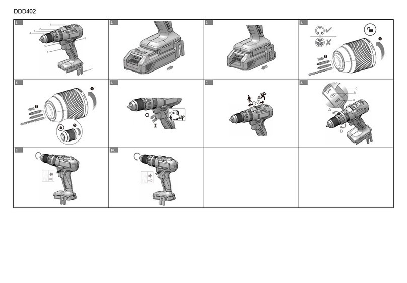
Figure 1.
1Two-speed gear
train ( HI-LO)
2Torque adjustment
ring
3Keyless chuck
4Switch trigger
5LED work light
6Reversing button
7Bit storage
2 GENERAL POWER TOOL
SAFETY WARNINGS
WARNING
Read all safety warnings and all instructions. Failure to
follow the warnings and instructions may result in
electric shock, fire and/or serious injury.
Save all warnings and instructions for future reference.
The term “power tool” in the warnings refers to your
battery-operated (cordless) power tool.
2.1 WORK AREA SAFETY
•Keep work area clean and well lit.
Cluttered or dark
areas invite accidents.
•Do not operate power tools in explosive
atmospheres, such as in the presence of flammable
liquids, gases or dust.
Power tools create sparks
which may ignite the dust or fumes.
•Keep children and bystanders away while operating
a power tool.
Distractions can cause you to lose
control.
2.2 ELECTRICAL SAFETY
•Power tool plugs must match the outlet. Never
modify the plug in any way. Do not use any adapter
plugs with earthed (grounded) power tools.
Unmodified plugs and matching outlets will reduce
risk of electric shock.
•Avoid body contact with earthed or grounded
surfaces, such as pipes, radiators, ranges and
refrigerators.
There is an increased risk of electric
shock if your body is earthed or grounded.
•Do not expose power tools to rain or wet conditions.
Water entering a power tool will increase the risk of
electric shock.
•Do not abuse the cord. Never use the cord for
carrying, pulling or unplugging the power tool. Keep
cord away from heat, oil, sharp edges and moving
parts.
Damaged or entangled cords increase the risk
of electric shock.
•When operating a power tool outdoors, use an
extension cord suitable for outdoor use.
Use of a
cord suitable for outdoor use reduces the risk of
electric shock.
•If operating a power tool in a damp location is
unavoidable, use a residual current device (RCD)
protected supply.
Use of an RCD reduces the risk of
electric shock.
2.3 PERSONAL SAFETY
•Stay alert, watch what you are doing and use
common sense when operating a power tool. Do not
use a power tool while you are tired or under the
influence of drugs, alcohol or medication.
A lapse of
attention while operating power tools may result in
serious personal injury.
•Use personal protection. Always wear eye
protection.
Protective products such as dust mask,
non-skid safety shoes, hard hat or hearing
protection used appropriately will reduce personal
injuries.
•Prevent unintentional starting. Ensure the switch is
in the off position before connecting to power source
and/or battery pack and when picking up or carrying
the tool.
Carrying power tools with your finger on the
switch or energizing power tools that have the
switch on invites accidents.
•Remove any adjusting key or wrench before turning
the power tool on.
A wrench or a key left attached to
a rotating part of the power tool may result in
personal injury.
•Do not over-reach. Keep proper footing and balance
at all times.
This enables better control of the power
tool in unexpected situations.
•Dress properly. Do not wear loose clothing or
jewellery. Keep your hair, clothing and gloves away
from moving parts.
Loose clothes, jewellery or long
hair can be caught in moving parts.
•If devices are provided for the connection of dust
extraction and collection facilities, ensure these are
connected and properly used.
Use of dust collection
can reduce dust related hazards.
2.4 POWER TOOL USE AND CARE
•Do not force the power tool. Use the correct power
tool for your application.
The correct power tool will
do the job better and safer at the rate for which it
was designed.
•Do not use the power tool if the switch does not turn
it on and off.
Any power tool that cannot be
controlled with the switch is dangerous and must be
repaired.
•Disconnect the plug from the power source and/or
the battery pack from the power tool before making
4
English
EN

any adjustments, changing accessories, or storing
power tools.
Such preventive safety measures
reduce the risk of starting the power tool
accidentally.
•Store idle power tools out of the reach of children
and do not allow persons unfamiliar with the power
tool or these instructions to operate the power tool.
Power tools are dangerous in the hands of untrained
users.
•Maintain power tools. Check for misalignment or
binding of moving parts, breakage of parts and any
other condition that may affect the power tool’s
operation. If damaged, have the power tool repaired
before use.
Many accidents are caused by poorly
maintained power tools.
•Keep cutting tools sharp and clean.
Properly
maintained cutting tools with sharp cutting edges
are less likely to bind and are easier to control.
•Use the power tool, accessories and tool bits etc. in
accordance with these instructions, taking into
account the working conditions and the work to be
performed.
Use of the power tool for operations
different from those intended could result in a
hazardous situation.
2.5 BATTERY TOOL USE AND CARE
•Recharge only with the charger specified by the
manufacturer.
A charger that is suitable for one type
of battery pack may create a risk of fire when used
with another battery pack.
•Use power tools only with specifically designated
battery packs.
Use of any other battery packs may
create a risk of injury and fire.
•When battery pack is not in use, keep it away from
other metal objects like paper clips, coins, keys,
nails, screws, or other small metal objects that can
make a connection from one terminal to another.
Shorting the battery terminals together may cause
burns or fire.
•Under abusive conditions, liquid may be ejected
from the battery; avoid contact. If contact
accidentally occurs, flush with plenty of soap and
water. If liquid contacts eyes, immediately seek
medical help.
Liquid ejected from the battery may
cause irritation or burns.
2.6 SERVICE
•Have your power tool serviced by a qualified repair
person using only identical replacement parts.
This
will ensure that the safety of the power tool is
maintained.
2.7 SPECIFIC SAFETY RULES
•Hold power tool by insulated gripping surfaces,
when performing an operation where the fastener
may contact hidden wiring or its own cord.
Fasteners
contacting a "live" wire may make exposed metal
parts of the power tool "live" and could give the
operator an electric shock.
•Know your power tool. Read operator manual
carefully.
Learn its applications and limitations, as
well as the specific potential hazards related to this
power tool. Obey this instruction will reduce shock,
fire or serious injury.
•Always wear safety glasses with side shields
marked to comply with ANSI Z87.1.
Obey this
instruction will reduce the risk of serious injury.
•Protect your lungs. Wear a face or dust mask if the
operation is dusty
Obey this instruction will reduce
the risk of serious injury.
•Protect your hearing. Wear hearing protection
during extended periods of operation.
Obey this
instruction will reduce the risk of serious injury.
•Battery tools do not have to be plugged into an
electrical outlet; thus, they are always in operating
condition. Be aware of possible hazards when not
using your battery tool or when changing
accessories.
Obey this instruction will reduce the risk
of electric shock , fire, or serious injury,
•Do not place battery tools or their batteries near fire
or heat.
This will reduce the risk of explosoion and
possibl injury.
•Do not crush, drop or damage battery pack. Do not
use a battery pack or charger that has been
dropped or received a sharp blow.
A damaged
battery is subject to explosion. Properly dispose of a
dropped or damaged battery immediately.
•Batteries can explode in the presence of a source of
ignition, such as a pilot light. To reduce the risk of
serious injury, never use any cordless product in the
presence of open flame.
An exploded battery can
propel debris and chemicals. If exposed, flush with
water immediately.
•Do not charge battery tool in a damp or wet
location.
Obey this instruction will reduce the risk of
electric shock.
•For best results, your battery tool should be charged
in a location where the temperature is more than
50°F but less than 100°F.
To reduce the risk of
serious injury, do not store outside or in vehicles.
•Under extreme usage or temperature conditions,
battery leakage may occur.
If liquid comes in contact
with your sink, wash immediately with soap and
water. If liquid gets into your eyes, flush them with
clean water for at least 10 minutes, then seek
immediate medical attention. Obey this instruction
will reduce the risk of serious injury.
•Keep these instructions. Refer to them frequently
and use them to instruct others who may use this
tool.
If you borrow someone this tool, loan them
these instructions also to prevent incorrect use of
the machine and possible injury.
5
English EN

3 PROPOSITION 65
WARNING
This product contains a chemical known to the state of
California to cause cancer, birth defects or other
reproductive harm. Some dust created by power
sanding, sawing, grinding, drilling, and other
construction activities contains chemicals known to
cause cancer, birth defects or other reproductive
harm. Some examples of these chemicals are:
• Lead from lead-based paints;
• Crystalline silica from bricks and cement and other
masonry products;
• Arsenic and chromium from chemically treated
lumber.
Your risk of exposure to these chemicals varies
depending on how often you do this type of work. To
reduce your exposure to these chemicals, work in a
well-ventilated area, and work with approved safety
equipment, such as dust masks that are specially
designed to filter out microscopic particles.
Save these instructions.
4 SYMBOLS ON THE PRODUCT
Some of the following symbols may be used on this tool.
Please study them and learn their meaning. Proper
interpretation of these symbols will allow you to operate
the tool better and safer.
Symbol Explanation
Read all safety warnings and all in-
structions
Wear ear protection
Low speed
High speed
Switching On
Switching Off
Unlock
Symbol Explanation
Do not touch rotating part
5 RISK LEVELS
The following signal words and meanings are intended
to explain the levels of risk associated with this product.
SYM-
BOL
SIGNAL MEANING
DANGER Indicates an imminently
hazardous situation,which,
if not avoided, will result in
death or serious injury.
WARNING Indicates a potentially haz-
ardous situation,which, if
not avoided, could result in
death or serious injury.
CAUTION Indicates a potentially haz-
ardous situation, which, if
not avoided, may result in
minor or moderate injury.
CAUTION (Without Safety Alert Sym-
bol) Indicates a situation
that may result in property
damage.
6 INSTALLATION
6.1 UNPACK THE MACHINE
WARNING
Make sure that you correctly assemble the machine
before use.
WARNING
• If the parts have damage, do not use the machine.
• If you do not have all the parts, do not operate the
machine.
• If the parts are damaged or missing, speak to the
service center.
1. Open the package.
2. Read the documentation in the box.
3. Remove all the unassembled parts from the box.
4. Remove the machine from the box.
5. Discard the box and package in compliance with
local regulations.
6
English
EN

6.2 INSTALL THE BATTERY PACK
Figure 2.
WARNING
• If the battery pack or charger is damaged, replace
the battery pack or the charger.
• Stop the machine and wait until the engine stops
before you install or remove the battery pack.
• Read, know, and do the instructions in the battery
and charger manual.
1. Align the lift ribs on the battery pack with the
grooves in the battery compartment.
2. Push the battery pack into the battery compartment
until the battery pack locks into place.
3. When you hear a click, the battery pack is installed.
6.3 REMOVE THE BATTERY PACK
Figure 3.
1. Push and hold the battery release button.
2. Remove the battery pack from the machine.
6.4 INSTALL THE BIT
Figure 4.
1. Push reversing button in the center position to lock
the switch trigger.
2. Open or close the chuck jaws to a point.
3. Lift the front of the machine to keep the bit from
falling out of the chuck jaws.
4. Put the bit into the point.
5. Tighten the chuck jaws.
NOTE
Turn the chuck body to close the chuck jaws. Do not
use a wrench to tighten or loosen the chuck jaws.
WARNING
Put the bit straight into the chuck jaws. Do not put the
bit into the chuck jaws at an angle then tighten.
6.5 REMOVE THE BIT
Figure 5.
1. Push reversing button in the center position to lock
the switch trigger.
2. Open the chuck jaws.
3. Remove the drill bit.
WARNING
Be prepared for binding at bit breakthrough. When
these situations occur, drill has a tendency to grab and
kick opposite to the direction of rotation and could
cause loss of control when breaking through material.
If not prepared, this loss of control can result in
possible serious injury.
7 OPERATION
WARNING
Always wear eye protection.
WARNING
Do not use any attachments or accessories not
recommended by the manufacturer of this product.
7.1 START THE MACHINE
Figure 6.
NOTE
The machine can not work until the reversing button is
pushed fully to the left or right. Do not operate the
machine at low speeds for extended periods of time.
1. Push the switch trigger to turn the machine ON (I).
7.2 STOP THE MACHINE
Figure 6.
1. Release the switch trigge to turn the machine OFF
(O).
WARNING
Release the switch trigger and let the coupler to come
to a complete stop.
7.3 ADJUST THE VARIABLE SPEED
Figure 7.
1. Increase the trigger pressure to make a higher
speed.
2. Decrease the trigger pressure to make a lower
speed.
7.4 ADJUST THE TWO-SPEED GEAR
TRAIN
Figure 8.
The machine has a two-speed gear train designed for
drilling or driving at LO (1) or HI (2) speeds. A slide
switch is on top of the machine.
7
English EN

1. When you use the machine in the LO (1) speed, the
speed decreases and the machine has more power
and torque.
2. When you use the machine in the HI (2) speed, the
speed increases and the machine has less power
and torque.
WARNING
Use LO (1) speed for high power and torque
applications and HI (2) speed for fast drilling or driving
applications.
7.5 ADJUST THE REVERSING
BUTTON
The machine has the reversing button (forward/reverse
lock) above the switch trigger to chang the direction of
the bit.
Figure 9 - 10.
1. When the reversing button is on the left side of the
switch trigger, the bit direciton is forward.
2. When the reversing button is on the right side of the
switch trigger, the bit direction is reversible.
3. Put the direction button in the OFF (center lock)
position to help decrease the possibility of
accidental start when not operate.
WARNING
Release the switch trigger and let the chuck to come
to a complete stop to stop the mahcine.
WARNING
Let the chuck to come to a complete stop before
changing the direction of rotation.
NOTE
The machine does not operate until the direction
button is pushed fully to the left or right.
7.6 DRILL MATERIALS
• When drilling hard, smooth surfaces, use a center
punch to mark the desired hole location. This can
prevent the drill bit from slipping off-center as the
hole is started.
• When drilling metals, use a light oil on the drill bit to
keep it from overheating. The oil can prolong the life
of the bit and increase the drilling action.
• If the bit jams in the workpiece or if the drill falls,
stop to use the machine immediately. Remove the
bit from the workpiece and analysis the casuse of
the jam.
NOTE
This drill has an electric brake. When the switch
trigger is released, the chuck stops turning. When the
brake is functioning properly, sparks can be visible
through the vent slots on the housing. This is normal
and is the action of the brake.
WOOD DRILLING
For maximum performance, use high speed steel bits
for wood drilling.
1. Operate the machine at a very low speed to prevent
the bit from slipping off the starting point. Increase
the speed as the drill bit bites into the material.
2. When drilling through holes, put a piece of wood
behind the workpiece to prevent ragged or
splintered edges on the back side of the hole.
METAL DRILLING
For maximum performance, use high speed steel bits
for metal or steel drilling.
1. Operate the machine at a very low speed to prevent
the bit from slipping off the starting point.
2. Hold a speed and pressure which let cut without
overheating the bit. Apply too much pressure can:
Overheat the drill; Wear the bearings; Bend or burn
bits; and Produce off-center or irregular-shaped
holes.
3. When drilling large holes in metal, start with a small
bit, then finish with a large bit. Also, lubricate the bit
with oil to improve drilling action and increase bit
life.
8 MAINTENANCE
CAUTION
Do not let brake fluids, gasoline, petroleum-based
materials touch the plastic parts. Chemicals can cause
damage to the plastic, and make the plastic
unserviceable.
CAUTION
Do not use strong solvents or detergents on the plastic
housing or components.
WARNING
Remove the battery pack from the machine before
maintenance.
8.1 REMOVE THE CHUCK
The chuck may be removed and replaced by a new one.
8
English
EN

NOTE
Note: before remove the chuck, lock the switch trigger
by placing the direction of rotation selector in center
position and remove the battery pack.
• Lossen the chuck jaws securely and insert a cross
screwdriver into the chuck of the drill to remove the
screw in a clockwise direction.
• The chuck body can now be unscrewed by hand in
a counterclockwise direction.
8.2 RETIGHTEN A LOOSE CHUCK
• Aline the chuck hole to the drill spindle and tighten
the chuck in a clockwise direction until the chuck
engages completely with a continuous click. At this
time, the chuck jaw is closed.
• Use a dexterous strength to loosen the chuck jaw
counterclockwise. Aline the screw with the hole of
spindle and insert a screwdriver into the chuck to
tighten the crew counterclockwise.
8.3 CLEAN THE MACHINE
CAUTION
The machine must be dry. Humidity can cause risks of
electrical shocks.
• Clear the unwanted material out of the air vent with
a vacuum cleaner.
• Do not spray the air vent or put the air vent in
solvents.
• Clean the housing and the plastic components with
a moist and soft cloth.
9 TECHNICAL DATA
Rated Voltage 24 V
No Load Speed 0-450 / 0-1750 / min.
(RPM)
Chuck 1/2 ( 13mm ) Keyless
Clutch 24 Positions + Drill
Weight without battery 3.3 lbs ( 1.50 kg )
Battery model BAM706
Charger model CAM803
10 LIMITED WARRANTY
TOOL WARRANTY
YEAR/ANS/AÑOS
GARANTIE DE
L’OUTIL
HERRAMIENTA
Greenworks®hereby warranties this product, to the
original purchaser with proof of purchase, for a period of
four (4) years against defects in materials, parts or
workmanship. Greenworks®, at its own discretion will
repair or replace any and all parts found to be defective,
through normal use, free of charge to the customer.
This warranty is valid only for units which have been
used for personal use that have not been hired or
rented for industrial/commercial use, and that have
been maintained in accordance with the instructions in
the owners’ manual supplied with the product from new.
ITEMS NOT COVERED BY WARRANTY:
1. Any part that has become inoperative due to
misuse, commercial use, abuse, neglect, accident,
improper maintenance, or alteration; or
2. The unit, if it has not been operated and/or
maintained in accordance with the owner's manual;
or
3. Normal wear, except as noted below;
4. Routine maintenance items such as lubricants,
blade sharpening;
5. Normal deterioration of the exterior finish due to use
or exposure.
HELPLINE:
Warranty service is available by calling our toll-free
helpline, at 1-833-493-5483.
TRANSPORTATION CHARGES:
Transportation charges for the movement of any power
equipment unit or attachment are the responsibility of
the purchaser. It is the purchaser’s responsibility to pay
transportation charges for any part submitted for
replacement under this warranty unless such return is
requested in writing by Greenworks®.
9
English EN

11 EXPLODED VIEW
1 34113784A Forward / Reverse Shifter 1
2 34112784B Low / High Lever Dril 1
3 32203784A Screw 1
4 32903784A 1/2" Key-Less Chuck 1
5 32205784 Housing Screws 11
6 34111784 LED Lamp-Chimney 1
7 32208784A Screw 2
8 30501420 Black Wire 1
9 31111796D Circuit Board Control Assy. 1
10 31106794C Housing Assy. 1
11 31100794A Motor and Gear Box Assy. 1
12 33307784 Belt Clip 1
13 32206784 Screw 1
14 33306784 Bit Storage 1
Greenworks Tools
PO Box 1238
Mooresville, NC 28115
10
English
EN

1 Description.................................. 12
1.1 Objet.........................................................12
1.2 Aperçu...................................................... 12
2 Avertissements de sécurité
pour outils électriques
généraux..................................... 12
2.1 Sécurité de la zone de travail................... 12
2.2 Sécurité électrique....................................12
2.3 Sécurité personnelle.................................12
2.4 Usage et entretien d'outil électrique......... 13
2.5 Usage et entretien d'outil sur batterie.......13
2.6 Entretien................................................... 13
2.7 Règles de sécurité spécifiques.................13
3 Proposition 65............................. 14
4 Symboles sur le produit...............14
5 Niveaux de risque........................15
6 Installation................................... 15
6.1 Déballage de la machine..........................15
6.2 Installation de pack-batterie..................... 15
6.3 Retrait de pack-batterie............................ 15
6.4 Installation de foret................................... 15
6.5 Retrait de foret..........................................16
7 Fonctionnement...........................16
7.1 Démarrage de la machine........................ 16
7.2 Arrêt de la machine.................................. 16
7.3 Ajustement de vitesse variable.................16
7.4 Ajustement de train d'engrenages
deux vitesses............................................16
7.5 Ajustement de bouton d'inversion............ 16
7.6 Perçage de matériaux.............................. 17
8 Maintenance................................17
8.1 Retrait de mandrin....................................17
8.2 Serrage de mandrin desserré...................17
8.3 Nettoyez la machine.................................17
9 Données techniques....................18
10 Garantie limitée........................... 18
11 Vue éclatée................................. 19
11
Français
FR

1
2
3
4
5
6
7
1. 2.
2
1
3. 4.
5. 6. 7.
1
2
8.
9. 10
11.
10
11.
DDG301
Other manuals for DDG301
1
Table of contents
Other GreenWorks Drill manuals

GreenWorks
GreenWorks DD24L00 User manual

GreenWorks
GreenWorks 37012a User manual

GreenWorks
GreenWorks 3802507 User manual

GreenWorks
GreenWorks DD24L01 User manual

GreenWorks
GreenWorks DDD402 User manual

GreenWorks
GreenWorks 32037a User manual

GreenWorks
GreenWorks DDG407 User manual

GreenWorks
GreenWorks DDG401 User manual

GreenWorks
GreenWorks CD24B00 Guide