Groen CC10-G C/2-20G User manual

• •
• •• •
• •IMPORTANT INFORMATION
IMPORTANT INFORMATIONIMPORTANT INFORMATION
IMPORTANT INFORMATION • •
• •• •
• •KEEP FOR OPERATOR
KEEP FOR OPERATORKEEP FOR OPERATOR
KEEP FOR OPERATOR • •
• •• •
• •IMPORTANT INFORMATION
IMPORTANT INFORMATIONIMPORTANT INFORMATION
IMPORTANT INFORMATION • •
• •• •
• •
OPERATOR MANUAL OM-CC-G and C/2-G
Part Number 121086 DOMESTIC
MODEL: CC10-G, (2)CC10-G
C/2-20G, (2)C/2-20G
CONVECTION COMBO™
Combination Steamer-Oven
THIS MANUAL MUST BE RETAINED FOR FUTURE REFERENCE. READ, UNDERSTAND AND
FOLLOW THE INSTRUCTIONS AND WARNINGS CONTAINED IN THIS MANUAL.
FOR YOUR SAFETY
DO NOT STORE OR USE GASOLINE OR OTHER FLAMMABLE VAPORS
AND LIQUIDS IN THE VICINITY OF THIS OR ANY OTHER APPLIANCE .
POST IN A PROMINENT LOCATION
INSTRUCTIONS TO BE FOLLOWED IN THE EVENT USER SMELLS GAS.
THIS INFORMATION SHALL BE OBTAINED BY CONSULTING YOUR LOCAL
GAS SUPPLIER. AS A MINIMUM, TURN OFF THE GAS AND CALL YOUR
GAS COMPANY AND YOUR AUTHORIZED SERVICE AGENT. EVACUATE
ALL PERSONNEL FROM THE AREA.
WARNING: IMPROPER INSTALLATION, ADJUSTMENT, ALTERATION,
SERVICE OR MAINTENANCE CAN CAUSE PROPERTY DAMAGE, INJURY
OR DEATH. READ THE INSTALLATION, OPERATING AND MAINTENANCE
INSTRUCTIONS THOROUGHLY BEFORE INSTALLING OR SERVICING THIS
EQUIPMENT.
(2)CC10-GF
C/2-20GF with
optional pan racks
Information contained in this document is
known to be current and accurate at the time
of printing/creation. Unified Brands recom-
mends referencing our product line websites,
unifiedbrands.net, for the most updated
product information and specifications.

OM-CC-G and C/2-G
2
MPORTANT — READ F RST — MPORTANT
WARN NG: THE UN T MUST BE NSTALLED BY PERSONNEL QUAL F ED TO WORK W TH GAS,
ELECTR C TY AND PLUMB NG. MPROPER NSTALLAT ON CAN CAUSE NJURY TO
PERSONNEL AND/OR DAMAGE TO THE EQU PMENT. THE UN T MUST BE NSTALLED N
ACCORDANCE W TH APPL CABLE CODES.
CAUT ON: SH PP NG STRAPS ARE UNDER TENS ON AND CAN SNAP BACK WHEN CUT.
CAUT ON: DO NOT NSTALL THE UN T N ANY WAY WH CH W LL BLOCK THE R GHT S DE VENTS,
OR W TH N 12 NCHES OF A HEAT SOURCE SUCH AS A BRA S NG PAN, FRYER, CHAR
BRO LER OR KETTLE.
CAUT ON: LEVEL THE UN T FRONT TO BACK, OR P TCH T SL GHTLY TO THE REAR, TO AVO D
DRA NAGE PROBLEMS.
WARN NG: TO AVO D DAMAGE OR NJURY, FOLLOW THE W R NG D AGRAM EXACTLY WHEN
CONNECT NG A UN T.
CAUT ON: DO NOT USE PLAST C P PE. DRA N MUST BE RATED FOR BO L NG WATER.
WARN NG: DO NOT CONNECT THE DRA N D RECTLY TO A BU LD NG DRA N.
WARN NG: BLOCK NG THE DRA N S HAZARDOUS.
MPORTANT: mproper drain connection will void warranty.
MPORTANT: Do not allow any water traps in the line. A trap can cause pressure to build up inside the
cavity during steaming, which will make the door gasket leak.
WARN NG: WHEN YOU OPEN THE DOOR, STAY AWAY FROM STEAM COM NG OUT OF THE UN T.
STEAM CAN CAUSE BURNS.
WARN NG: BEFORE CLEAN NG THE OUTS DE OF THE OVEN, D SCONNECT THE ELECTR C POWER
SUPPLY. KEEP WATER AND CLEAN NG SOLUT ONS OUT OF CONTROLS AND
ELECTR CAL COMPONENTS. NEVER HOSE OR STEAM CLEAN ANY PART OF THE UN T.
WARN NG: ALLOW COOK NG CHAMBER TO COOL BEFORE CLEAN NG.
WARN NG: CAREFULLY READ THE WARN NGS AND FOLLOW THE D RECT ONS ON THE LABEL OF
EACH CLEAN NG AGENT. USE SAFETY GLASSES AND RUBBER GLOVES AS
RECOMMENDED BY DEL M NG AGENT MANUFACTURER.
WARN NG: DO NOT M X DE-L M NG AGENTS (AC D) AND DE-GREASERS (ALKAL ).
WARN NG: DO NOT PUT HANDS OR TOOLS NTO THE COOK NG CHAMBER UNT L THE FAN HAS
STOPPED TURN NG.
WARN NG: DO NOT OPERATE THE UN T UNLESS THE REMOVABLE R GHT S DE PANEL HAS BEEN
RETURNED TO TS PROPER LOCAT ON.
NOT CE: DO NOT USE A CLEAN NG OR DE-L M NG AGENT THAT CONTA NS ANY SULFAM C AC D
OR ANY CHLOR DE, NCLUD NG HYDROCHLOR C AC D. F THE CHLOR DE CONTENT OF
ANY PRODUCT S UNCLEAR, CONSULT THE D STR BUTOR OR MANUFACTURER.
NOT CE: DO NOT USE ANY DE-GREASER THAT CONTA NS POTASS UM HYDROX DE OR SOD UM
HYDROX DE OR THAT S ALKAL NE.
WARN NG: USE OF ANY REPLACEMENT PARTS OTHER THAN THOSE SUPPL ED BY GROEN OR
THE R AUTHOR ZED D STR BUTOR VO DS ALL WARRANT ES AND CAN RESULT N
BOD LY NJURY TO THE OPERATOR AND DAMAGE THE EQU PMENT. SERV CE BY
OTHER THAN FACTORY-AUTHOR ZED PERSONNEL W LL VO D ALL WARRANT ES.
WARN NG: H GH VOLTAGE EX STS NS DE CONTROL COMPARTMENTS. D SCONNECT FROM
BRANCH BEFORE SERV C NG. FA LURE TO DO SO CAN RESULT N SER OUS NJURY
OR DEATH.

OM-CC-G and C/2-G
3
Table of Contents
IMPORTANT OPERATOR SAFETY WARNINGS .................................. 2
EQUIPMENT DESCRIPTION ................................................. 4
INSPECTION AND UNPACKING .............................................. 5
WATER QUALITY AND TREATMENT .......................................... 6
INSTALLATION ............................................................7
INITIAL START-UP ........................................................ 11
OPERATING INSTRUCTIONS ............................................... 13
CLEANING ............................................................... 19
MAINTENANCE .......................................................... 23
TROU LESHOOTING ...................................................... 23
DIAGRAMS AND SCHEMATICS .............................................. 25
REFERENCES ............................................................ 26
SERVICE LOG ............................................................ 27

OM-CC-G and C/2-G
4
Equipment Description
Your Groen Convection Combo™ has a stainless
steel cooking chamber, an air heating compartment
with heat exchange tubes and fan, a steam
generator, and a control compartment which houses
electrical components.
All major components of the Convection Combo™
are encased in a 16 gauge stainless steel cabinet.
The cabinet is lined with 1½ to 2 inches (4 to 5 cm)
thick glass fiber insulation. A removable drip tray is
located beneath the door.
The door is reversible so that it may open from the
left or right. Operator controls are located on the right
front of the unit, except for the pilot control switch
and manual gas shut-off valve, which are behind the
sliding access door on the right side of the unit.
Standard controls let you to operate the Convection
Combo in any one of three cooking modes:
1. As a convection oven
2. As a self-contained pressureless steamer
3. As a combination oven-steamer
Models CC10-G and C/2-20G differ in cooking
chamber size and pan capacity:
CC10-G: 4 steam table pans (12x20x2½”), or
7 half-size (13x18") US bake pans
C/2-20G: 10 steam table pans (12x20x2½”), or
9 full-size (18x26") US bake pans
Units are supplied on a stainless steel stand. The
smaller Convection Combo™ is available as the
single CC10-GF or the double stacked (2) CC10-GF.
The larger unit is available as the single C/2-20GF or
the double-stacked (2)C/2-20GF.
Controls and monitoring displays for cooking times,
operating mode and temperature selection are on
the control panel. The upper portion of the panel has
a digital cooking time readout and touch pads for
setting cook times. elow the timer section are lights
which indicate the status of the unit and touch pads
to select the mode of operation and to switch on
power.
A digital readout shows the selected temperature,
which is entered by turning a dial. Pilot burner
status is shown by a light on the pilot ignition switch.
An insulated, gas-fired steam generator is mounted
behind the oven. Steam enters the oven through a
connecting tube near the bottom left rear corner of
the oven.
The deliming port is located on the stand just below
the control panel. De-liming solution goes through
this port into a fill tank, from which it is transferred to
the steam generator during the unique Groen
automatic cleaning cycle.
The air heating space which contains the heat
exchanger tubes is also separated from the cooking
chamber by removable left, right, top and bottom
partitions. The compartment which contains the
unit’s automatic controls and other electrical
components is on the right side of the unit, and is
accessed by removing the right outside panel.
A drain is located in the removable bottom of the
cooking chamber. Fluids drain from this removable
bottom and from the permanent floor to the stainless
steel drain pipe outside the oven. The drain pipe
includes a spray condensor which suppresses any
steam escaping from the chamber and a drain box.
BURNER F R NG RATES
Input Rates, TU/hour
CC10-G or per chamber for (2)CC10-G
Mode Natural Gas
at 3.7" W.C.*
L.P. Gas
at 10.5" W.C.*
Oven 45,000 45,000
Steam 48,000 48,000
Combo 54,600 54,600
Preheat (Max) 93,000 93,000
C/2-20G or per chamber for (2)C/2-20G
Mode Natural Gas
at 4.5" W.C.*
L.P. Gas
at 10.0" W.C.*
Oven 90,000 90,000
Steam 100,000 100,000
Combo 100,000 100,000
Preheat (Max) 186,000 186,000
*Manifold Pressure

OM-CC-G and C/2-G
5
The unit will be delivered in either a heavy carton (CC10-G
and C/2-20GF) or a heavy wooden crate ((2)CC10-G and
(2) C/2-20GF), strapped to a wooden skid. (CC10-GF
pictured)
nspection and Unpacking
Your Convection Combo™ will be completely
assembled in a heavy shipping carton (CC10-G) or
wooden crate (C/2-20G), and attached to a skid. On
receipt, inspect the carton or crate carefully for
exterior damage.
CAUT ON
SH PP NG STRAPS ARE UNDER TENS ON AND
CAN SNAP BACK WHEN CUT.
Carefully cut the straps around the carton and detach
the sides of the carton from the skid. Pull the carton
up off the unit. e careful to avoid personal injury or
equipment damage from nails and sharp pieces of
wood or staples which might be left in carton walls.
Write down the model number, serial number and
installation date and keep this information for future
reference. Space for these entries is provided at the
top of the Service Log in the back of this manual.
CAUT ON
TH S UN T S VERY HEAVY. YOU SHOULD GET
HELP AS NEEDED AND USE MATER AL
HANDL NG EQU PMENT TO REMOVE THE UN T
FROM THE SK D AND MOVE T TO TS PLACE
OF NSTALLAT ON.
When starting installation, use material handling
equipment to lift the unit straight up off the skid.
Check packing materials to make sure loose parts
are not discarded with the material.

OM-CC-G and C/2-G
6
Water Quality and Treatment
It is essential to supply the steam generator/boiler
with water that will not form scale. Even though the
steam generator/boiler is engineered to minimize
scale formation, scale development depends on the
hardness of your water and the number of hours you
operate the equipment each day.
Most water supplies contain minerals which form
scale. It is this scale which could lead to an early
component failure.
Your local water utility can tell you about the
minerals in your water. The water going to the
steam generator should have between 30 and 40
parts per million (ppm) total dissolved solids (TDS)
and should have a pH (acidity rating) of 7.0 to 9.0.
Please follow these simple precautions:
1. The best way to prevent scale is to use a Groen
Water Treatment System which has been
specifically designed for Groen steamers and
combination ovens. Do not rely on unproven
water treatments sold for scale prevention and
removal. They are not specifically designed
to work with Groen steamers and
combination ovens.
2. A well-maintained water treatment system and a
regular cartridge replacement schedule is
essential.
3. Using a Groen water treatment system will
provide longer steam generator/boiler life, higher
steam capacity, and reduce maintenance
requirements.
4. If you notice a slowdown in steam production or
an increase in deliming, have the Combo
checked for scale build-up. This could be an
indication that the water treatment cartridges
need replacing. Heavy scale reduces the unit’s
ability to boil water, and can even cause
component failure.
M N M ZE SCALE PROBLEMS BY NSTALL NG
AND MA NTA N NG A GROEN WATER
TREATMENT SYSTEM AND BY DEL M NG THE
STEAM GENERATOR/BO LER REGULARLY.
Groen Convection Combo™ ovens feature two
separate water inlets — one for the steam
generator/boiler (for treated water), the other for the
spray condenser (untreated water). The second
intake will reduce water treatment requirements
resulting in significant savings.
The dual water connections are on the rear of the
unit.
Standard water connections for steam
generator and drain spray condenser.

OM-CC-G and C/2-G
7
nstallation and Start-Up
WARN NG
THE UN T MUST BE NSTALLED BY PERSONNEL WHO ARE QUAL F ED TO WORK W TH GAS,
ELECTR C TY AND PLUMB NG. MPROPER NSTALLAT ON CAN CAUSE NJURY TO PERSONNEL AND/OR
DAMAGE TO THE EQU PMENT. THE UN T MUST BE NSTALLED N ACCORDANCE W TH APPL CABLE
CODES.
CAUT ON
DO NOT NSTALL THE UN T W TH THE R GHT S DE VENTS BLOCKED OR W TH N 12 NCHES OF A HEAT
SOURCE (SUCH AS A BRA S NG PAN, DEEP FRYER, CHAR BRO LER OR KETTLE).
DO NOT NSTALL TO THE LEFT OF ANY OPEN-FLAME EQU PMENT. DO NOT NSTALL UN T W TH N FOUR
FEET OF A STEAM DRA N.
TO AVO D DRA NAGE PROBLEMS, LEVEL THE UN T FRONT TO BACK.
NSTALLAT ON MUST BE N ACCORDANCE W TH ALL APPL CABLE CODES.
nstallation
1. Mounting
Minimum rear clearance is 6" from back of oven.
If you wish to install a Convection Combo™ on
top of another, you should obtain a double
stacked unit from the factory.
The unit must be installed in an adequately
vented room with a provision for an ample air
supply to the unit. The unit must be installed
completely under a ventilation hood, since flue
products exit the appliance over its entire depth.
Anything which might restrict the flow of air for
ventilation and combustion must be removed.
Do not obstruct the flue cover or any front, side,
top or rear vents after installation. The area
directly around the Convection Combo™ must
be cleared of all combustible material.
Installation must comply with local codes, or in
the absence of local codes, conform to the
National Fuel Gas Code ANSI Z223.1 - latest
edition, including:
“The appliance and its individual shut-off valve
must be disconnected from the gas supply
piping system during any pressure testing of that
system at test pressures in excess of ½ psig
(3.45 kPa). The appliance must be isolated
from the gas supply by closing its individual
manual shut-off valve during any pressure
testing of the gas supply piping system at test
pressures equal to or less than ½ PSI (3.45
kPa).”
2. Gas Supply Connections
WARN NG
TH S UN T S FOR COMMERC AL USE. NEVER
USE HOME OR RES DENT AL GRADE GAS
CONNECT ONS. THEY DO NOT MEET GAS
CODES AND COULD BE HAZARDOUS.
Connect to the gas supply using ½ NPT pipe for
the CC10-E and ¾ NPT pipe for the C/2-20E or
an approved equivalent. Although the immediate
connection to the Convection Combo™ is either
½ or ¾ NPT, the gas supply piping must be large
enough to provide 93,000 TU/hour for each
CC10-G cooking chamber or 186,000 TU/hour
for each C/2-20G cooking chamber. Supply
pressure must be at least 5" W.C. (maximum 14"
W.C.) for natural gas or 12" W.C. (maximum 14"
W.C.) for LP gas. n Canada, the installation
must conform to the Canadian Gas Code, CAN
1- 149, Installation Codes for Gas urning
Appliances and Equipment, and/or local codes.
For units on casters, complete the gas supply
connection using only connectors that meet the
standards for movable gas appliances, ANSI
Z21.69 — latest edition. Restrain movement of
the unit by attaching a cable or chain to the
eyelet (provided at the back of the frame) and
anchoring the cable or chain to the wall or floor.
Make the length and location of the cable such
that the unit cannot pull on the gas connection
while the cable is connected.

OM-CC-G and C/2-G
8
2. Electrical Supply Connection
For a single oven, or for each oven in a double
stacked unit, provide 115 VAC, 60 Hz, single
phase, 15 AMP service. Local codes and/or the
National Electrical Code should be observed in
accordance with ANSI/NFPA 70-1987 (or latest
edition). AN ELECTR CAL GROUND S
REQU RED. The electrical schematic is located
in the service compartment and this manual.
Maximum load per oven is 5½ AMPs. n
Canada provide electrical service in accordance
with the Canadian Electrical Code, CSA C22.1
Part 1, and/or local codes.
4. Water Supply Connection
A check valve (anti-siphonage device) must be
installed in the incoming cold water lines in
keeping with local plumbing codes. Water line
pressure should be between 30 and 60 PSI (210
and 410 kPa). A pressure regulator is required
above 60 PSI (410 kPa).
A ¾ inch (19 mm) NH connector is required to
connect each water supply to the water inlet
valve. The water feed line diameter may not be
less that ½ inch (13 mm). Use a washer (or if
necessary, two washers) in the hose connection.
Do not allow the connections to have any leaks,
no matter how small.
Minimum flow rate for water delivery is 1.5
gallons per minute. elow this rate your Combo
oven will not operate. Condensate spray rate at
30 PSI is 0.34 gallons per minute for CC10-G
units, and 0.7 gallons per minute for the
C/2-20G. Double stacked units require double
the rates. To convert a steamer or combination
oven to a single water connection, order single
cold water adapter (part # 138473).
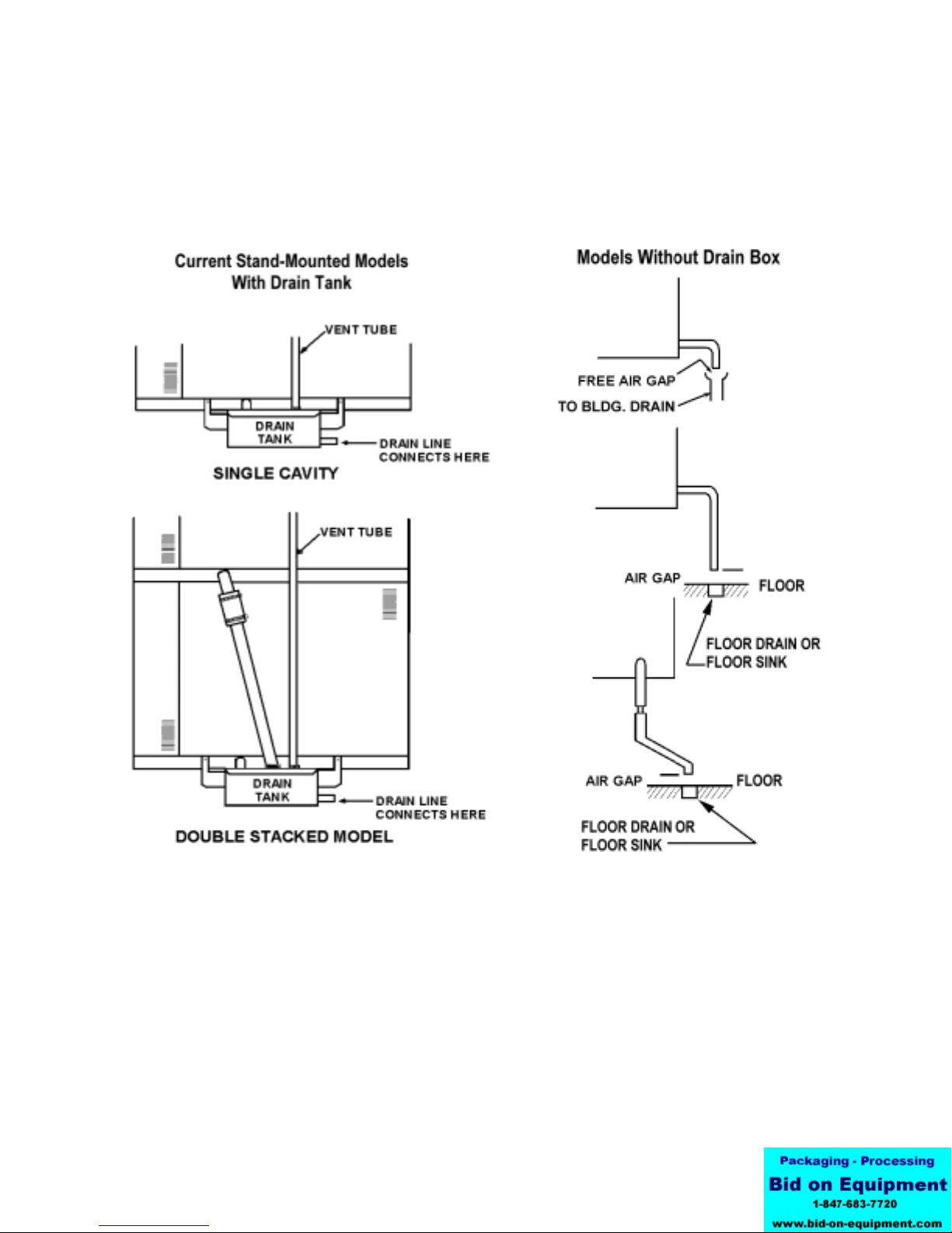
5. Drain Connection
a. Unit Without Drain Tank
(See figures on page 10)
A 1½ inch (4 cm) ID (CC10-G) or 2 inch (5
cm) ID hose (C/2-20G) may be attached to
the supplied drain outlet with a clamp. Do
not use plastic pipe, because the drain must
withstand very hot water.
WARN NG:
DO NOT CONNECT THE OVEN DRA N
D RECTLY TO A BU LD NG DRA N.
There must be a free air gap between the
end of the hose and the building drain. The
free air gap should be as close as possible
to the unit’s drain. There must also be no
other elbows or other restrictions between
the unit drain and the free air gap.
CAUT ON
DO NOT USE PLAST C P PE. DRA N MUST BE
RATED FOR VERY HOT WATER.
WARN NG
BLOCK NG THE DRA N S HAZARDOUS.
On a double stacked unit, there must be a
minimum of two inches free air gap on each
drain, as close to each oven as possible.
Double stacked units may only share a
common drain hose downstream of both
free air gaps.
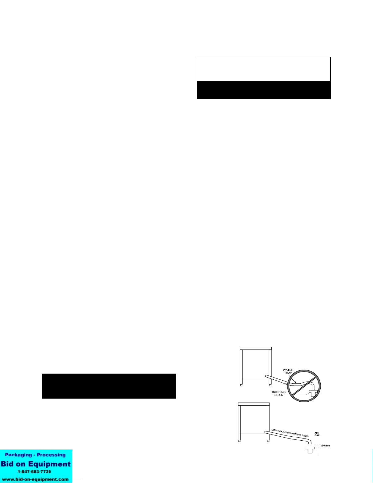
Install the drain line with a constant
downward pitch. This is especially important
for double-stack units. The bottom unit is
conceptually shown below.
MPORTANT: Do not allow any water traps in the
line. A trap can cause pressure to build up
inside the cavity during steaming, which will
make the door gasket leak.
NOTE: Improper drain connection will void the
warranty.
b. Units With Drain Tank
(See figures on page 10)
A hose may be attached to the supplied
drain elbow with a clamp. Use 1½ inch ID
hose for CC10-G or 2" ID hose for C/2-20G.
The hose may be connected directly to a
building drain since the drain tank has an air
vent, which eliminates the need for a free air
gap at the building drain.
Do not block the air vent in any way. Do not
attach anything to the vent tube or reduce its
size.
Do NOT use plastic pipe in the drain line,
because the drain must withstand very hot
water.

OM-CC-G and C/2-G
9
Convection Combo™ Utility Connections
NOTE: Remove right side panel to make connections
at terminal block in rear of control compartment.

OM-CC-G and C/2-G
10
Proper Drain Line Connections

OM-CC-G and C/2-G
11
nitial Start-Up
WARN NG
ANY POTENT AL USER OF THE EQU PMENT SHOULD BE TRA NED N SAFE AND CORRECT OPERAT NG
PROCEDURES.
After the Convection Combo™ has been installed,
test it to ensure that it is operating correctly.
1. Remove all literature and packing materials from
the interior and exterior of the unit.
2. Check that the cold water supply line is open and
that the fittings are not leaking.
3. Make sure that the gas supply line is open. On
newer units, turn the knob of the main gas valve
so that it is lined up with the pipe.
4. Turn on electrical service to the unit. Because
the unit will not operate without electrical
power, no attempt should be made to operate
the unit in the event of a power failure.
5. The control panel will not operate until the pilot
burner has been ignited. To light the pilot
burner, activate the pilot switch located next to
the main gas valve. Once the pilot ignition
sequence has been successfully completed, a
green light will glow, and power will be supplied
to the front panel.
6. The “trial for ignition” period is roughly 90
seconds. If the pilot burner does not light within
90 seconds of pilot switch activation, the ignition
system automatically stops the gas flow to the
pilot burner and cancels the ignition trial. If the
ignition trial is terminated, turn off the pilot switch
and repeat the trial for ignition. During initial
start-up, the pilot may require several trials in
order to bleed air from the gas piping.
Subsequent start-up should only require about
five seconds to achieve ignition.
NOTE: See Automatic Operation of Pilot at the end
of this section.
7. Once the pilot burner flame has been
established (the green light at the pilot switch is
on), all operator commands are executed via the
front control panel touch pads. See the
Operation section for details.
8. High Altitude Operation. At altitudes above
5,000 feet (1524m), the unit will not operate in
the Steamer or Combo Modes unless the altitude
is set. The Convection Combo™ is delivered
with the altitude set for 1000 feet as default. You
can program the altitude as follows:
a. If the unit is on, turn it off by pressing the ON
touch pad.
b. Press and hold the STEAM touch pad while
turning the unit on by pressing the ON touch
pad. The Time/Status display will show the
letters AL and a number representing the
altitude in thousands of feet. If the altitude
has not been set for your unit, the display
will be 0.
c. Enter an altitude value between 0 and 15,
using the numbered touch pads. For
example, if the unit will be operating at 7,000
feet, enter 7.
d. Press the START touch pad to accept the
change.
Altitude Metric Conversion
Altitude Setting
Feet Meters
1000 305 1
2000 610 2
3000 914 3
4000 1219 4
5000 1524 5
6000 1830 6
7000 2133 7
8000 2438 8
9000 2745 9
10000 3048 10
11000 3353 11
12000 3658 12
13000 3962 13
14000 4267 14
15000 4572 15
These controls are behind the sliding door on
the right side panel, facing the unit.

OM-CC-G and C/2-G
12
9. Select Fahrenheit or Celsius Temperatures.
The Convection Combo™ is delivered with the
Fahrenheit scale as default. To change the
temperature scale, hold the 5 key in, and press
ON. The Time/Status display will show dEG°F or
dEG°C. Press the 5 key to change from one to
the other. Press START to accept the change.
10. To Test Steamer Mode Operation, turn on the
unit. (For operating procedure details, see the
Operation section of this manual.) Clear time
from the time display. Close the door and press
the STEAM touch pad. (If the HOT light is on,
see Fast Cool in the Operation section.)
The WA T light will stay on while the steam
generator fills with and heats the water. It should
turn off within three minutes, and the READY
light should come on. This indicates that the
water is at its standby temperature. The timer
only controls operations in the Steamer Mode.
Enter a time and press START. (“Time” is set in
minutes and hours only. Seconds are not
displayed).
Examples: 2 minutes = 00:02
(Just press 2).
1 hour and 30 minutes = 01:30
(Press 1, 3, and 0, or press 9 and 0
the timer will change to 1:30)
The colon [:] between the numbers will blink and
the generator will begin to produce steam. Time
only counts down when the READY light is lit.
NOTE: You cannot change modes if the timer is
running.
WARN NG
WHEN YOU OPEN THE DOOR, STAY AWAY
FROM STEAM COM NG OUT OF THE UN T.
THE STEAM CAN CAUSE BURNS.
11. Test Combo Mode Operation, turn on the
power and clear any time from the Time/Status
display. Press the COMBO touch pad. Set the
COOK temperature to 350oF (175oC). The WA T
light will come on. It will remain on while (1) the
steam generator fills with water and heats it to its
standby temperature and (2) the air heater raises
the air temperature to 350oF. oth actions
should be completed in five to eight minutes,
starting with a cold unit. When the set
temperature is attained, the WA T light will go
off, and the READY light will come on. NOTE:
The timer does not control the oven in either the
Combo or Oven Modes.
12. Test Oven Mode Operation, turn on the power
and clear the Time/Status display. Press the
OVEN touch pad. Set the cook temperature to
350oF (175oC). The WA T light will come on.
Within eight minutes of a cold start, the WA T
light should go out and the READY light come
on. When that happens, turn the COOK setting
down to 320oF (160oC). The HOT light will come
on. Heat-up times may vary slightly with voltage
or water pressure differences.
13. To shut down the unit, switch off the power. The
pilot burner may also be turned off to conserve
energy.
14. If the Convection Combo™ works as described,
the unit is functioning correctly and is ready for
use.

OM-CC-G and C/2-G
13
Operation
WARN NG
ANY POTENT AL USER OF THE EQU PMENT SHOULD BE TRA NED N SAFE AND CORRECT OPERAT NG
PROCEDURES.
DO NOT OPERATE THE UN T AT ALL, UNLESS ALL FOUR REMOVABLE COOK NG COMPARTMENT
PART T ONS HAVE BEEN RETURNED TO THE R PROPER LOCAT ON.
DO NOT OPERATE TH S EQU PMENT W THOUT ELECTR C POWER.
NOTE: efore the control panel can be used, the pilot burner flame must be on. See “Initial Start-Up.”
A. Controls and ndicators
Operator controls are on the right front side of the
unit. Their use is described below:
1. Time Section
In Oven and Combo Modes, the timer functions
only as a “cooking time minute minder” and does
not turn the unit on or off. In the Steamer Mode,
however, it controls the steaming function.
a. Time/Status Display — Shows operating
time remaining in the Steamer, Oven or
Combo Mode. The timer counts down. If
the unit is equipped with, and operating in
the optional Hold Mode, the timer will count
up alternating with the word “Hold,” and will
show the total accumulated time that the
product has been holding. The display
shows operating time in “hours:minutes”
format. For example, entering 9 and 0 will
result in a display of 01:30.
b. Number touch pads — used to enter time
values.
c. CLEAR — Pressing this touch pad once
stops the beeper and resets the timer to the
time that was last set. Pressing twice clears
it to 00:00. At the end of a cooking period,
opening the door is the same as pressing
CLEAR once.
d. START — Press this touch pad to start the
timer. If the unit is in Steamer Mode, it will
also cause steaming to begin.
2. Status Lights
a. HOT — Indicates chamber temperature is
more than 15oF (8oC) over the set
temperature. (See Paragraph 5 in this
section)
b. SERV CE — Indicates that there is a
problem which might require a service call.
If there is such a problem, the beeper will
sound and the SERV CE light will be on
when you switch on the power. The unit
may continue to operate, depending on the
type of problem. Refer to the
Troubleshooting section to determine the
nature and severity of the problem.
c. WA T — Indicates the unit is either heating
or cooling toward the set temperature. The
HOT and WA T lights will both be on if the
chamber is more than 15oF (8oC) above the
set point.
d. READY — Indicates the unit is ready for
use.
e. CLEAN - Indicates the unit needs cleaning.
The unit will temporarily function if this light
is flashing.
3. Cooking Mode Selection
These touch pads are used to select the mode of
operation. If a mode is off, pressing the pad for
that mode will turn it on. If the mode is on,
pressing its pad will turn it off. A light just above
each pad indicates which has been selected.

OM-CC-G and C/2-G
14
Standard Operating Controls

OM-CC-G and C/2-G
15
a. STEAM — Selects steamer operation only.
b. COMBO — Selects superheated steam and
convection oven operation.
c. OVEN — Selects convection oven operation
only.
4. Power
The ON touch pad turns the unit on or off. When
power is on, the ON light just above the touch
pad is lit. Use of this pad does not reset the
controls. The unit will always come on in the
same mode it was in when shut down.
5. Temperature (TEMP) Section
a. The Cook display shows the selected
temperature in either Oven or Combo Mode.
It is blank in the Steamer Mode.
b. Turning the Temperature Control Knob
selects the cooking temperatures in 5oF
increments. The control ranges are:
Oven Mode 200-575oF (95-300oC)
Combo Mode 220-575oF (105-300oC)
NOTE: Maximum temperature is limited to
500°F when either the optional probe or
optional hold mode is in use.
6. Optional Features
If the following features are included, please
refer to the control panel guide which was
provided with the unit:
Cook Only Guide: P/N 121084
Programmable: P/N 121042
Probe & Hold: P/N 121072
B. Operating nstructions
1. Steam Mode
a. If the unit is off, switch on the electric power
by pressing the ON touch pad. (If the
SERV CE light comes on when you turn on
the power, see the Troubleshooting section).
b. If the power is already on, and there is a
number in the time display window, press
the CLEAR touch pad one or more times to
reset the time to zero.
NOTE: You cannot change operating modes
while the timer is running
c. The unit will be in the mode of operation in
which it was last used. ecause of this, the
indicator light for that mode will be lit. If the
unit is not already in the Steamer Mode,
press the STEAM touch pad. The STEAM
light will come on and the Cook display will
go blank.
d. If the unit was recently used in Oven or
Combo Mode, the HOT light may come on,
indicating that the cooking chamber is too
hot for use as a steamer. The unit can be
cooled quickly to the steaming temperature
range by leaving the door open or following
the Fast Cool procedure described near the
end of this section (Paragraph 4). With the
door open, the generator can fill and heat
the water to 200oF (93oC), but it cannot
produce steam.
WARN NG
WHEN YOU OPEN THE DOOR STAY AWAY
FROM ANY STEAM COM NG OUT OF THE UN T.
STEAM CAN CAUSE BURNS.
e. The WA T light will be on until the water
reaches 200oF (93oC). It will then turn off
and the READY light will come on. You are
now ready to steam foods in your
Convection Combo™.
f. Load the food into pans in an even, uniform
layer.
g. Carefully open the door and slide the pan or
pans onto the pan racks in the cooking
chamber. If you are only using one pan,
place it in the middle position. Close the
door.

OM-CC-G and C/2-G
16
h. Press the numbered touch pads to set the
cooking time. The time will appear in the
Time/Status display. If you enter the wrong
number, press the CLEAR touch pad to
erase the time from the display, and enter
the time again.
i. When the correct cooking time has been
entered, press the START pad. The colon in
the Time/Status display will blink and the
time will count down the cooking time. (The
unit must be READY before the timer can
count down.)
j. If you open the door during the cooking
period, steaming and the timer will stop (but
will not reset). When you close the door,
steaming and timing will resume.
WARN NG
WHEN YOU OPEN THE DOOR STAY AWAY
FROM ANY STEAM COM NG OUT OF THE UN T.
STEAM CAN CAUSE BURNS.
k. When the timer reaches zero, it stops steam
generation and sounds a beeper. Water in
the steam generator stays at its standby
temperature (200oF - 93oC). On older
models, the beeper will sound until the door
is opened or CLEAR is pressed.
l. Carefully open the door. If the food is
cooked, remove the pans using hot pads or
oven mitts to protect your hands.
m. After the display has counted down to zero,
opening the door or pressing CLEAR once
will reset the display to the time that was last
used. Pressing START will repeat the cook
cycle. If the same cooking time will be used,
you only need to press the number keys
when you first set that time.
n. After the Time/Status display has counted
down to zero, you can reset the time to zero
by either (1) opening the door and pressing
CLEAR or pressing CLEAR twice. A new
cooking time may then be set by using the
number keys.
2. Oven Mode
a. To use the Convection Combo™ as a
convection oven, switch on the electric
power by pushing the ON touch pad. (If the
SERV CE light comes on when you turn on
the power, see the Troubleshooting section).
If the door is closed and the cooking
temperature is above 250oF (120oC) the fan
will begin to operate.
b. If the power is already on, and there is a
number in the Time/Status display, press
CLEAR one or more times to reset the time
to zero.
NOTE: You cannot change operating modes
while the timer is running
c. The unit will power up in the mode in which it
was last used. ecause of this, the indicator
light for that mode will be lit. If the unit is not
already in the Oven Mode, press the OVEN
touch pad. The OVEN light will come on and
the oven fan will operate.
d. Use the Temperature Control Knob to set
the desired cooking temperature between
200o and 575o F (93o to 300o C). NOTE:
Maximum temperature is limited to 500°F
when the either the optional probe or
optional hold mode is in use. The
temperature will appear in the Cook display.
Unless the cooking chamber is already at or
above the selected temperature, the unit will
start heating and the WA T light will come
on.
e. If the unit was recently used at a
temperature 15oF (8oC) or more over the
selected temperature, the HOT and WA T
lights will come on. The unit can be cooled
quickly to the desired cooking temperature
by leaving the door open or following the
Fast Cool procedure described near the end
of this section (Paragraph 4).
f. The READY light will indicate when the oven
is at the desired temperature.
g. Load the food into the pan or pans in a
uniform layer.
h. The Convection Combo™ will operate in
Oven Mode with the timer either on or off. If
you want to time cooking, press the
numbered pads in the Time/Status portion of
the control panel to set the cooking time.
The time will appear in the Time/Status
display . If you enter the wrong number,
press CLEAR to erase the time from the
display, and reenter the time. Remember
that the timer does not control the unit in
the Oven Mode.

OM-CC-G and C/2-G
17
i. Open the door and slide the pan or pans
onto the pan racks in the cooking chamber.
If you are only using one pan, place it in the
middle position. Close the door.
j. If the correct time has been set on the timer,
press the START pad. The colon [:]
between the numbers in the Time/Status
display will blink and the time will count
down the cooking time. When the timer has
counted down to zero, it will sound a beeper.
This sound will continue until the door is
opened or the CLEAR pad is pressed.
k. To stop cooking, take the pans out of the
oven using hot pads or oven mitts to protect
your hands from the hot pans. The unit will
continue heating to keep the chamber at the
set temperature until the temperature control
is reset, or the power is shut off.
WARN NG
PANS AND NTERNAL PARTS OF THE OVEN
W LL BE VERY HOT. AVO D CONTACT W TH
HOT SURFACES.
l. Opening the door during operation shuts off
power to the heaters and fan and stops the
timer, but it has no other effect on the
controls. When the door is closed, operation
continues. Note that cooking time will be
extended by the period the door was open.
3. Combo Mode
a. If the unit is off, switch on the electric power
by pressing the ON touch pad. (If the
SERV CE light comes on when you turn on
the power, see the Troubleshooting section).
If the door is closed and the cooking
temperature is above 200oF (93oC) the fan
will begin to operate.
b. If the power is already on, and there is a
number in the time display window, press
the CLEAR touch pad one or more times to
reset the time to zero.
NOTE: You cannot change operating modes
while the timer is running
c. The unit will power up in the mode of
operation in which it was last used. ecause
of this, the indicator light for that mode will
be lit. If the unit is not already in the Combo
Mode, press the COMBO touch pad. The
COMBO light will come on and if the steam
generator is not already full, water will flow
into it and begin heating.
d. Use the Temperature Control Knob to set
the desired oven temperature between 220
and 575oF (105 to 300oC). The temperature
will appear in the Cook display.
e. If the unit was recently used at a
temperature more than 15oF (-8oC) higher
than the temperature selected, the HOT and
WA T lights will turn on. The unit can be
cooled quickly by leaving the door open or
following the Fast Cool procedure described
near the end of this section (Paragraph 4).
WARN NG
WHEN YOU OPEN THE DOOR STAY AWAY
FROM ANY STEAM COM NG OUT OF THE UN T.
STEAM CAN CAUSE BURNS.
f. The WA T light will be on until the water in
the steam generator reaches boiling and the
air in the cooking chamber reaches the set
temperature. It will then turn off and the
READY light will come on to indicate that the
oven is at the desired temperature.
g. The unit will operate in Combo Mode with
the timer either on or off. If you want to time
the cooking, press the numbered pads in the
Time/Status portion of the control panel to
set the cooking time. The time will appear in
the Time/Status display. If you enter the
wrong number, press the CLEAR touch pad
to erase the time from the display, and enter
the time again. The timer does not control
the unit in Combo Mode.
h. Load the food into the pan or pans in a
uniform layer.

OM-CC-G and C/2-G
18
WARN NG
WHEN YOU OPEN THE DOOR STAY AWAY
FROM ANY STEAM COM NG OUT OF THE UN T.
STEAM CAN CAUSE BURNS.
i. Open the door and slide the pan or pans
onto the pan racks in the cooking chamber.
If you are only using one pan, place it in the
middle position. Close the door.
j. If the timer has been set, press the START
pad. The colon [:] between the numbers in
the Time/Status display will blink and the
time will count down the cooking time.
When the timer has counted down to zero, it
will sound a beeper. This beeping will
continue until the door is opened or the
CLEAR pad is pressed.
k. To stop cooking, take the pans out of the
oven using hot pads or oven mitts to protect
your hands from the hot pans. The unit will
continue steaming and heating the oven at
the set temperature until the temperature
control is reset or the power is shut off.
4. Fast Cool
a. When the HOT indicator is lit and the timer is
cleared, the unit can be cooled quickly by
opening the door and pressing START. The
fan will operate, and the Time/Status display
will show the word “COOL.” This is the only
time the fan operates with the door open.
WARN NG
DO NOT PUT HANDS OR OTHER OBJECTS
NTO THE COOK NG CHAMBER DUR NG THE
FAST COOL OPERAT ON. THE ROTAT NG FAN
CAN BE HAZARDOUS.
b. To stop the Fast Cool operation, press any
touch pad or close the door.
5. Shutting Down
a. Press the touch pad for the mode in which
the unit is operating.
b. Switch off the power by pressing the ON
touch pad.
Leave the door at least partially open, if local
sanitation regulations permit.

OM-CC-G and C/2-G
19
Cleaning
To keep your Convection Combo™ in proper operating condition and to make the cleaning process easier,
cleaning should be a daily activity.
A. Suggested Tools and Cleaners
1. Mild detergent
2. Stainless steel exterior cleaner such as
Zepper®
3. Steam generator de-liming agent, such
as Groen Delimer Descaler, (P/N
114800) Lime-A-Way® or an equivalent.
A liquid de-liming agent will be easier to
use than crystals or powders. See the
warning about chlorides below.
4. De-greaser, such as EncompasS®, Groen
Degreaser, Malone 34®, Puritan
Puribrute®, or Con-Lie®
5. Cloth or sponge
6. Plastic wool or a brush with soft bristles
7. Spray bottle
8. Measuring cup
9. Nylon pad
10. Towels
11. Plastic disposable gloves
B. PROCEDURE
1. Exterior Cleaning
a. Prepare a warm solution of the mild
detergent as instructed by the supplier.
Wet a cloth with this solution and wring it
out. Use the moist cloth to clean the
outside of the unit. Do not allow freely
running liquid to touch the controls, the
control panel, any electrical part or any
open louver.
b. To remove material which may be stuck to
the unit, use plastic wool, a fiber brush, or
a plastic or rubber scraper with a
detergent solution.
c. Stainless steel surfaces may be polished
with a recognized stainless steel cleaner
such as Zepper®.
d. For glass surfaces, use a mild detergent
without abrasives or a high quality
glass/surface cleaner with a clean cloth or
sponge. Do not spray hot glass with water
or chemicals. This could cause the glass to
break from thermal shock.
e. Use a mild soap without abrasives and warm
water to clean the door gasket. DO NOT
use caustic oven cleaners on the door
gasket, as this will damage it.
PRECAUT ONS
WARN NG
D SCONNECT THE POWER SUPPLY
BEFORE CLEAN NG THE OUTS DE OF
THE UN T.
KEEP WATER AND CLEAN NG
SOLUT ONS OUT OF CONTROLS AND
ELECTR CAL COMPONENTS. NEVER
HOSE OR STEAM CLEAN ANY PART OF
THE UN T.
BE CAREFUL CLEAN NG THE TOP FLUE
COVER AND THE OVEN TOP. BOTH
AREAS MAY BE VERY HOT.
DON’T M X DE-L M NG AGENTS (AC D)
W TH DE-GREASERS (ALKAL )
ANYWHERE N THE UN T
AVO D CONTACT W TH ANY CLEANERS,
DE-L M NG AGENT OR DE-GREASER AS
RECOMMENDED BY THE SUPPL ER.
MANY ARE HARMFUL. READ THE
WARN NGS AND FOLLOW THE
D RECT ONS!
EVEN WHEN THE UN T HAS BEEN SHUT
OFF, DON’T PUT HANDS OR TOOLS NTO
THE COOK NG CHAMBER UNT L THE FAN
HAS STOPPED TURN NG.
DON’T USE ANY CLEAN NG OR DE-
L M NG AGENT THAT CONTA NS ANY
SULFAM C AGENT OR ANY CHLOR DE,
NCLUD NG HYDROCHLOR C AC D (HCl).
TO CHECK FOR CHLOR DE CONTENT
SEE ANY MATER AL SAFETY DATA
SHEETS PROV DED BY THE CLEAN NG
AGENT MANUFACTURER.
UN T MAY BE HOT. TAKE PRECAUT ONS
TO PREVENT CONTACT W TH HOT
SURFACES.
To clean the cooking chamber and/or de-lime the steam
generator of the CC10-G or C/2-20G, a special
sequence of operations (the Clean Cycle) has been
programmed into the Convection Combo™ computer.
To run this automatic Clean Cycle for cleaning, de-
liming or both actions at the same time, follow the
instructions outlined on the following page.
MPORTANT
DO NOT USE ANY METAL MATER AL (SUCH AS METAL SPONGES) OR METAL IMPLEMENTS (SUCH AS A SPOON, SCRAPER OR
WIRE RUSH) THAT MIGHT SCRATCH THE SURFACE. SCRATCHES MAKE THE SURFACE HARD TO CLEAN AND PROVIDE PLACES
FOR ACTERIA TO GROW. DO NOT USE STEEL WOOL, WHICH MAY LEAVE PARTICLES IM EDDED IN THE SURFACE WHICH COULD
EVENTUALLY CAUSE CORROSION AND PITTING.

OM-CC-G and C/2-G
20
WARN NG
DO NOT SPRAY OR CLEAN THE DOOR WH LE
HOT. GLASS BREAKAGE MAY OCCUR F THE
DOOR S RAP DLY COOLED W TH WATER.
f. Always check
the jumper cord
between the oven
front panel and
the door after
cleaning. Make
sure that it is
properly positioned
as shown to
prevent damage.
2. nterior CLEAN NG STEPS
For the (2)CC-10G and (2)C/2-20G double-stacked
units, the cleaning processes must be performed
on each cavity. When double-stack units are being
cleaned, wait five minutes after starting the first oven
clean cycle (Time/Status display will show CL:40)
before you start to clean the second cavity.
Clean Cooking
Chamber Only
De-Lime Steam
Generator Only
Clean Chamber and
De-Lime Generator
Omit step 3 Omit step 2 Perform all steps
in order
efore beginning this procedure, make sure the oven
HOT light is not on. If the HOT light is on, use the
FAST COOL instructions on page 18 to cool the
oven cavity.
WARN NG
UN T MAY BE HOT. DO NOT TOUCH HOT
SURFACES.
DO NOT PUT HANDS OR OTHER OBJECTS
NTO COOK NG CHAMBER WH LE
CONVECT ON COMBO™ S OPERAT NG. THE
ROTAT NG FAN CAN BE HAZARDOUS.
STEP 1
After cooling the oven to 200ºF (90ºC) or less,
take the oven out of any mode in which it may
have been operating. (Wait at least two minutes,
or until the steam generator starts to fill, before
adding an deliming solution.) Enter 99 into the
timer. The Time/Status display will read
CC or CL.
WARN NG
BEFORE REACH NG NTO THE OVEN TO
REMOVE PART T ONS, EX T THE FAST COOL
MODE BY PRESS NG ANY BUTTON OR BY
CLOS NG AND REOPEN NG THE DOOR. DO
NOT REACH N THE OVEN UNT L THE FAN HAS
STOPPED MOV NG.
OVEN MAY BE HOT — WEAR GLOVES OR USE
OVEN M TTS TO AVO D BURNS.
DO NOT OPERATE THE UN T N ANY MODE
UNLESS ALL FOUR REMOVABLE PART T ONS
HAVE BEEN RETURNED TO THE R PROPER
LOCAT ONS.
STEP 2
Make sure to clean all food particles out of the
drain.
On a daily basis, follow the degreaser supplier’s
instructions, and apply degreaser to the entire
cooking cavity and pan racks.
Once a week, remove oven racks and partitions
in order. Use an oven mitt if the oven is hot. To
remove partitions:
Left — The left partition includes a back
plate and an air distribution baffle. Lift up to
disengage the four hooks from their support
posts and remove the partition from the
chamber (see pictures on next page).
Right — The right partition includes a large,
circular, flared opening that is centered in
front of the fan. Push upward to disengage
the four hooks from their support posts and
remove the partition from the chamber.
ottom — The bottom partition has a small
circular pattern of drain holes. Lift it directly
up and off from its four support posts.
This manual suits for next models
5
Table of contents
Other Groen Oven manuals