Gronomics WRC PB 28-48 User manual

www.gronomics.com East Bethel, MN USA 763-753-7374
Continued
WRC Patio Bar
Assembly Instruction
1
Parts Identification Box 1
Stack matching pieces in piles. Using
the parts list, locate and count the
individual pieces and verify that you
have received the correct number of
pieces.
If any pieces are missing or
replacement parts are required,
contact Gronomics at 1-855-299-
6727.
NOTE: It is recommend to place a
protective layer between the ground
and the pieces during assembly.
This will help prevent damage to the
pieces.
Parts List Box 1 of 2
ITEM QTY. PART # DESCRIPTION
1 1 28481 Bar Top, 47” x 26-1/4” x 1-5/8”
2 1 T-28484 Front Panel Tongue & Groove Board (Top) 5-1/4” x 34-3/4” x 5/8”
3 7 28484 Front Panel Tongue & Groove Boards 5-1/4” x 34-3/4” x 5/8”
4 2 K-28484 Toe Kick Plate (TK) (one w/Logo) 5-1/4” x 34-3/4” x 5/8”
5 4 SS-28485 Sand Shelf, Tongue & Groove Boards (SS) 5-1/4” x 34-3/4” x 5/8”
6 4 BS-28485 Bottom Shelf, Tongue & Groove Boards (BS) 5-1/4” x 34-3/4” x 5/8”
7 4 TS-28485 Top Shelf, Tongue & Groove Boards (TS) 5-1/4” x 34-3/4” x 5/8”
8 1 SS-21434 Sand Shelf, Narrow Board (SS) 2-1/4” x 34-1/2” x 5/8”
9 1 BS-21234 Bottom Shelf, Narrow Board (BS) 2-1/2” x 34-1/2” x 5/8”
10 1 TS-21234 Top Shelf, Narrow Board (SS) 2-1/2” x 34-1/2” x 5/8”
11 1 28486 Foot Rest, 3-1/4” x 38-3/4” x 3-1/4”
12 1 HTUS 28-28 Umbrella Stand
13 40 CS8-112ZY Screws, GRK (front panel & toe kick boards) 8 x 1-1/2”
14 6 RSS14-212ZY Screws, RSS GRK (table top) 1/4” x 2-1/2”
15 4 RSS14-312ZY Screws, RSS GRK (foot rest) 1/4” x 3-1/2”
1
23
456789
12
12
10
10
11
11
13
13
14
14
15
15
PB 28-48
Packaged & Inspected by: Date:
Torx® T15
Torx® T25
Torx® T25
14
14
15
15
13
13

www.gronomics.com East Bethel, MN USA 763-753-7374
Continued
2
Parts Identification Box 2
Using the parts list, locate and count
the individual pieces and verify that
you have received the correct number
of pieces.
If any pieces are missing or
replacement parts are required,
contact Gronomics at 1-855-299-
6727.
NOTE: It is recommend when to place
a protective layer between the ground
and the pieces during assembly.
This will help prevent damage to the
pieces.
Parts List Box 2 of 2
ITEM QTY. PART # DESCRIPTION
16 2 28482 Side, 21-1/2” x 40-1/2” x 3-1/8”
16
16
16
16
Make sure the working surface is level and a protective layer
is placed on the ground. Lay the 21-1/2” x 40-1/2” x 3-1/8”
bar sides (Item 16) on the floor with the ends marked (Top)
facing you and the cleats facing each bar side.
Bar Side Assembly
3
Large
Cleat
Large
Cleat
16
16
16
16
Top Top

www.gronomics.com East Bethel, MN USA 763-753-7374
Continued
Place a 5-1/4” x 34-3/4” x 5/8” front panel board (marked
top) (Item 2) flush with the top of the bar sides. Do not
fasten at this time.
Next, place a 5-1/4” x 34-3/4” x 5/8” front panel tongue &
groove board (Item 3) at the bottom of the bar sides and
flush with the bottom of the bar sides. Do not fasten at this
time.
NOTE: Make sure bar sides are tight to the front panel
board ends and flush with the bar side ends.
Secure the front panel board (marked top) to the bar sides
using two 1-1/2” screws (Item 13 ) on each end of the front
panel board (marked top).
NOTE: Temporaily secure the front panel board located at
the bottom of the bar sides using one 1-1/2” screw on each
end.
2
Top Front Panel Board
Straight Cut Edge
Grooved Edge
Front Panel Board
(grooved edge
located flush at the
bottom of bar sides)
Flush
Flush
Temporaily
Secured Board
4
3
Bar Side And Front Panel Board Assembly
13
13
13
13
Flush Flush
Front Panel Board Assembly
5
Install the six remaining 5-1/4” x 34-3/4” x 5/8” front panel
tongue & groove boards (Item 3), working from the top of
the bar sides to the bottom of the bar sides.
Make sure the tongue & groove on each board is fully
seated together and secure boards with two 1-1/2”screws
(Item 13) at each end.
Repeat procedure for the 5 remaining 5-1/4” x 34-3/4” x
5/8” front panel tongue & groove boards.
3
Top
Bottom
Top
Install
Screws
Install
Screws
13
13

www.gronomics.com East Bethel, MN USA 763-753-7374
Continued
Final Front Panel Board Assembly
6
When the last 5-1/4” x 34-3/4” x 5/8” front panel tongue &
groove board (Item 3) is secured, remove the screws from
the temporaily secured front panel board.
Seat the temporaily secured front panel board to last
secured front panel board (Item 3) and secure with 1-1/2”
screws (Item 13).
Temporaily Secured Board
3
13
13
Stand the tiki bar upright with the ends marked top facing up.
Seat the three 5-1/4” x 34-3/4” x 5/8” sand shelf tongue &
groove boards marked (SS) (Item 5) and the 2-1/4” x 34-3/4” x
5/8” narrow sand shelf board marked (SS) (Item 8) (as shown
below).
Place the boards on top of the lower cleats with the narrow
sand shelf board facing you.
Sand Shelf Assembly
7
Narrow Sand
Shelf Board
58
Lower Cleats
Narrow Sand Shelf Board

www.gronomics.com East Bethel, MN USA 763-753-7374
Continued
Bottom Shelf Assembly
9
Narrow Bottom
Shelf Board
69
Narrow Bottom Shelf Board
Seat the three 5-1/4” x 34-3/4” x 5/8” bottom shelf tongue &
groove boards maked (BS) (Item 6) and the 2-1/2” x 34-3/4”
x 5/8” narrow bottom shelf board marked (BS) (Item 9) (as
shown below).
Place the boards on the top of cleats with the narrow bottom
shelf board facing you.
Position the two 5-1/4” x 34-3/4” x 5/8” toe kick plates
marked (TK) (Item 4) (one w/Logo) as shown.
NOTE: The top toe kick plate w/ Logo must be flush with the
top of the cleats.
Install 1-1/2” screws (Item 13) into the pre-drilled holes on
the backside of the toe kick plates on each end (see figure
below). Tighten screws.
(It is recommended to fill the lower compartment
with sand to provide weight for bar stability if used
outdoors).
Toe Kick Plate Board Assembly
8
Cleats
Top of TK Board Flush with Top of Cleats
4
13
13
13
13
Flush with Top of Cleat

www.gronomics.com East Bethel, MN USA 763-753-7374
Continued
Top Shelf Assembly
Narrow Top
Shelf Board
7
Narrow Top Shelf Board
Seat the three 5-1/4” x 34-3/4” x 5/8” top shelf tongue &
groove boards maked (TS) (Item 7) and the 2-1/2” x 34-3/4” x
5/8” narrow top shelf board marked (TS) (Item 10) (as shown
below).
Place the boards on the top of cleats with the narrow top shelf
board facing you.
10
10
Place the 47” x 26-1/4” x 1-5/8” bar top
(Item 1) (as shown) onto the top of the
bar sides.
Table Top Assembly
11
11
1
Beveled Edge of Bar Top Facing Up
10
10

www.gronomics.com East Bethel, MN USA 763-753-7374
Center the bar top (Item 1) at the front and the back
of the bar (see Figure A, below).
Center the bar top (Item 1) on each end of the bar
(see Fiqure B, upper right).
When the bar top is centered, secure the bar top with
three 2-1/2” screws (Item 14) on each side, using the
pre-drilled holes in the cleats (see Figure C, lower
right).
Table Top Assembly Continued
12
12
1
Install
Screws
Aproximately
2-3/4” Front
Aproximately
2-3/4” Back
Aproximately
4-1/4”
Bar Top End
Aproximately
2-3/4” Back
Aproximately
2-3/4” Front
Aproximately
4-1/4”
Bar Top End
Aproximately
4-1/4”
Bar Top End
Aproximately
4-1/4”
Bar Top End
Figure A
Figure B
Figure C
14
14
1
Back View
Side View

www.gronomics.com East Bethel, MN USA 763-753-7374
At the front side of the bar, measure 12” up from the bottom
and place a mark on each side. Place the top of the 3-1/4” x
38-3/4” x 3-1/4” foot rest (Item 11) at the mark on each side,
make sure the foot rest is centered side to side and secure
with four screws (Item 15).
Foot Rest Assembly
13
13
12” 12”
15
15
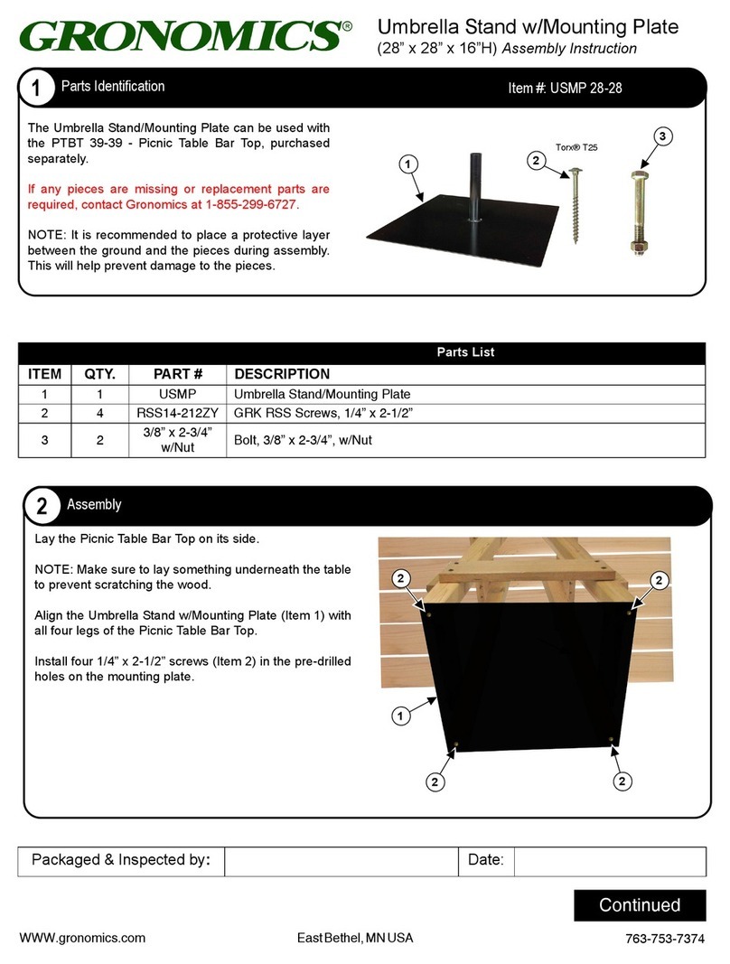
Place the umbella stand (Item 12) onto the top
shelf (as shown).
NOTE: Use the umbrella to align the umbrella
stand.
Align the umbrella stand hole with the table top
hole.
Install two 1-1/2” screws (Item 13 ) through the
top shelf board and into the umbrella stand.
NOTE: Sand is required in the lower
compartment below the bottom shelf if an
umbrella is used.
Umbrella Stand Installation (Optional)
14
14
TableTop Hole
12
12
Install Screws
13
13
11
11
Front View
Other Gronomics Patio Furniture manuals
Popular Patio Furniture manuals by other brands

sun garden
sun garden Easy Sun Repair instructions

Polywood
Polywood PALM COAST ADIRONDACK HNA10 Assembly instructions

HOMEDEPOT
HOMEDEPOT P155 instruction manual

FLORABEST
FLORABEST Z27443A Assembly and Safety Advice

Members Mark
Members Mark YJAUC-165A Assembly instructions & user manual

HAMPTON BAY
HAMPTON BAY 270-8-38A-RED Assembly instructions

Home Decorators Collection
Home Decorators Collection FLA60441-2PK Use and care guide

Sunnydaze Decor
Sunnydaze Decor JVA-360 manual

Alice's Garden
Alice's Garden ACATIUM AF3007 Directions for use

Royal garden
Royal garden YJAF-819A Use and care guide

BCP
BCP SKY5949 instruction manual

Home Styles
Home Styles 88 5552 66 quick start guide