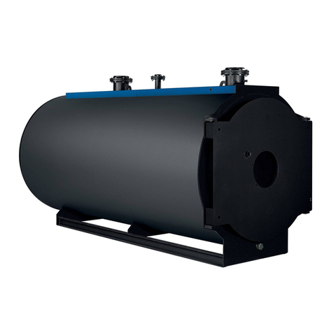
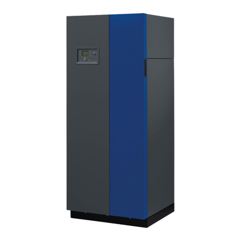
Groupe Atlantic Varmax 120 Quick start guide

MANUFACTURER:
1 route de Fleurville - BP 55
FR - 01190 PONT-DE-VAUX
SITE DE PONT-DE-VAUX
Installation,
use and
maintenance
instructions
C
O
L
L
E
C
T
I
V
E
P
R
O
D
U
C
T
VARMAX
GAS CONDENSING BOILER
120 to 450 kW
with modulating burner
for natural gas and propane gas
Document No. 00BNO9061-L / 18.04.16
FR EN DE ES IT NL
00BNO3000-#


18.04.16 Page 3 / 146
VARMAX - Installation, Use and Maintenance
CONTENTS
1. WARNINGS AND RECOMMENDATIONS..............................................................................6
1.1. Transport and storage ................................................................................................................................... 6
1.2. Symbols used in this document. ................................................................................................................... 6
1.3. Qualification of personnel for installing, adjusting, using and maintaining the equipment ............................ 6
1.4. Safety instructions......................................................................................................................................... 6
1.5. Water characteristics..................................................................................................................................... 7
2. APPROVALS ........................................................................................................................10
2.1. Compliance with European Directives ........................................................................................................ 10
2.2. Regulatory installation conditions................................................................................................................ 10
2.3. Gas category............................................................................................................................................... 10
2.4. Gas supply pressures ................................................................................................................................. 11
3. TECHNICAL SPECIFICATIONS ...........................................................................................12
3.1. Dimensions ................................................................................................................................................. 12
3.2. Doorways .................................................................................................................................................... 14
3.3. Combustion at 15°C and 1013 mbar........................................................................................................... 15
3.4. Conditions of use ........................................................................................................................................ 17
3.5. Electrical connection ................................................................................................................................... 17
4. INSTALLATION.....................................................................................................................18
4.1. Installation of the air filter and filter matting................................................................................................. 18
4.2. Installing the boiler ...................................................................................................................................... 19
4.3. Opening / closing of casing doors ............................................................................................................... 20
4.4. Removing the control panel (MMI) .............................................................................................................. 20
4.5. Removing / refitting the casing doors.......................................................................................................... 21
4.6. Removing / refitting side panels .................................................................................................................. 22
4.7. Removing / refitting the top panel ............................................................................................................... 22
4.8. Step............................................................................................................................................................. 23
4.9.Changing the gas type (G20 to G31) ........................................................................................................... 24
4.10.Exhaust connection .................................................................................................................................... 26
4.11.Hydraulic connection .................................................................................................................................. 34
4.12.Gas connection .......................................................................................................................................... 36
4.13.Electrical connection .................................................................................................................................. 36

Page 4 / 146 00BNO9061-L
VARMAX - Installation, Use and Maintenance
5. COMMISSIONING.................................................................................................................40
5.1. Unlocking the boiler..................................................................................................................................... 40
5.2. Pre-commissioning checks ......................................................................................................................... 40
5.3. Commissioning............................................................................................................................................ 41
6. POST-COMMISSIONING CHECK ........................................................................................42
6.1. Condensate removal ................................................................................................................................... 42
6.2. Gas supply .................................................................................................................................................. 42
7. MAINTENANCE OPERATIONS ...........................................................................................43
7.2. Verification of the boiler's environment........................................................................................................ 44
7.3. Replacing the air filter matting..................................................................................................................... 44
7.1. Boiler draining ............................................................................................................................................. 44
7.4. Verification of ignition and ionisation electrodes ......................................................................................... 45
7.5. Siphon cleaning........................................................................................................................................... 46
7.6. Checking the combustion circuit's gas-tightness......................................................................................... 46
7.7. Checking combustion quality ...................................................................................................................... 47
7.8. Setting the gas valve................................................................................................................................... 48
7.9. Gas filter cleaning ....................................................................................................................................... 50
7.10.Cleaning exchangers and changing seals.................................................................................................. 51
7.11.Cleaning the burner and changing the seals .............................................................................................. 53
8. END-OF-LIFE CYCLE OF THE APPARATUS......................................................................56
9. HYDRAULIC DIAGRAMS AND SETTINGS .........................................................................57
9.1. Selection flow diagram ................................................................................................................................ 57
9.2. Symbols used in the diagrams .................................................................................................................... 59
9.3. List of diagrams........................................................................................................................................... 59
10. LIST OF SPARE PARTS.....................................................................................................116
11. TABLE OF CUSTOMER SETTINGS ..................................................................................127
12. ANNEX A.............................................................................................................................144

18.04.16 Page 5 / 146
VARMAX - Installation, Use and Maintenance

Page 6 / 146 00BNO9061-L
VARMAX - Installation, Use and Maintenance
1. WARNINGS AND RECOMMENDATIONS
PLEASE READ THIS MANUAL CAREFULLY BEFORE INSTALLING,
CARRYING OUT MAINTENANCEAND USING THE BOILER. IT CONTAINS
IMPORTANT SAFETY INFORMATION.
1.1. Transport and storage
The boiler:
- must be stored vertically in an environment where the temperature is
between -20°C and +55°C, and where relative humidity is between 5%
and 95%;
- must not be stacked,
- must be protected from humidity.
1.2. Symbols used in this document.
INFORMATION: This symbol draws attention to comments.
!WARNING: Not following these instructions may lead to
damage when installing or to other objects.
!DANGER: Not following these instructions may cause
injuries and serious material damage.
DANGER: Not following these instructions may cause
electrocution.
1.3. Qualification of personnel for installing, adjusting, using and
maintaining the equipment
Boiler installation, adjustment and maintenance operations must be
conducted by a qualified and approved professional in accordance with
prevailing local and national regulations. These operations may require work
to be carried out with the power turned on and the casing doors (on the front
of the boiler) open.
Basic utilisation operations must be carried out with the casing doors closed.
1.4. Safety instructions
• Always switch the boiler off and shut off the general gas supply before
carrying out any work on the boiler.
• After performing work on the boiler (maintenance or breakdown), check
that there are no gas leaks from the installation.
INFORMATION:
VARMAX boilers are available with 2/3 tappings or 4 tappings. It is not
possible to transform a version with 2/3 tappings into a version with
4 tappings and vice versa.

18.04.16 Page 7 / 146
VARMAX - Installation, Use and Maintenance
!DANGER:
If you smell gas:
• Do not use a naked flame, do not smoke, do not turn on electrical
contacts or switches.
• Cut off the gas supply.
• Air the premises.
• Look for the leak and repair it.
!DANGER:
If you see smoke:
• Switch off the boiler.
• Air the premises.
• Look for the leak and repair it.
DANGER:
This boiler's earth bonding is ensured with connecting cables (green/
yellow) and specific attachment screws. During any dismantling work,
make sure you reconnect the cables concerned; it is IMPERATIVE to
reuse the original attachment screws.
1.5. Water characteristics
The following rules apply as soon as the boiler is commissioned and remain
valid until the product's end-of-life.
!DANGER: It is forbidden to use water containing glycol.
1.5.1. Preparation of the water circuit before commissioning the boiler
For all installation work (new or renovation), the water network pipes must be
meticulously cleaned. The purpose of cleaning prior to commissioning is to
remove germs and residues which are the cause of deposits.
In new installations in particular, residue from grease, oxidised metal and
even copper micro deposits must be removed.
In renovated installations, cleaning should focus on removing sludge and the
products of corrosion formed when the unit was last in operation.
There are two types of methods for cleaning and removing sludge: a high
intensity approach that takes a few hours and a slower, more gradual
approach that takes several weeks. This first type of cleaning must be done
before connecting the new boiler, and with the second type, a filter should be
installed on the back of the boiler to capture loosened deposits.
Cleaning prior to commissioning helps to improve the equipment's
performance, reduce energy consumption and fight against scaling and
corrosion. This operation must be done by a professional (water treatment).

Page 8 / 146 00BNO9061-L
VARMAX - Installation, Use and Maintenance
1.5.2. Protecting the unit against scaling
Water naturally contains dissolved calcium ions and carbonates that cause
scaling (calcium carbonate) to form. To prevent excessive deposits, take
precautions with regard to the water used to fill the unit TH < 10°f
Water must be added during the life of the boiler. The new water adds scaling
to the water system. The amount of fill water and the amount of make-up
water added throughout the unit's lifecycle must not be more than three times
the water capacity of the heating system. Also, the hardness of the make-up
water must be controlled. Make-up water: TH < 5°f
Adding a large amount of untreated water always contributes a significant
amount of scaling. To monitor this and to detect problems, a system water
meter must be installed.
Failure to comply with these guidelines (such that the fill water plus the make-
up water is more than three times the water capacity of the heating system)
requires a full cleaning (to remove sludge and scaling) to be performed.
Additional precautions are required for operation:
- When the unit has a water softener, the equipment must be inspected
on a regular basis in order to ensure that it is not outputting chloride-
rich water into the system. The concentration of chlorides must always
remain below 50 mg/litre.
- To prevent the build-up of calcium deposits (such as on exchange
surfaces), the unit should be brought into service slowly, starting by
operating at a low power with high primary water flow.
- When the tap water lacks the desired qualities (e.g. high level of
hardness), water treatment is required. The fill water must be treated,
and whenever new water is added, the make-up water must also be
treated.
- Installations with multiple boilers require all of the boilers to be started
simultaneously at minimal power. Doing this prevents the calcium in the
water from depositing on the exchange surfaces of the first boiler.
- When working on the unit, avoid draining it completely; only the required
parts of the system are to be drained.
The rules listed above are designed to minimise scaling on the exchange
surfaces and thus to increase the life of the boilers.
To optimise the equipment's operation, remove lime scale deposits. This
must be done by a specialised company. Also, before putting the unit into
service, verify that the heating system is not damaged (e.g. leaks). If it has
excessive scaling, the unit's settings for operation and for water treatment
must be adjusted.
1.5.3. Protecting steel and stainless steel boilers against corrosion
Corrosion can affect the iron components used in boilers and heating
systems, which is directly related to the presence of oxygen in the water
heater's water. Dissolved oxygen that enters the unit when it is being filled
for the first time reacts with the equipment materials and quickly disappears.
Without refreshing the oxygen through significant contributions of water, the
unit might not experience any damage whatsoever.
However, it is important to follow the sizing rules and installation guidelines
in order to prevent oxygen from continuously flowing into the heating water.

18.04.16 Page 9 / 146
VARMAX - Installation, Use and Maintenance
These rules include:
- Opt for an expansion vessel with a membrane rather than an open
expansion vessel that allows direct passage.
- Make sure pressure in the equipment is more than 1 bar when cold.
- Remove non-gas-tight components (permeable) and use gas-tight
equipment instead.
If the guidelines above are followed, the unit's system water has the proper
characteristics to last a long time: 8.2 < pH < 9.5 and concentration in
dissolved oxygen < 0.1 mg/litre.
If there is a chance that oxygen could enter the unit, you must take additional
precautions. Adding an oxygen scavenger (e.g. sodium sulphite) is highly
recommended. We recommend you contact specialised companies for
water treatment issues, which will be able to suggest:
- the appropriate treatment based on the characteristics of the installation,
- a monitoring and performance warranty contract.
For units in which the water comes into contact with heterogeneous materials,
such as copper or aluminium, appropriate treatment is recommended in order
to ensure that the unit will last. In most cases, this consists of adding corrosion
inhibitors (in the form of chemical solutions) to the unit. It is recommended to
contact water treatment specialists.
1.5.4. Unit monitoring
If the above recommendations are followed (new installation or renovation),
it should be sufficient to:
- check the amount of make-up water (fill water volume + make-up water
volume < 3 times the unit volume.
- check the pH level (stable or slightly increasing).
- check the TH (stable or slightly decreasing).
We recommend these checks are carried out 2 to 3 times a year. Note that
monitoring the quantity of make-up water is critical to the long life of the unit.
If any of these three parameters deviates from the above recommendations,
refer to a water treatment specialist to correct the problem.
1.5.5. Installation of the plate exchanger
If the recommendations above cannot be met, you can set up a plate
exchanger to separate the primary system from the secondary system, which
protects the boiler from undesirable effects.
1.5.6. Installation of a filtration system
A filtration system (filter, sediment well, etc.) on the back of the boiler is
recommended in order to remove suspended particles from the unit.

Page 10 / 146 00BNO9061-L
VARMAX - Installation, Use and Maintenance
2.2. Regulatory installation conditions
The appliance must be installed by an approved professional in accordance
with regulations and current professional practices.
2.3. Gas category
This boiler has been adjusted in the factory to work with group H (type G20)
natural gas with a supply pressure of 20 mbar.
INFORMATION: Any work on a sealed element leads to loss of warranty.
Category
DK, EE, FI, HU,
LV, NO, SE, TR
CZ, GR, GB, IE,
LT, RO, SI, SK
VARMAX 120 to 225 B23 - B23 P I2H
II2H3P
C13 - C33 - C53 I2H
VARMAX 275 to 320 B23 - B23 P I2H
II2H3P
C53 I2H
VARMAX 390 to 450 B23 - B23 P I2H I2H
C53
2. APPROVALS
2.1. Compliance with European Directives
- Low voltage (2006/95/CE)
This appliance is not intended for use by persons (including children)
whose physical, sensory or mental abilities are reduced, or persons
without experience or knowledge, unless they have been able to
benefit, through someone responsible for their safety, from supervision
or prior instruction concerning the use of the appliance.
Children must be supervised to ensure they do not play with the
appliance.
- Electromagnetic compatibility (2004/108/CEE)
- Gas appliances (2009/142/CE)
- Efficiency (92/42/CEE) until 26/09/2015
- Eco-design (2009/125/EC): from 26/09/2015
In application of the directive and according to the requirements of
the EU regulation No. 813/2013 of 02 August 2013, the technical
parameters of condensation boilers with a power of less than or equal
to 400 kW are available in appendix A.

18.04.16 Page 11 / 146
VARMAX - Installation, Use and Maintenance
2.4. Gas supply pressures
INFORMATION: The pressures given below must be read at the gas valve inlet.
Natural gas H G20 G31 Propane gas
(for relevant models
and countries only)
20 mbar
Nominal pressure (mbar) 20 37
Minimum pressure (mbar) 17 25
Maximum pressure (mbar) 25 45

Page 12 / 146 00BNO9061-L
VARMAX - Installation, Use and Maintenance
3. TECHNICAL SPECIFICATIONS
3.1. Dimensions
figure 1 - Dimensions
Condensate
removal
U0501956-#
øX
A
B
45 mini
60 maxi
3°
C
D
E
F
G
HI
JK
L
M
N
O
P
Q
øV
øW
øX
øX
øX
øT
øU
øU
(B23-B23P)
L
R
R
S
YZ
øAA
K
AB
AC
ø25

18.04.16 Page 13 / 146
VARMAX - Installation, Use and Maintenance
MODELS
120 140 180 225 275 320 390 450
A (mm) 734 734 812 912
B (mm) 1530 1780 1877 2023
C (mm) 1189 1218 1341 1392
D (mm) 148 169 169 168
E (mm) 103 150 109 92
F (mm) 510 630 680 750
G (mm) 138,5 138,5 138,5 138,5
H (mm) 115 192 241 274,5
I (mm) 350,5 350,5 399,5 449,5
J (mm) 150,5 150,5 200 209,5
K (mm) 166,5 150,5 179 192
L (mm) 1256 1564 1672 1874
M (mm) 165 165 165 165
N (mm) 182 197,5 196,5 206,5
O (mm) 926 1171 1265 1402
P (mm) 1062 1315 1413 1577,5
Q (mm) 1298 1606 1661 1933
R (mm) 212 212 244 244
S (mm) 163 163 163 183
Ø T(*): Smoke outlet (mm) 150 150 180 200
Ø U: Purge connecting sleeve 1 " 1 " 1 " 1 "
Ø V(*): Air inlet (mm) 150 150 180 180
Ø W: Gas connecting sleeve G20
G31
1 " 1/4
1 " 1/4
1 " 1/2
1 " 1/2
2 "
2 "
2 "
--
Ø X: Out / In connecting sleeve Mail thread
2 "
Flange PN16
DN 65
Flange PN16
DN 80
Flange PN16
DN 80
Y (mm) 250,5 247 276 289,5
Z (mm) 237 224,5 270,5 283,5
Ø AA: Valve connecting sleeve 1 " 1 " 1 " 1/4 1 " 1/4
AB (mm) ≈130 ≈130 ≈130 ≈130
AC (mm) ≈110 ≈110 ≈110 ≈120
(*) The diameter indicated is the inside diameter (only for Ø T and Ø V).

Page 14 / 146 00BNO9061-L
VARMAX - Installation, Use and Maintenance
3.2. Doorways
VARMAX 120 to 225 boilers fit through doors 700 mm wide with the casing
on (boiler with doors and side jackets).
VARMAX 275 to 320 boilers fit through doors 735 mm wide without the casing
on (boiler without doors, without side jackets and without side insulating
panels).
However, it is possible to pass through the 700 mm doors if the following
parts are removed, in addition to the parts mentioned above:
• the two inspection doors with their 16 fastening clamps,
• the two lower hinge lugs of the front housing doors (with the step),
• the two upper hinge lugs of the front housing doors (with the step),
• all the cable clamps at the inlet of the high- and low- current wiring
gutter.
VARMAX 390 to 450 boilers fit through doors 800 mm wide without the casing
on, which means that the following parts must be removed:
• the two front housing doors,
• the side insulating jackets,
• the side insulating panels
• the two lower hinge lugs of the front housing doors (with the step),
• the two upper hinge lugs of the front housing doors (with the step),
• all the cable clamps at the inlet of the high- and low- current wiring
gutter.

18.04.16 Page 15 / 146
VARMAX - Installation, Use and Maintenance
3.3.1. G20 Natural Gas
MODELS
120 140 180 225 275 320 390 450
Nominal power Pn
(80/60°C) kW 117 136 175 219 268 312 381 439
Nominal power when
condensing P (50/30°C) kW 127 148 191 238 290 338 415 478
Nominal heat input Qn kW 120 140 180 225 275 320 390 450
Minimum heat input
Qmin kW 28 28 43 43 66 66 87 87
Gas flow rate at Pn m3/h 12,7 14,81 19,05 23,81 29,1 33,86 41,3 47,6
CO2value ranges %Qmin : 8,3 % < CO2< 8,7 %
Qmax : 8,8 % < CO2< 9,2 %
Flue-gas mass flow rate
at Qn / Qmin (80/60°C) g/s 52,8 /
13
61,3 /
13,1
80,4 /
20,8
99,5 /
21,1
113,9 /
26,9
133,2 /
29,1
169 /
39,2
200,7 /
35,6
Flue-gas mass flow rate
at Qn / Qmin (50/30°C) g/s 49,1 /
12,3
57,6 /
12,2
75,9 /
19,5
93,0 /
19,5
108,7 /
17,1
126,3 /
27,1
159,6 /
36,7
191 /
33,4
Flue-gas temperature at
Qn / Qmin (80/60°C) °C 60,8 /
56,9
62,1 /
57,3
61,0 /
56,6
62,3 /
57,7
61,7 /
58,3
63,4 /
57,2
62,5 /
57,4
64,8 /
57,1
Flue-gas temperature at
Qn / Qmin (50/30°C) °C 35,7 /
28,8
37,7 /
30,2
33,7 /
30,0
36,9 /
30,2
36,3 /
29,8
36,2 /
28,3
36,7 /
30
41,7 /
30,2
Appliance pressure at
nominal Qcal (B23) Pa 88 108 103 147 132 162 152 203
Inside diameter of flue-
gas output mm 150 150 150 150 180 180 200 200
Maximum allowable
nozzle pressure (B23P) at
Qn / Qmin (80/60°C)
Pa 200 /
5
200 /
5
115 /
5
165 /
5
122 /
5
176 /
5
180 /
5
193 /
5
Maximum allowable
nozzle pressure (B23P) at
Qn / Qmin (50/30°C)
Pa 166 /
5
164 /
5
92 /
5
128 /
5
97 /
5
145 /
5
155 /
5
173 /
5
Combustion air flow rate
at Qn m3/h 153,8 179,4 230,7 288,3 352,4 410,1 499,8 576,7
NOx class 6
Flue-gas removal and air inlet
type classifications
B23, B23P
C13, C33, C53
B23, B23P
C53
3.3. Combustion at 15°C and 1013 mbar

Page 16 / 146 00BNO9061-L
VARMAX - Installation, Use and Maintenance
3.3.2. G31 Propane Gas (for relevant models and destination countries)
MODELS
120 140 180 225 275 320
Nominal power Pn (80/60°C) kW 117 136 175 219 268 312
Nominal power when condensing P
(50/30°C) kW 127 148 191 238 290 338
Nominal heat input Qn kW 120 140 180 225 275 320
Minimum heat input Qmin kW 39 39 63 63 90 90
Gas flow rate at Pn m3/h 4,91 5,73 7,36 9,21 11,25 13,09
CO2value ranges %Qmin : 9,8 % < CO2< 10,2 %
Qmax : 10,4 % < CO2< 10,8 %
Flue-gas mass flow rate at Qn / Qmin
(80/60°C) g/s 53 /
18,3
61,8 /
18,3
80 /
29
100 /
29
122 /
42
142 /
42
Flue-gas mass flow rate at Qn / Qmin
(50/30°C) g/s 50,2 /
17,3
58,7 /
17,3
80 /
28
96 /
28
117 /
39
136 /
40
Flue-gas temperature at Qn / Qmin
(80/60°C) °C 60,3 /
56,7
62,6 /
56,7
60,3 /
57,1
62,2 /
57,6
63 /
58
65,4 /
58,4
Flue-gas temperature at Qn / Qmin
(50/30°C) °C 34,6 /
30,6
37,1 /
28,9
37,1 /
31
37 /
29,4
40 /
29
41,4 /
31,3
Appliance pressure at nominal Qcal (B23) Pa 68 95 102 140 123 165
Inside diameter of flue-gas output mm 150 150 150 150 180 180
Maximum allowable nozzle pressure
(B23P) at Qn / Qmin (80/60°C) Pa 167 /
12
200 /
8
103 /
4
136 /
7
118 /
11
157 /
11
Maximum allowable nozzle pressure
(B23P) at Qn / Qmin (50/30°C) Pa 140 /
16
169 /
11
66 /
7
104 /
7
104 /
16
138 /
13
Combustion air flow rate at Qn m3/h 153,8 179,4 230,7 288,3 352,4 410,1
NOx class 6
Flue-gas removal and air inlet type
classifications B23, B23P

18.04.16 Page 17 / 146
VARMAX - Installation, Use and Maintenance
3.4. Conditions of use
MODELS
120 140 180 225 275 320 390 450
Maximum start setting temperature °C 85
Start maximum temperature °C 88
Safety temperature °C 110
Maximum service pressure hPa
(bar)
6000
(6)
Minimum cold pressure hPa
(bar)
1000
(1)
Hydraulic pressure loss at ∆T20
daPa
version with 2 or 3 tappings 600 750 570 810 820 1185 770 970
version with 4 tappings
Main exchanger
Condenser
500
110
650
120
440
55
660
75
790
50
1060
65
660
190
840
230
Nominal water flow rate (P/20) m3/h 5,0 5,8 7,5 9,4 11,5 13,4 16,4 18,9
Maximal water flow rate (P/10) m3/h 10,0 11,6 15,0 18,8 23,0 26,8 32,8 37,8
Water content L 116 116 151 151 239 239 287 287
Weight without water kg 340 340 393 393 502 502 592 592
Sound power at Pmax (Lw) * dB(A) 80 76 77 84
Sound pressure at 1 m at Pmax (Lp) dB(A) 65 61 61 68
Temperature of installation room
(min. / max.) °C 5 / 45
Relative humidity of installation room between 5% and 95%
Protection level IP20
Maximum altitude of installation m 2000
* The sound power level is a laboratory measurement of the emitted sound power but contrary to the noise
level, it doesn't correspond to the perceived measurement.
3.5. Electrical connection
MODELS
120 140 180 225 275 320 390 450
Electrical supply V 230 V AC (+10% -15%), 50Hz
Electrical power consumption at Qn
(without accessories) W 204 311 179 320 238 352 480 660
Electrical power consumption in
standby mode W5
Max length of sensor cables m
DHW sensor: 10
External sensor: 40 in 0.5 mm² (120 in 1.5 mm²)
Ambient thermostat: 200 in 1.5 mm²
Ambient sensor: 200 in 1.5 mm²
Power terminal output
V 230V AC (+10%, -15%)
A 5 mA - 1A

Page 18 / 146 00BNO9061-L
VARMAX - Installation, Use and Maintenance
4. INSTALLATION
!DANGER:
Manipulation of the boiler using a hoist requires the use of a frame
(not supplied). This is COMPULSORY. Refer to the label stuck onto
the boiler's packaging.
4.1. Installation of the air filter and filter matting
!WARNING: If connecting CHIMNEY B23 or B23P, it is COMPULSORY to fit the air
filter supplied with the boiler.
- Remove the protective "air intake" label.
- Insert the air filter and attach it to the boiler using
the 4 screws supplied with the filter.
All models:
- Insert the rectangular filter matting between the
filter's protective grille and the mounting (see
opposite).
Ensure that the link between both ends of the
matting is under one of the mountings.
Models 390 and 450:
- Insert the square filter cloth on the back gate of
the filter.
U0502530-#
figure 3 - Filter matting
figure 2 - Air filter
protective
label
air filter
U0024791-B
mountings
U0038318-B
Models 390 and 450:
Models 120 to 320:

18.04.16 Page 19 / 146
VARMAX - Installation, Use and Maintenance
figure 4 - Peripheral clearance
4.2. Installing the boiler
VARMAX boilers must not be installed on an inflammable surface (wooden
floor, plastic floor covering, etc.).
Recommended distances from walls and the floor:
Ensure there is sufficient clearance so that work may be carried out easily
on the boilers.
The minimum values (in mm) are indicated in figure 4 and in the table below.
ABCDH
MODELS
120 450 500 150
140 450 500 150
180 450 500 320
225 450 500 320
275 450 600 500 263
320 450 600 500 263
390 450 700 500 427
450 450 700 500 427
The hashed zone above the boiler must remain free of obstacles to
allow for inspections and cleaning of the burner.
!WARNING: A 2 cm free space must also be left above the side panels to allow for
their disassembly and reassembly.
These values cannot be replaced by specific regulatory requirements.
!WARNING:
The boiler must be positioned horizontally using a spirit level to
promote effective ventilation of the heat exchanger (use the base as
a reference surface).
To adjust the level, screw or unscrew the 4 adjustable feet as required using
a 17 mm wrench.
00BET9005-#
H
A
B
C
D

Page 20 / 146 00BNO9061-L
VARMAX - Installation, Use and Maintenance
4.3. Opening / closing of casing doors
Opening:
Put the handle locking system in a horizontal
position (mark 1) then press down on it.
The handle is released from its housing; you can
now open the right-hand door, followed by the left-
hand door.
Closing:
Close the left-hand door, followed by the right-
hand door.
Press the door's lever.
Put the handle locking system in a vertical position
(mark 1).
4.4. Removing the control panel (MMI)
The control panel (MMI: Man Machine Interface)
may be removed from the casing door to:
• remove the left-hand casing door;
• view the display when setting or carrying out
maintenance work on the boiler;
Open the casing doors.
Remove the locking screw accessible on the
back of the left-hand casing door.
figure 5 - Opening casing doors
figure 6 - Unlocking the control panel
U0503482-#
This manual suits for next models
7
Table of contents
Other Groupe Atlantic Boiler manuals
Popular Boiler manuals by other brands

Immergas
Immergas VICTRIX ZEUS 20 manual

Weil-McLain
Weil-McLain Ultra Oil Brochure & specs

HydroTherm
HydroTherm HWX 70-195 manual

Dettson
Dettson HYDRAR15-M2401M Installation instructions and owner's manual

Radiant
Radiant RBS 20 E user manual

Ferroli
Ferroli ATLAS D 32 CONDENS SI UNIT Instructions for use, installation & maintenance