3
• Always check for damaged or loose
hoses and fittings.
12. Workplace Hazards
• The use of the tool can expose the
operator's hands to hazards including
crushing, impacts, cuts and abrasions
and heat. Wear suitable gloves to
protect hands.
• Operators and maintenance personnel
should be physically able to handle the
bulk, weight and power of the tool.
• Hold the tool correctly; operator
should be ready to counteract normal
or sudden movements and have both
hands available.
• Maintain a balanced body position and
secure footing.
• It is recommended to use a suspension
arm/spring balancer whenever
possible.
• The working places shall be kept
ventilated, clean and illuminated.
• It is recommended to use means to
absorb the reaction torque above 4
Nm for straight tools, above 10 Nm for
pistol-grip tools.
• Release the trigger in the case of an
interruption of the energy supply.
• Do not use in confined spaces and
beware of crushing hands between
tool and work piece, especially when
unscrewing
• The Pneumatic tool is not intended
for use in potentially explosive
atmospheres and is not insulated
against electric power.
• Make sure there are no electrical
cables, gas pipes, etc., that can cause
a hazard if damaged by use of the tool
13. Additional Safety Topics
• If the operator experiences symptoms
such as persistent or recurring
discomfort, pain, throbbing, aching,
tingling, numbness, burning sensations
or stiness, these warning signs
should not be ignored. The operator
should tell the employer and consult a
qualified health professional.
• If you experience numbness, tingling,
pain or whitening of the skin in your
fingers or hands, stop using the
Pneumatic tool for threaded fasteners,
tell your employer and consult a
physician.
• Appropriate controls to reduce the risk
may include actions such as damping
materials to prevent work pieces from
“ringing”.
• Exposure to vibration can cause
disabling damage to the nerves and
blood supply of the hands and arms.
• Do not use worn or ill-fitting sockets or
extensions, as this is likely to cause a
substantial increase in vibration.
• Support the weight of the tool in a
stand, tensioner or balancer, if possible.
• Hold the tool with a light but safe grip,
taking account of the required hand
reaction forces, because the risk from
vibration is generally greater when the
grip force is higher
• Use hearing protection in accordance
with employer's instructions and
as required by occupational health
and safety regulations. Unprotected
exposure to high noise levels can cause
permanent, disabling, hearing loss
and other problems, such as tinnitus
(ringing, buzzing, whistling or humming
in the ears).
• Dust and fumes generated when
using Pneumatic tools can cause ill
health (for example, cancer, birth
defects, asthma and/or dermatitis);
risk assessment and implementation of
appropriate controls for these hazards
are essential.
• Use respiratory protection in
accordance with employer's
instructions and as required by
occupational health and safety
regulations.
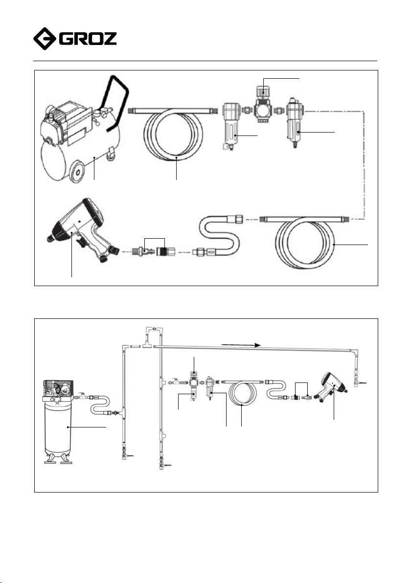
INSTALLATION
Air Pressure
Always use clean and dry air at 90 PSI
(6.2 bar) to operate the Pneumatic tools
Do not operate Pneumatic tools beyond the
maximum working air pressure of 90 PSI
(6.2 bar).
Air Line
For using pneumatic tools eciently, connect
air hose to the air inlet. Compressed air
has traces of moisture (water droplets)
in it and this moisture may permeate into
the pneumatic tools and cause mechanical
failure, therefore It is strongly recommended
to install an air filter, moisture separator,
regulator and lubricator in the air supply line.
Typical air supply setups are shown in the
following figures.