4
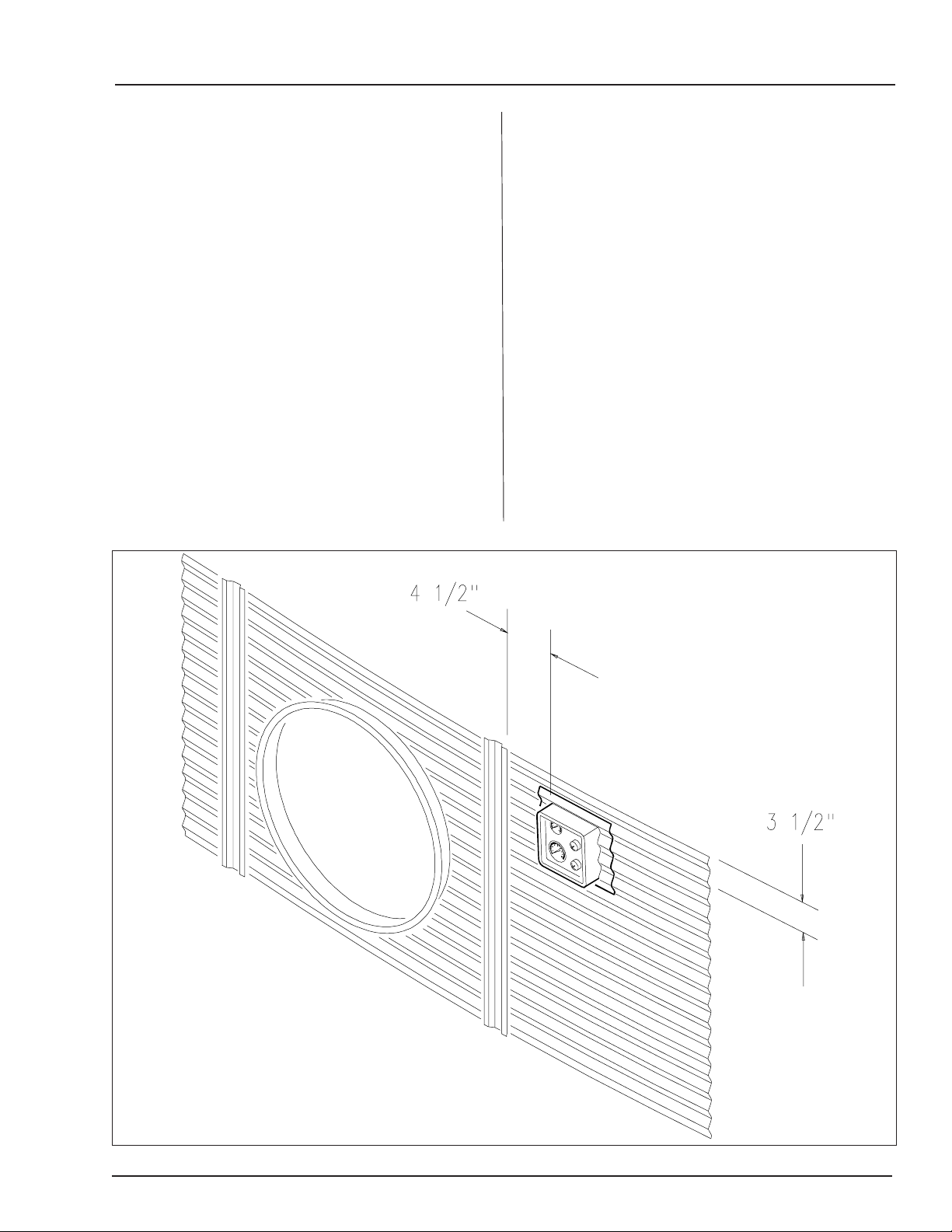
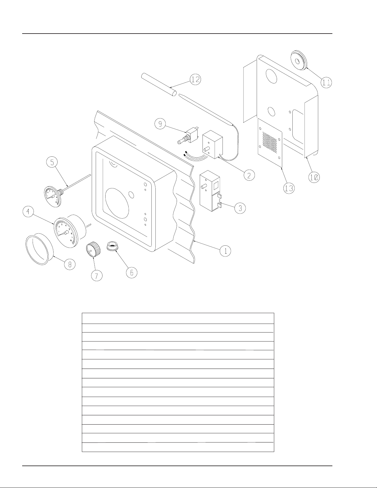
Humidistat-Thermostat
ROOF DAMAGE WARNING AND DISCLAIMER
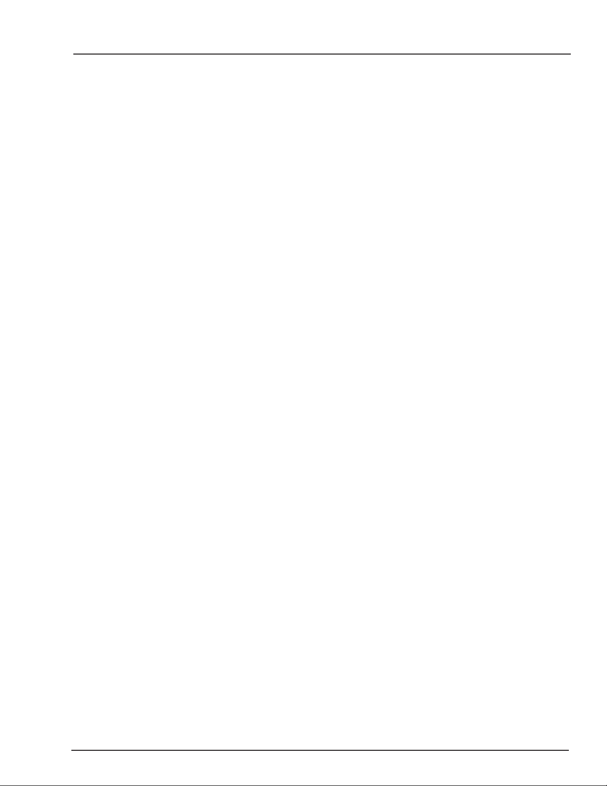
The symbol shown is used to call
your attention to instructions con-
cerning your personal safety.
Watch for this symbol; it points
out important safety precautions.
It means "ATTENTION",
"WARNING", "CAUTION", and
"DANGER". Read the message
and be cautious to the possibil-
ity of personal injury or death.
Safety Alert Symbol
GSI DOES NOT WARRANT ANY ROOF DAMAGE CAUSED
BY EXCESSIVE VACUUM OR INTERNAL PRESSURE FROM
FANS OR OTHER AIR MOVING SYSTEMS. ADEQUATE VEN-
TILATION AND/OR "MAKEUP AIR" DEVICES SHOULD BE
PROVIDED FOR ALL POWERED AIR HANDLING SYSTEMS.
GSI DOES NOT RECOMMEND THE USE OF DOWNWARD
FLOW SYSTEMS (SUCTION). SEVERE ROOF DAMAGE CAN
RESULT FROM ANY BLOCKAGE OF AIR PASSAGES. RUN-
NING FANS DURING HIGH HUMIDITY/COLD WEATHER
CONDITIONS CAN CAUSE AIR EXHAUST OR INTAKE
PORTS TO FREEZE.
ROOF WARNING, OPERATION & SAFETY
Thank you for choosing a GSI product. It is de-
signed to give excellent performance and service
for many years.
The principal concern of The GSI Group, Inc.
("GSI") is your safety and the safety of others asso-
ciated with grain handling equipment. This manual
is written to help you understand safe operating pro-
cedures, and some of the problems that may be en-
countered by the operator or other personnel.
As owner and/or operator, it is your responsi-
bility to know what requirements, hazards and
precautions exist, and to inform all personnel as-
sociated with the equipment, or who are in the
dryer area. Avoid any alterations to the equip-
ment. Such alterations may produce a very dan-
gerous situation, where serious injury or death
may occur.
Humidistat-Thermostat Operation
WARNING! BE ALERT!
Personnel operating or working around
electric fans should read this manual.
This manual must be delivered with the
equipment to its owner. Failure to read
this manual and its safety instructions is
a misuse of the equipment.